Project 2
1. Design a Warehouse Building located in Chennai using STAAD Pro Connect Edition. The specification must be as follows:
|
Width |
30m |
|
Length |
50m |
|
Eave Height |
9m |
|
Bay spacing |
6m |
|
Soil type |
Medium |
|
Safe Bearing Capacity |
200 kN/m2 |
|
Roof slope |
1 in 12 |
Assume suitable sections for structural elements. Follow IS800:2007, IS1893 and IS 875
- Prepare a Design Basis Report for the project
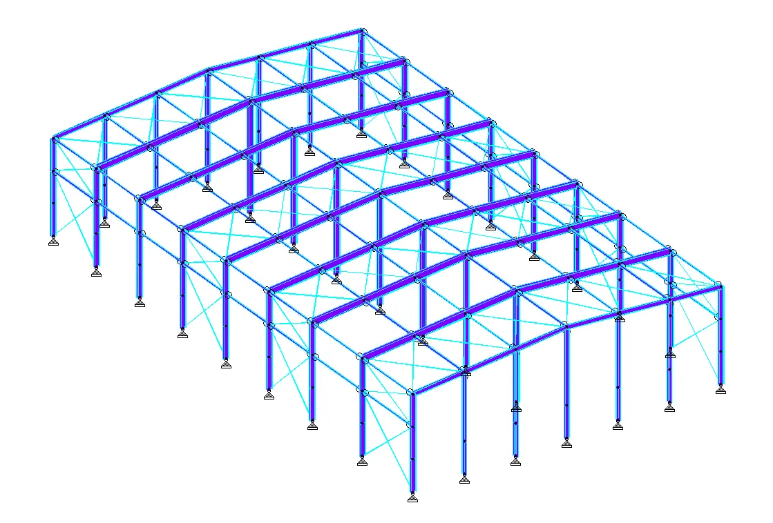
- Create structural model using STAAD Pro Connect Edition
- Prepare DL, LL, WL and EQL load calculations as per IS 875 standards
- Design using MS – Excel
- Steel column
- Rafter
- Base plate
- Pedestal
- Z- purlin
- Design Foundations using STAAD Foundation.
- Attach necessary sketches and drawings wherever required.
- All stipulations, assumptions and design parameter must adhere to Indian Standards.
AIM
Design a Warehouse Building located in Chennai using STAAD Pro Connect Edition
PROCEDURE
Open staad software an then create new page
then draw nodes and beams using giveen specification
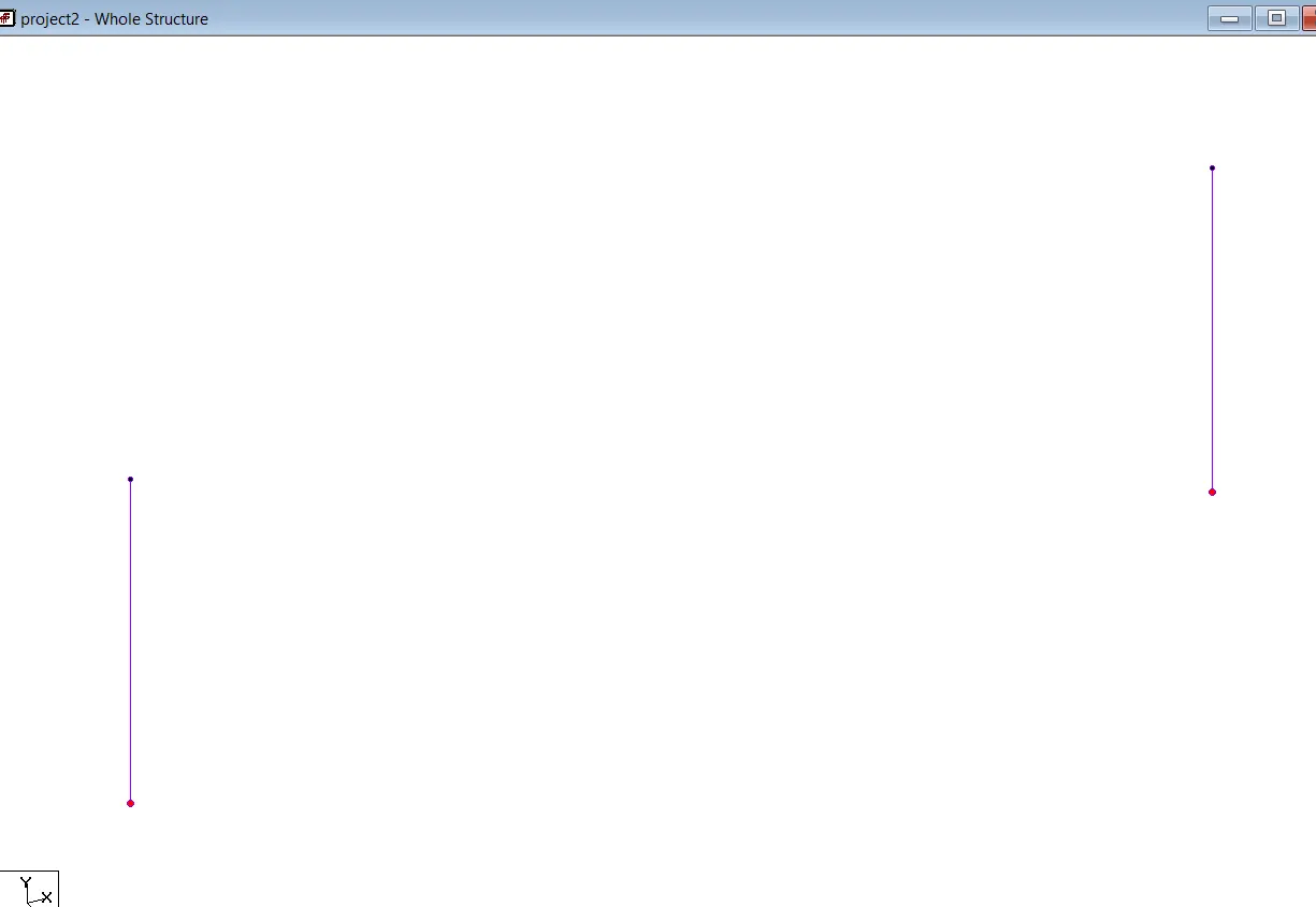
complete the skeltal structure using add beams nodes translational repeat
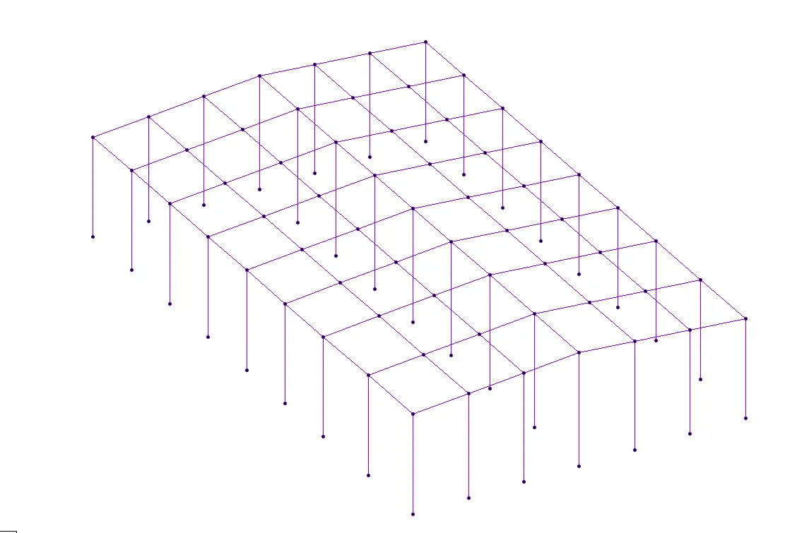
skeltal structure is formed
then add tie beams and brick wall nodes
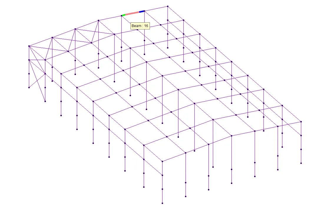
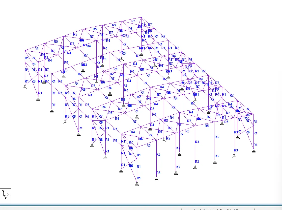
add bracings
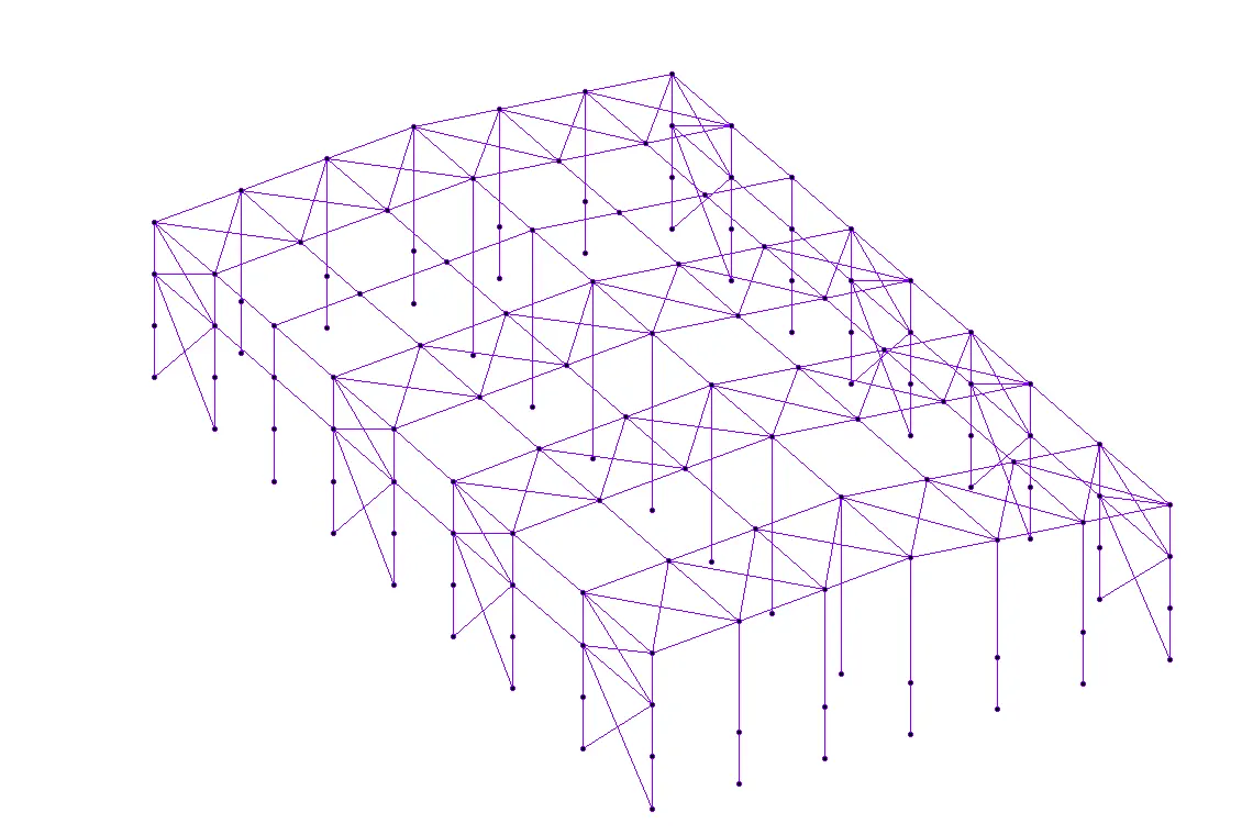
add support to the structure
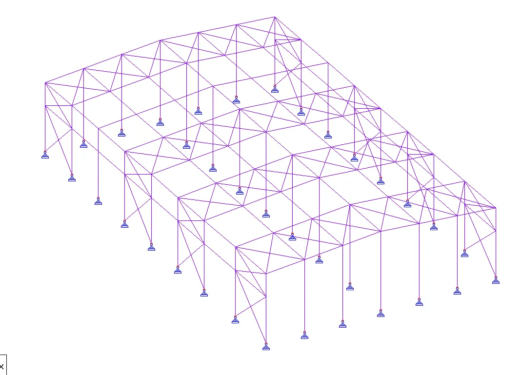
add properties
properties for end column
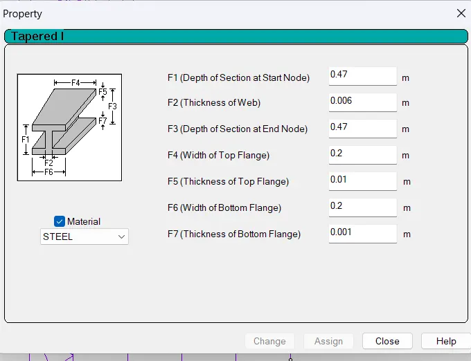
properties for middle column
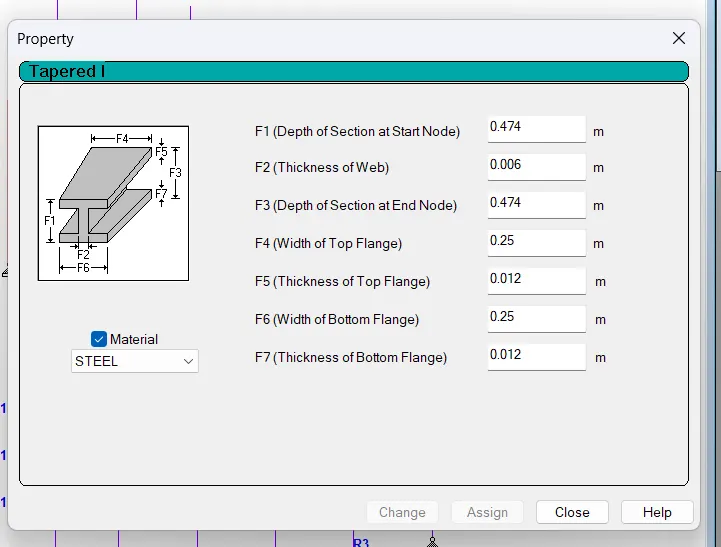
properties for gabble column
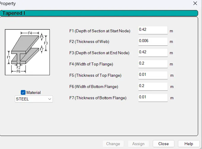
properties for main rafter
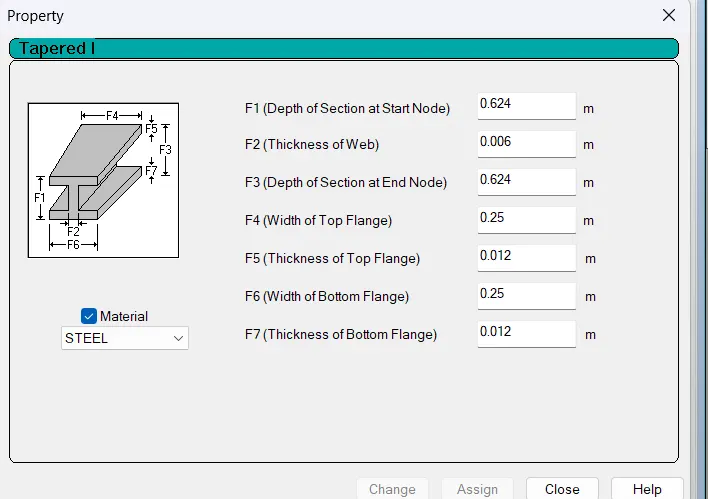
properties for gable rafter
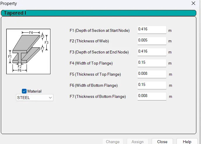
assign the properties
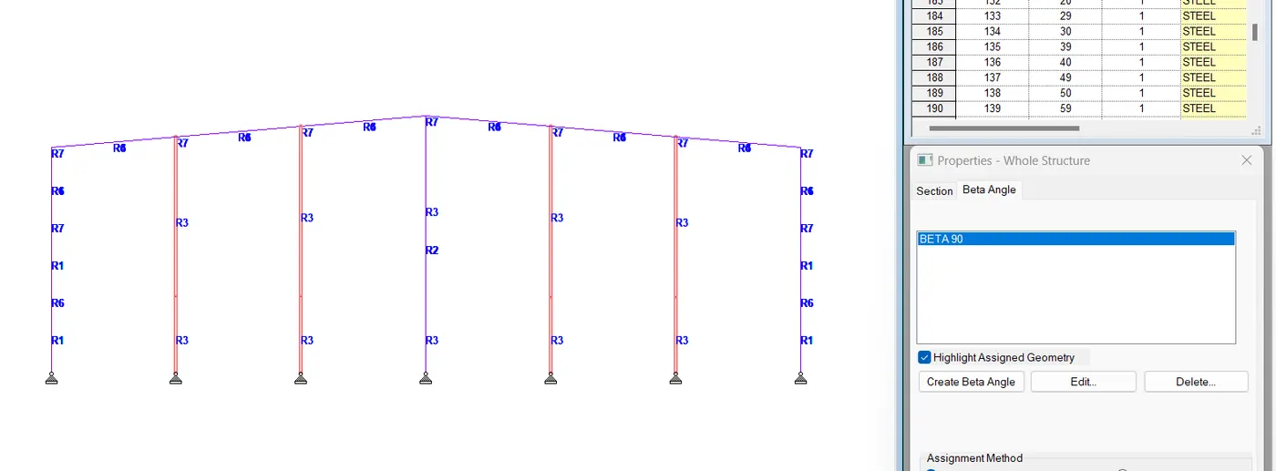
assign beta angle 90degree for gable columns
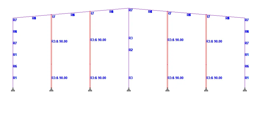
add materials steel
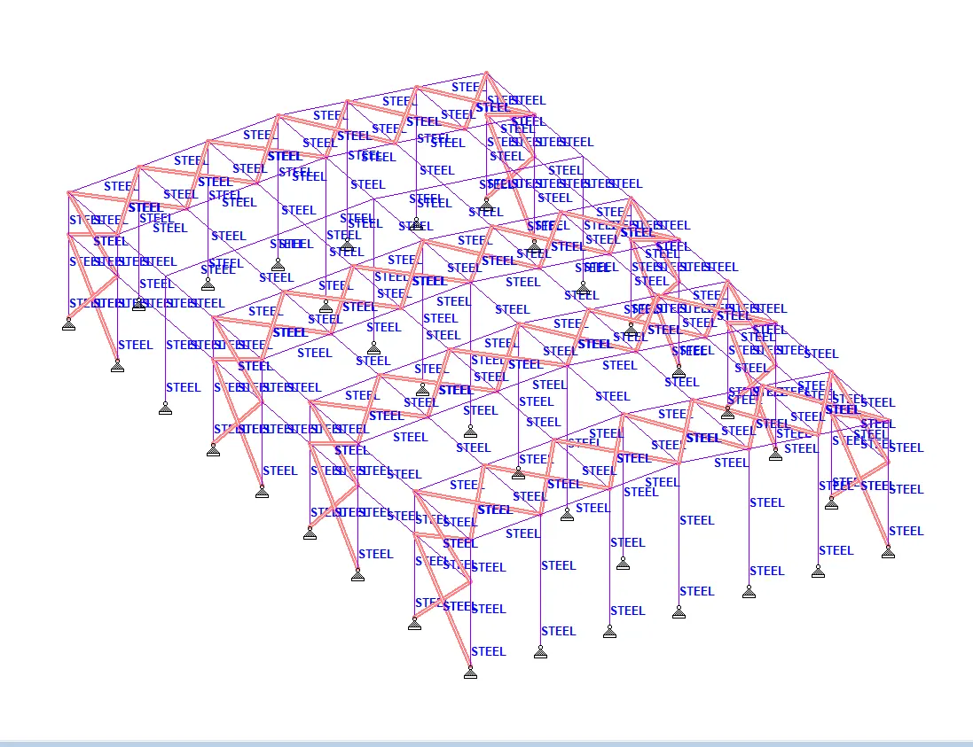
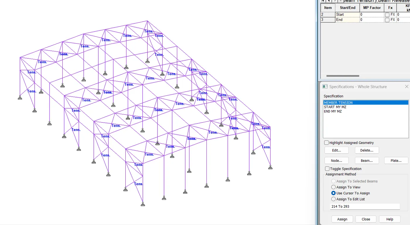
go to specification and assign as tension members
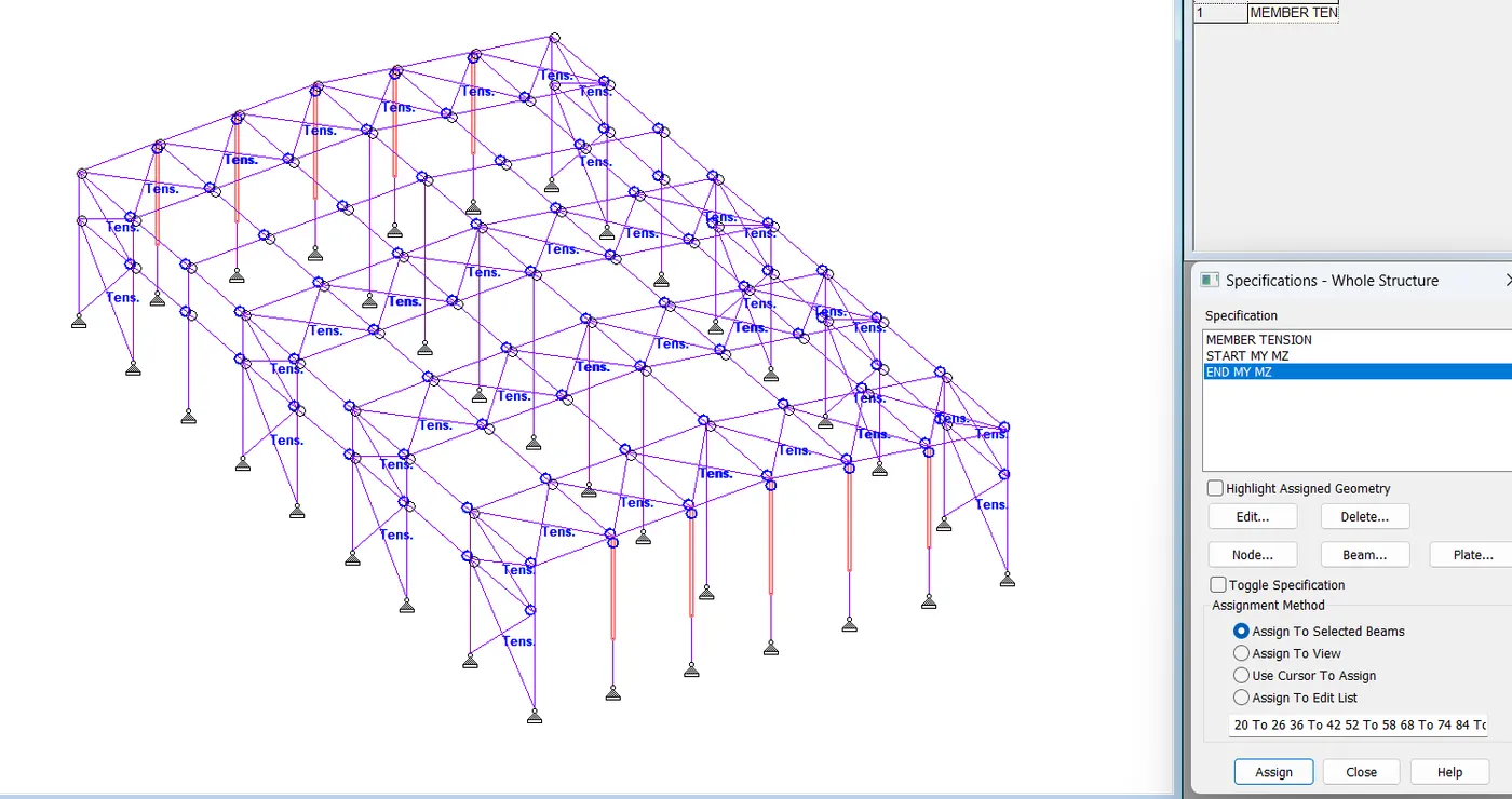
moment release at purlin members ( both start and end)and geble members unsupport ends
now add and assign the loads
first go to loads and add load cases
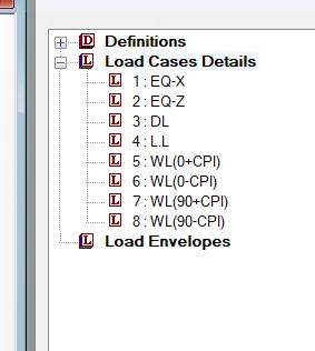
LOAD CALCULATIONS
DEAD LOAD
SELF WEIGHT = -1.15
DL ON RAFTER = WEIGHT OF ROOF SHEETING+WIGHT OF SAG ROD & BRACES+COLLATERAL LOAD
= 5+5+10 = 20kg/m^2
= 0.2kn/m^2
UDL on rafter = 0.2*6 =1.2 KN/M
UDL ON RAFTER FROM PURLIN =8*6*8.77/15
= 28.06Kg/m=0.28N/m
UDL ON MAIN FRAME = 1.2+0.28= 1.48KN/M
UDL ON GABLE FRAME = 0.74KN/M
DEAD LOAD ON COLUMN
LOAD FROM SAG ROAD AND BRACES = 0.1*6=0.6KN/M
LOAD DUE TO GRIT = 8.77*6*6/6 =52.62KG/M
= 0.52KN/M
TOTAL = 0.6+0.52
TOTAL LOAD ON COLUMN =1.12KN/M
LOAD ON GABLE COLUMN = 0.56 KN/M
LOAD ON WIND COLUMN
LOAD FROM SHEET AND SAG ROADS = 0.1*6=0.6KN/M
LOAD DUE TO WEIGHT OF GIRTS = 6.32*6*6/6
= 37.92Kg/M
= 0.37KN/M
TOTAL LOAD = 0.6+0.37 =0.97KN/M
DEAD LOAD EAVE STRUT & GUTTER =1.16KN(FOR MAIN)
=0.58 KN (FOR GABLE)
LIVE LOAD CALCULATION
L.L ON ROOF = 0.75 KN/M^2
UDL ON MAIN FRAME RAFTER = 0.75* 7=5.25KN/M
UDL ON GABLE FRAME= 0.5*5.25 = 2.625KN/M
LOAD DUE TO WEIGHT OF WATER IN GUTTER
MAIN FRAME = 0.25 *0.25*10*6 = 3.75KN
Gable frame = 0.5*4.375=2.187KN
ADD AND ASSIGN DEAD LOAD AND LIVE LOAD TO THE STRUCTURE
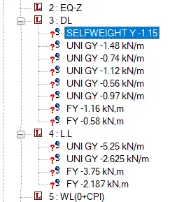
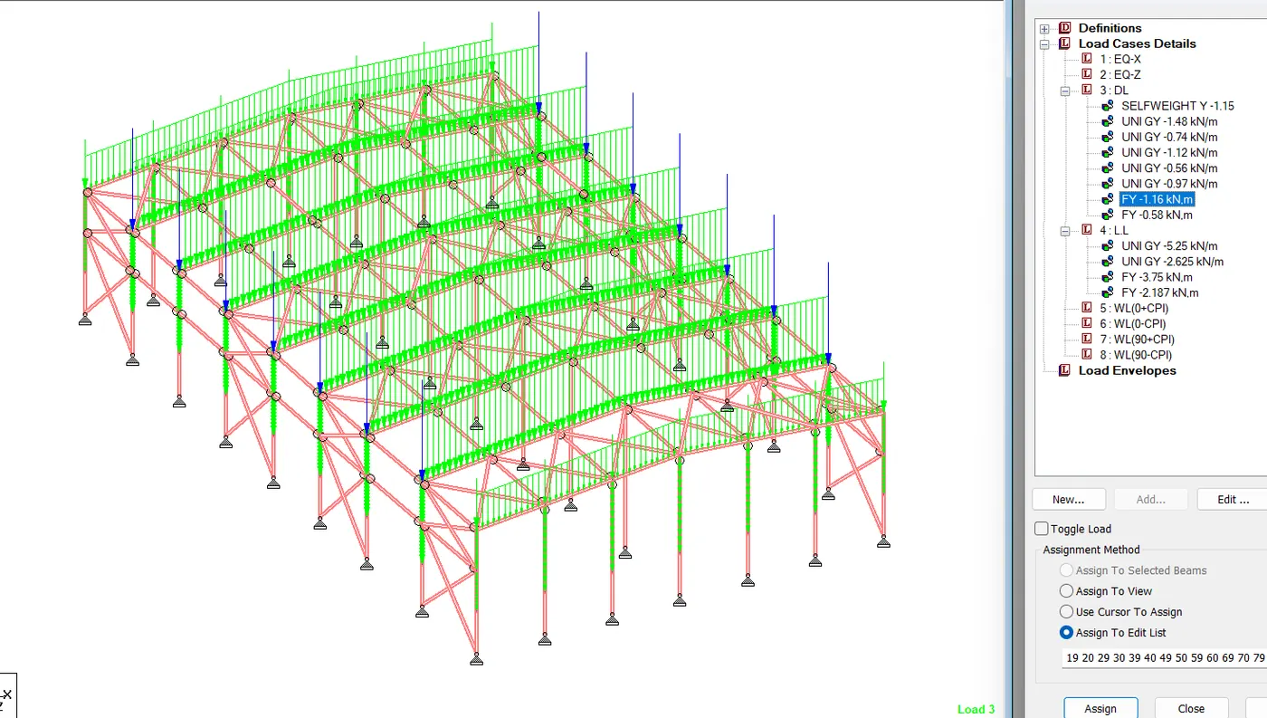
Add earthquake load before add earth quake load add definition
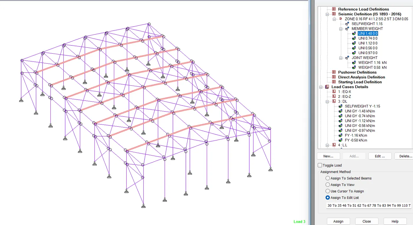
after add and assign seismic definition add earthquake load
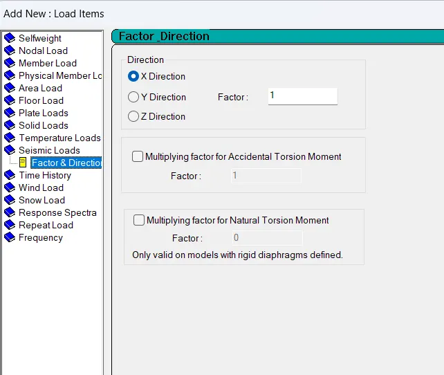
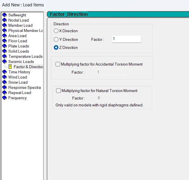
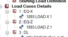
FOR WIND LOAD CALCULATION
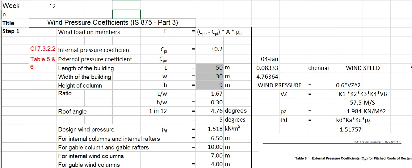
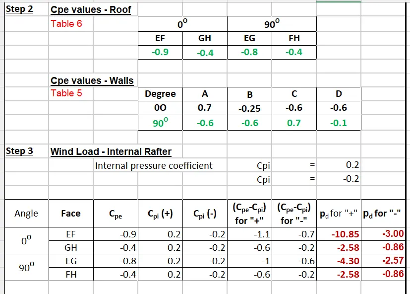
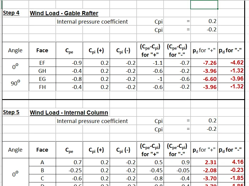
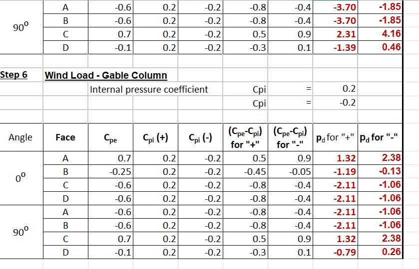
add the wind load
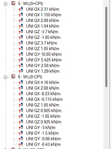
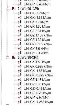
then assign the loads
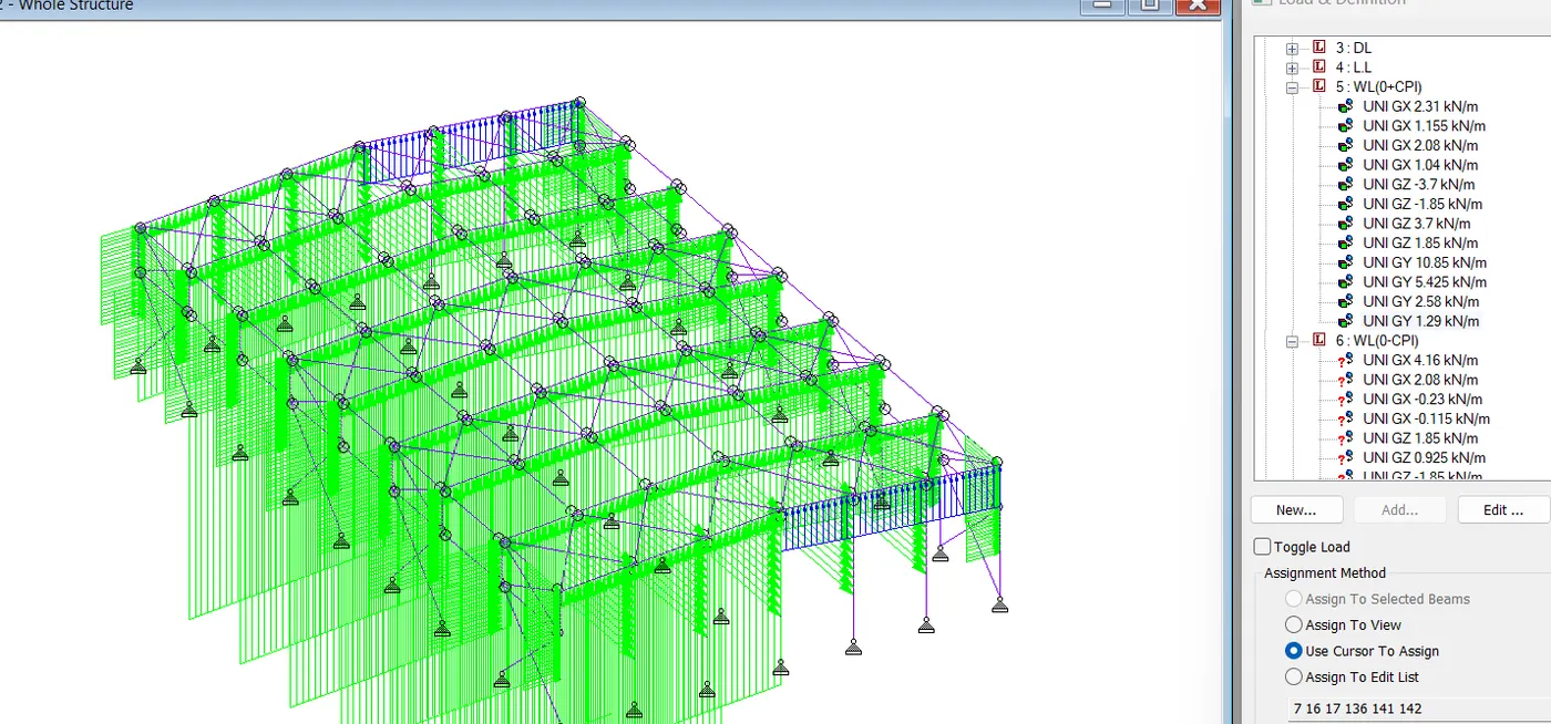
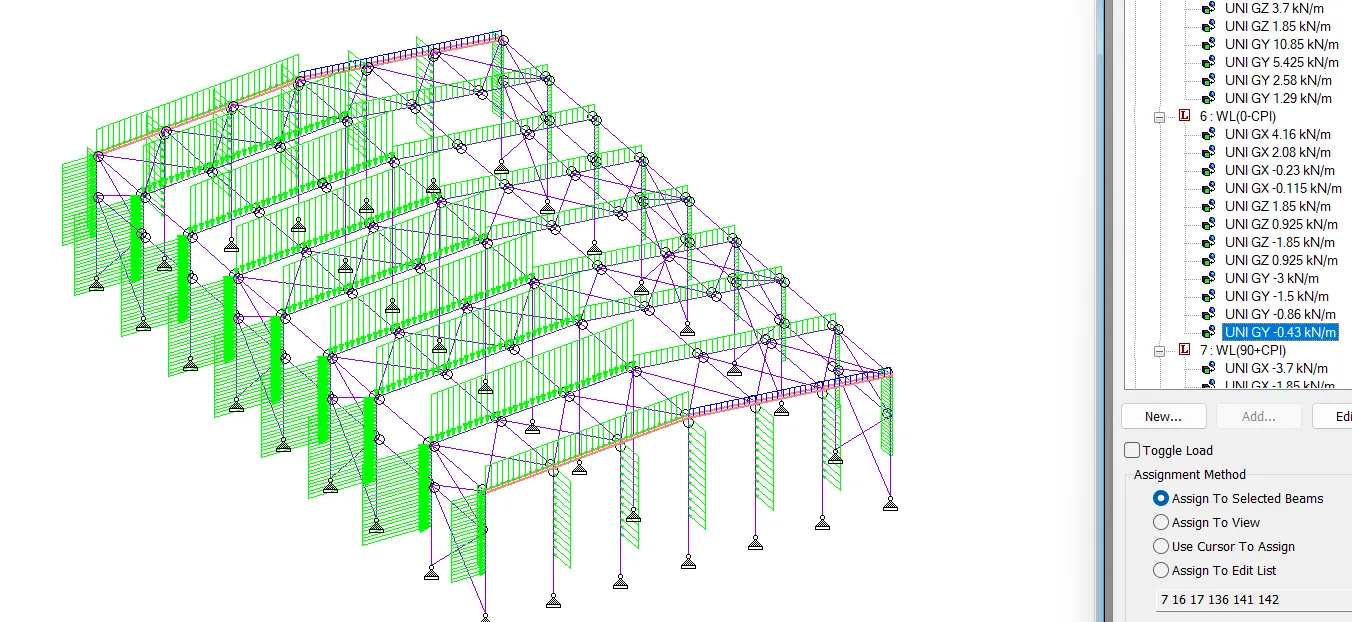
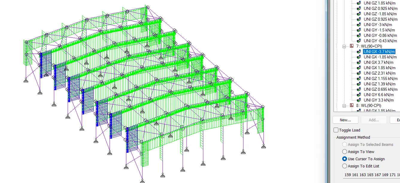
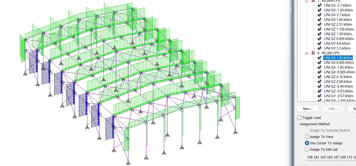
Then design the structure for that go to design and select is code for design
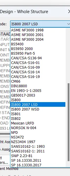
FOR BRACINGS
fu=420000KN/M^2
FY=250000KN/M^2
MAIN FRAME ,GABLE FRAME ,COLUMN AND RAFTER
FU= 490000KN/M^2
FYLD = 345000KN/M^2
PURLINS
FU=450000KN/M^2
FYLD=310000KN/M^2
Add and assign the values
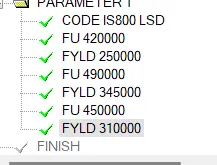
now assign all the parameters
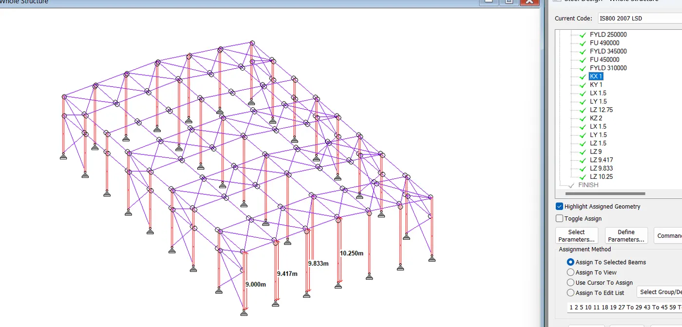
add and assign main 180 ratio=1
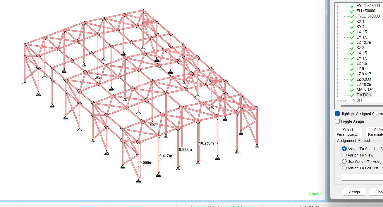
then add command and assign take off
then add and assign command check code
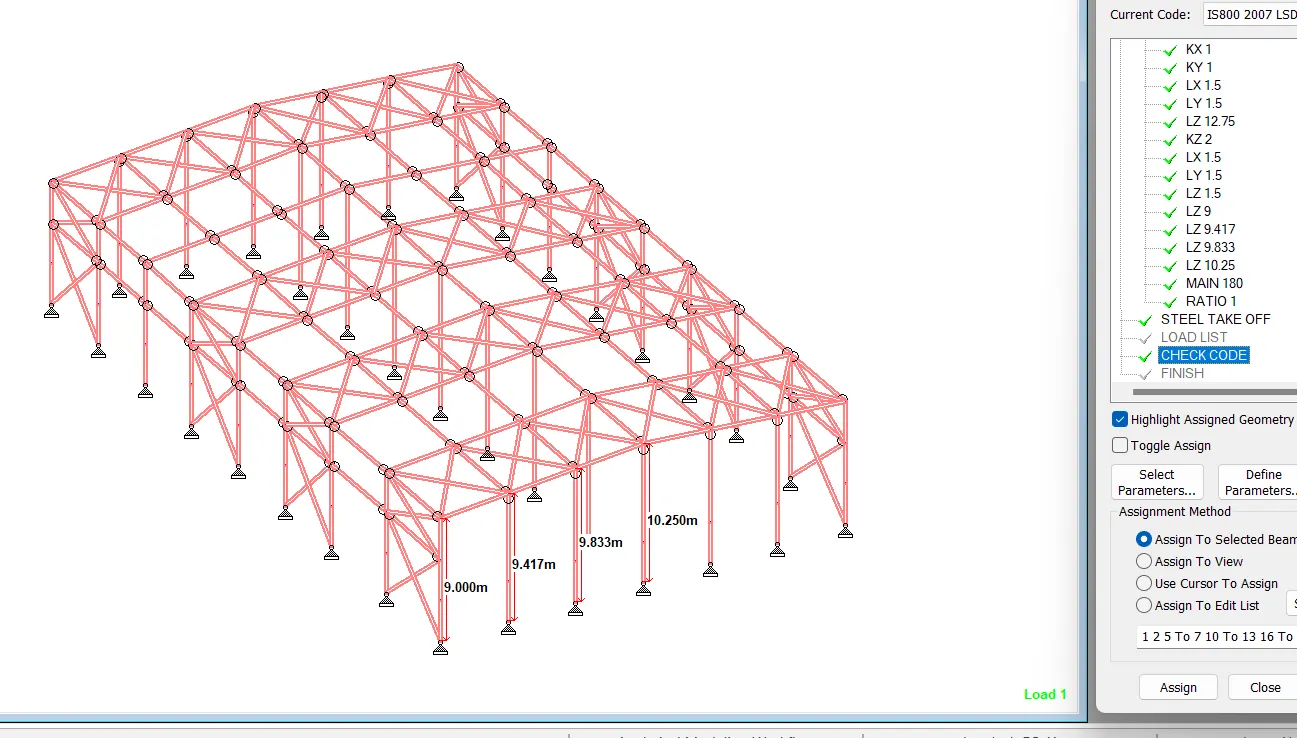
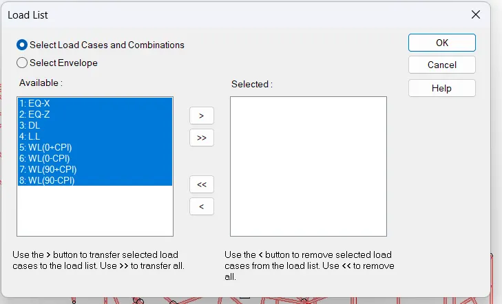
then go to analysis and load list add
then add analysis type as perform analysis
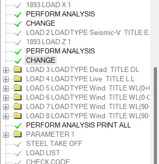
then rue the analysis
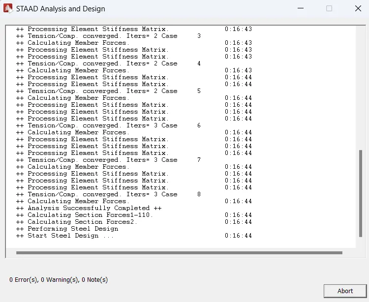
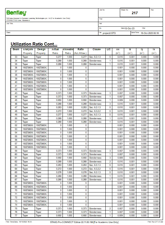
for Design basic report go to report setup reports
add input and out puts
- Prepare a Design Basis Report for the project


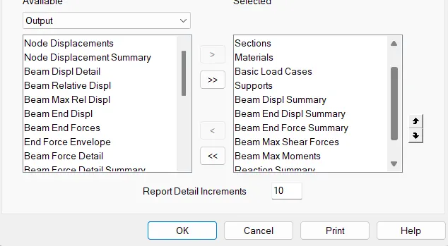
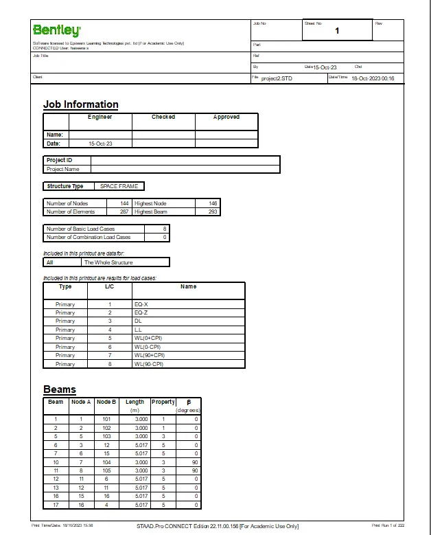
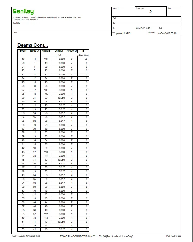
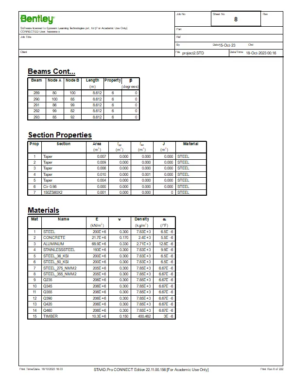
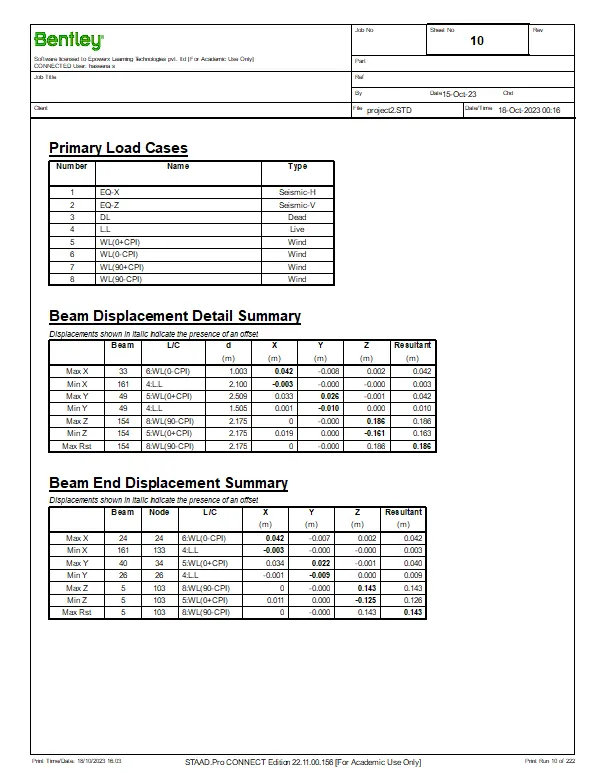
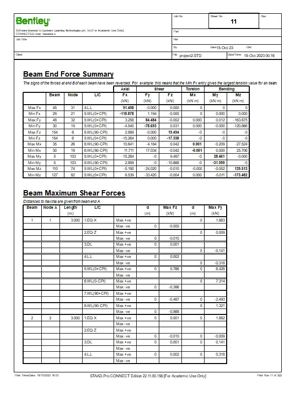
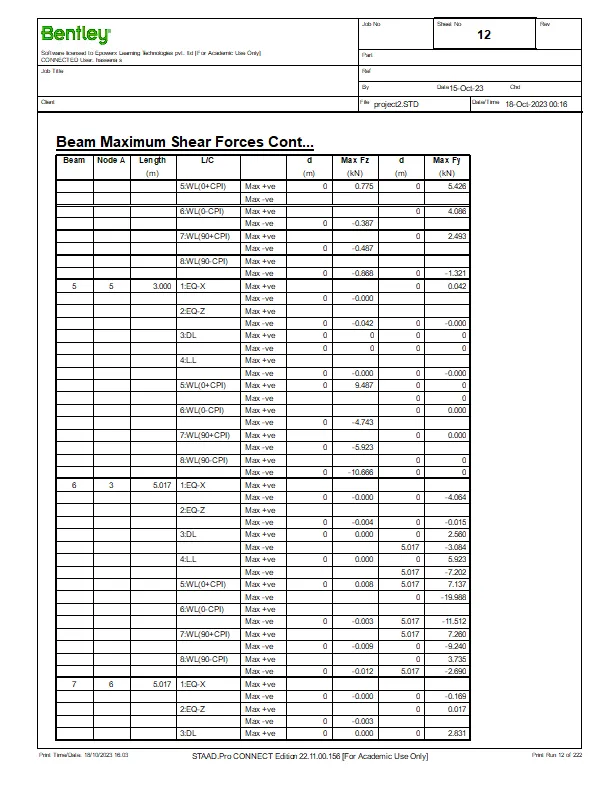
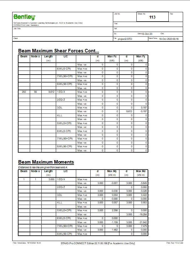
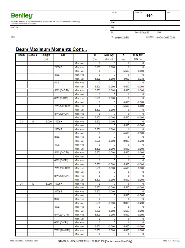
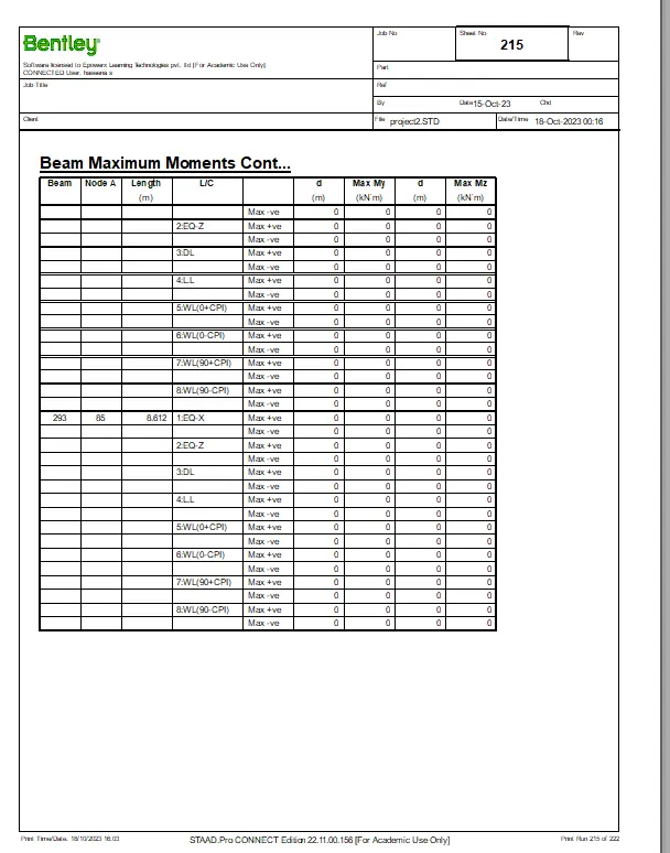
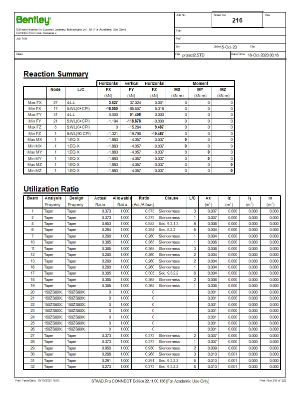
- Create structural model using STAAD Pro Connect Edition
1.2Design using MS – Excel
- Steel column
- Rafter
- Base plate
- Pedestal
- Z- purlin
a) Steel column :-
Height of column h = 9m
Yeild strength fy = 250N/mm^2
Elastic modulus E = 200000N/mm^2
Material factor γm = 1.1
Step :- 1
Section classification
Properties of selected section
| ISHB | 400 |
| A | 10466mm^2 |
| h | 400mm |
| B | 250mm |
| t | 10.6mm |
| T | 12.7mm |
| rx | 166.1mm |
| ry | 51.6mm |
| Zp | cm^3 |
Flange criterion b/T = 9.84
Web criterion d/t = 35.34
ε = 1
b/T < 10>
d/t < 42>
The section is classified as COMPACT
Step :- 2
Effective length
As both ends pin-jointed
KLx = 9m
KLy = 9m
KLz = 9m
Slenderness ratio
KLx/rx = 54.18
KLy/ry = 174.42
Non-dimensional effective slenderness ratio
λ = 1.964
Step :- 3
To calculate φ
h/bf = 1.60
> 1.2
T = 12.7mm
So, buckling class = b
α = 0.34
φ = 0.5(1+α(λ-0.2)+λ^2)
φ = 2.73
Step :- 4
Claculation of χ
χ = 0.216N/mm^2
Step :- 5
Calculation of fcd
fcd = χfy/γm
= 49.17
Step :- 6
Factored Axial Load
Pd = Afcd
= 514.614kN
b) Rafter :-
Span of I beam = 6m
Dead load = 18kN/m
Imposed load = 40kN/m
Length of bearing = 100mm
Yield strength = 250N/mm^2
Step :- 1
Design load calculation
Factored load = 87kN/m
Factored bending moment = 391.5kNm
Step :- 2
Section modulus required
Zreqd = 1722600mm^3
= 1722.60cm^3
Step :- 3
Section classification
c) Base plate :-
d) Pedestal :-
Grade of concrete = 40N/mm^2
Load = 123kN
Moment = 116kNm
Horizontal shear = 13kN
Yield strength = 250N/mm^2
Length of base plate L = 450mm
Width of the base plate B = 350mm
C/C distance of (Ld) of bolt group in Z = 300mm
C/C distance of (Ld) of bolt group in X = 180mm
Bearing strength of concrete fc = 16N/mm^2
Depth of column D = 300mm
Width of column W = 250mm
Step :- 1
Anchor Bolt Details
Dia of anchor bolt = 24mm
No of anchor bolt on each side = 4
Total number of anchor bolt,n = 8
Gross area of the bolt 'Asb' = 452.16mm^2
Net area of the bolt 'Anb' = 352mm^2
Ultimate tensile strength of the bolt fub = 400N/mm^2
Fyb(Anchor bolt) = 240N/mm^2
Step :- 2
Base plate details
Ultimate tensile strength of a plate,fu = 490N/mm^2
Thickness of plate = 16mm
Yield stress of plate = 330N/mm^2
Step :- 3
Anchor bolt design
Area of the plate = 157500mm^2
Stress Max pressure σ1 = F/A+6*Mz/BL^2
= 10.60N/mm^2
< 16>
OK
Min pressure σ2 = F/A-6*Mz/BL^2
= -9.04N/mm^2
< 16>
C = L*σ1/(σ1+σ2)
= 242.89mm
a = L/2-C/3
= 144.04mm
e = (L-Ld)/2
= 75mm
y = (L-C/3-e)
= 294.04mm
Tension in anchor bolts along the length of plate
FT = (Mz-Fxa)/y
= 364.38
Tension per bolt = 91.10kN
shear per bolt,V = 1.63kN
Step :- 4
Shear check
Factored shear force Vsb = 1.63kN
Vd,sd = 81290.9N
= 21.291kN
Factored Vd,sb = 65.03kN
Step :- 5
Tensile check
Factored tensile force in bolt Tb = 91.10kN
Tensile strength of bolt Td,b = Tnb/γmb
Tn,b = 0.9fubAn
= 126720N
= 126.72kN
Tn,b = fybAsb(γmb/γmo)
= 123316N
= 123.316kN
Lesser of two =123.32kN
So, Td,b = 98.65kN
Step :- 6
Combined unity check
(Vsb/Vdb)^2+(Tb/Tdb)^2
Vsb/Vdb = 0.025
Tb/Tdb = 0.92
Unity check = 0.85
< 1>
Hence OK
Step :- 7
Anchor bolt length
Bond strength in tension bd = 1.4N/mm^2
Anchor length required = Tb/(3.14*d*τbd)
= 863.44mm
Let anchor bolt bolt length = 900mm
e) Purlin :-
Step :- 1
Span of the purlin = 7m
Spacing of the purlin = 1.5m
Number of sag rods = 1
Slope of the roof = 5deg
Step :- 2
Dead loads
Weight of sheeting = 5kg/m^2
Self weight of purlin = 4.22kg/m^2
Additional load = 10%
= 0.42kg/m^2
Total dead load = 0.096kN/m^2
Live loads
Live load on roof = 75kg/m^2
= 0.75kN/m^2
Wind loads
Basic wind spped = 50m/s
Terrain category = 2
Building class = B
k1 = 1
k2 = 1
k3 = 1
Design wind speed Vz = 57m/s
Design wind pressure Pz = 1949.40N/m^2
= 1.95kN/m^2
Length of the building I = 50m
Breath of the building w = 30m
Height of the building h = 10.5m
Height of the building at eaves = 9m
h/w = 0.35
I/w = 1.67
External pressure coefficient
Maximum downward Cpe = -0.4
Maximum upward Cpe = -0.7
Internal pressure coefficient
Maximum positive Cpi = 0.5
Maximum negative Cpi = -0.5
For maximum upward wind force
Maximum upward Cpe = -0.7
Cpi = -0.5
Cpe + Cpi = -1.2
Pz = 1.95
Wind pressure for purlin design = -2.339kN/m^2
For maximum upward wind force
Max upward Cpe = -0.4
Cpi = 0.5
Cpe + Cpi = 0.1
Pz = 1.95
Wind pressure for purlin design = 0.195kN/m^2
Step :- 3
Design load calculation
Spacing of purlin = 1.5m
Slope of roof = 5deg
Total dead load = 0.096kN/m^2
DL normal component = 0.144kN/m
DL tangential component = 0.013kN/m
Total live load = 0.75kN/m^2
LL normal component = 1.121kN/m
LL tangential component = 0.098kN/m
WL1 wind load = -2.339kN/m^2
WL normal component = -3.496kN/m
WL2 wind load = 0.195kN/m^2
WL normal component = 0.291kN/m
Summary of loads
| DL+LL | DL+WL1 | DL+LL+WL2 | |
| Normal load | 1.265 | -3.351 | 1.556 |
| Tangential load | 0.111 | 0.013 | 0.111 |
| DL+LL | 0.75(DL+WL1) | 0.75(DL+LL+WL2) | |
| Normal load | 1.265 | -2.514 | 1.167 |
| Tangential load | 0.111 | 0.009 | 0.083 |
Maximum normal component = 1.265kN/m
Step :- 4
Purlin section
Section selected = Zx200x6x2.3
Yield stress of material = 2400kg/cm^2
Flange width b = 60mm
Depth of section d = 200mm
Thickness t = 2.30mm
Length of Lip lip_I = 20mm
Internal bending radius = 3mm
Area = 8.07cm^2
Zxx = 47.72cm^3
Zyy = 10.22cm^3
Ixx = 477.18cm^4
Iyy = 61.34cm^4
Weight of purlin = 6.335kg/m
=4.223kg/m^2
Check for basic properties
t = 2.30mm
w = 49.40mm
Fy = 2400kg/cm^2
w/t = 21.48
< 60>
OK
Check for stress
Span major axis = 7m
Span minor axis = 2m
BM coefficient for Mxx = 10
BM coefficient for Myy = 10
| DL+LL | DL+WL1 | DL+LL+WL2 | |
| Normal load | 6.198 | 16.422 | 7.625 |
| Tangential load | 0.060 | 0.007 | 0.060 |
| Mxx/Zxx | 129.878 | 344.133 | 159.789 |
| Myy/Zyy | 5.895 | 0.672 | 5.895 |
| (Mxx/Zxx)+(Myy/Zyy) | 135.773 | 344.805 | 165.684 |
Maximum compressive stress = 344.80N/mm^2
1435/sq.root of f = 24.44
> 21.48
Hence section OK
Step :- 5
Combined Bending And Shear stresses in web
h/t = 84.96
| DL+LL | DL+WL1 | DL+LL+WL2 | |
| Fbw | 506.539 | 673.697 | 637.697 |
| Fv | 735.223 | 977.847 | 977.847 |
Actual stress
| fbw | 129.878 | 344.133 | 159.789 |
| fv | 5.895 | 0.672 | 5.895 |
| fbw/Fbw | 0.256 | 0.511 | 0.237 |
| fv/Fv | 0.008 | 0.001 | 0.006 |
| Sqrt of sum of squares | 0.257 | 0.511 | 0.237 |
Maximum combined stresses = 0.511
< 1>
OK
Step :- 6
Check for deflection
Number of spans = 3
Deflection = (3/384)(wl^4/EI)
w = 3.351kN/m
Span = 6m
E = 207400N/mm^2
Ixx = 477.18cm^4
δ = 34.29mm
Allowable deflection δ = Span/180
= 33.33mm
> 34.29
Not OK
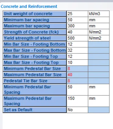
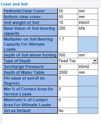
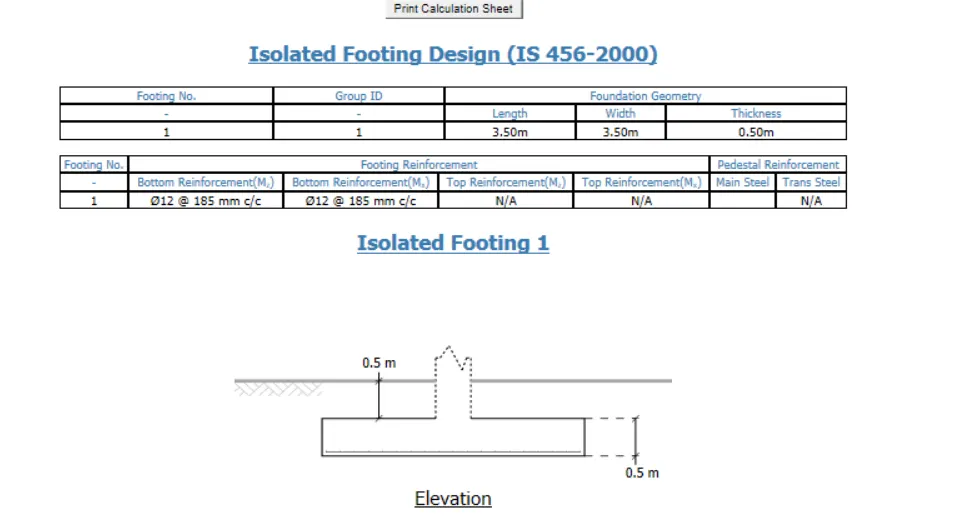
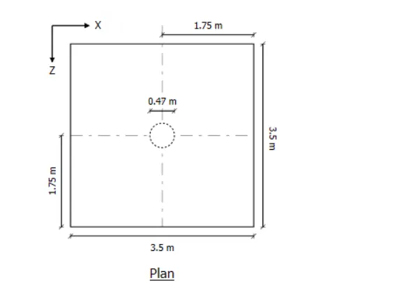
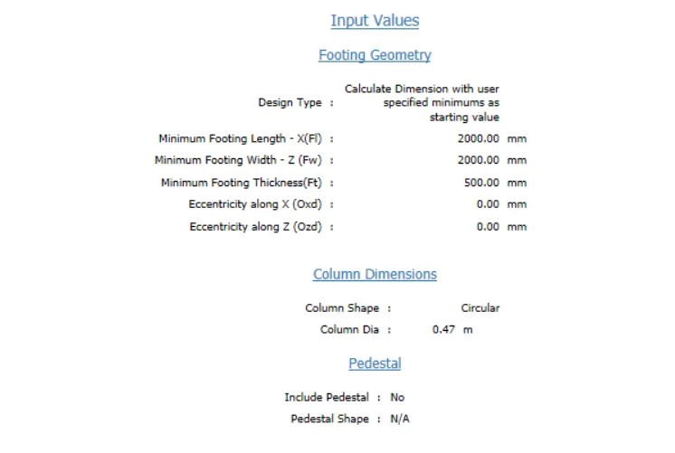
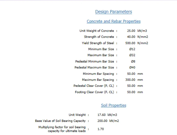
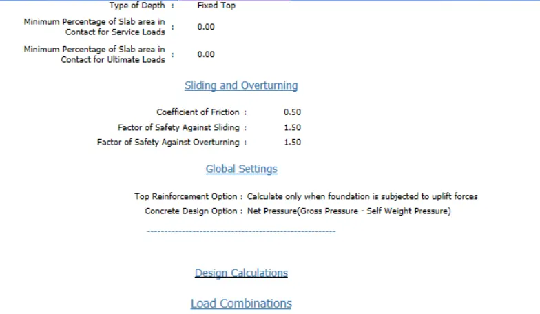
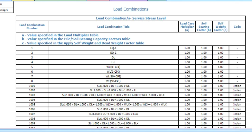
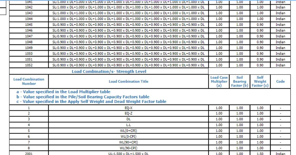
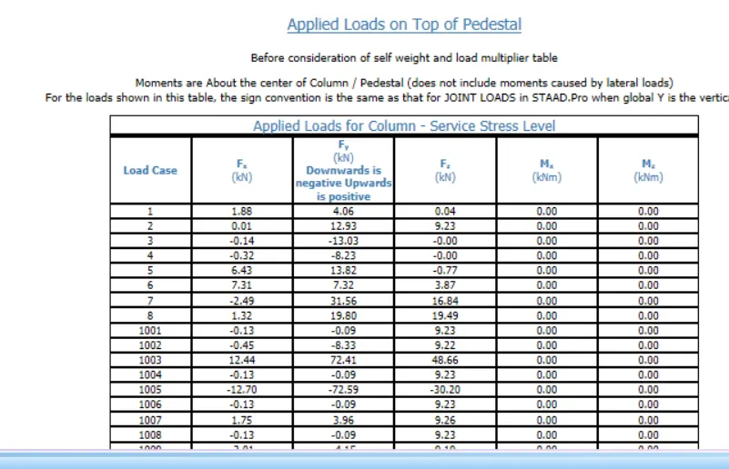
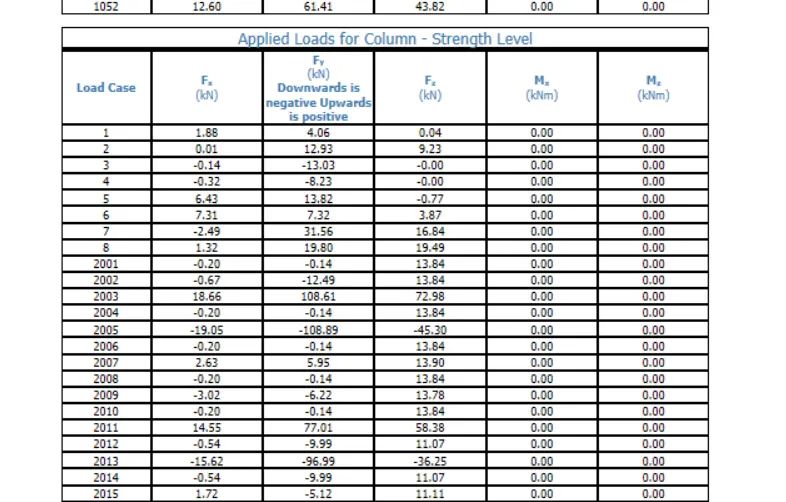
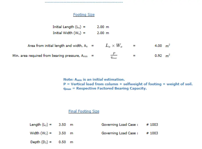
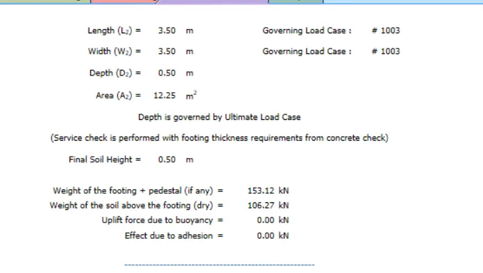
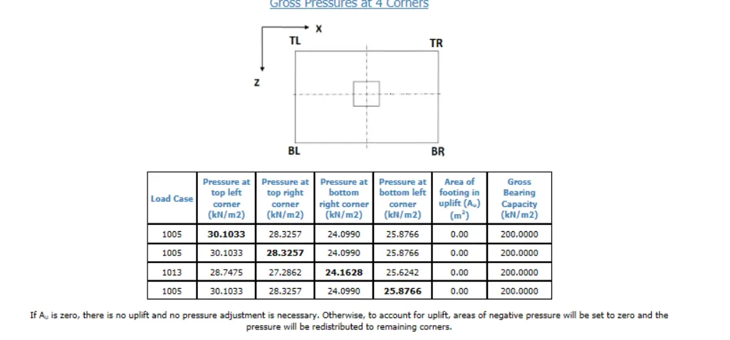
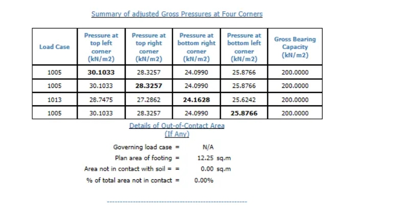
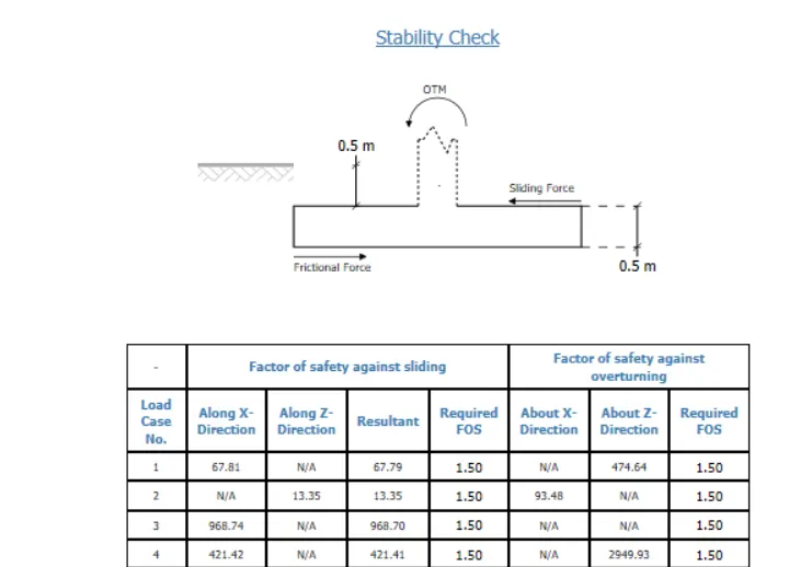
- Design Foundations using STAAD Foundation.
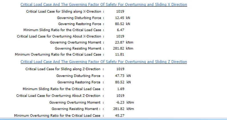
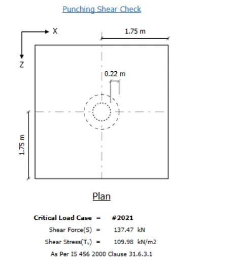
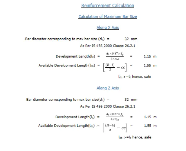
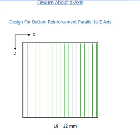
for the design of foundation go to staad foundation
included all the loads
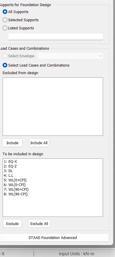
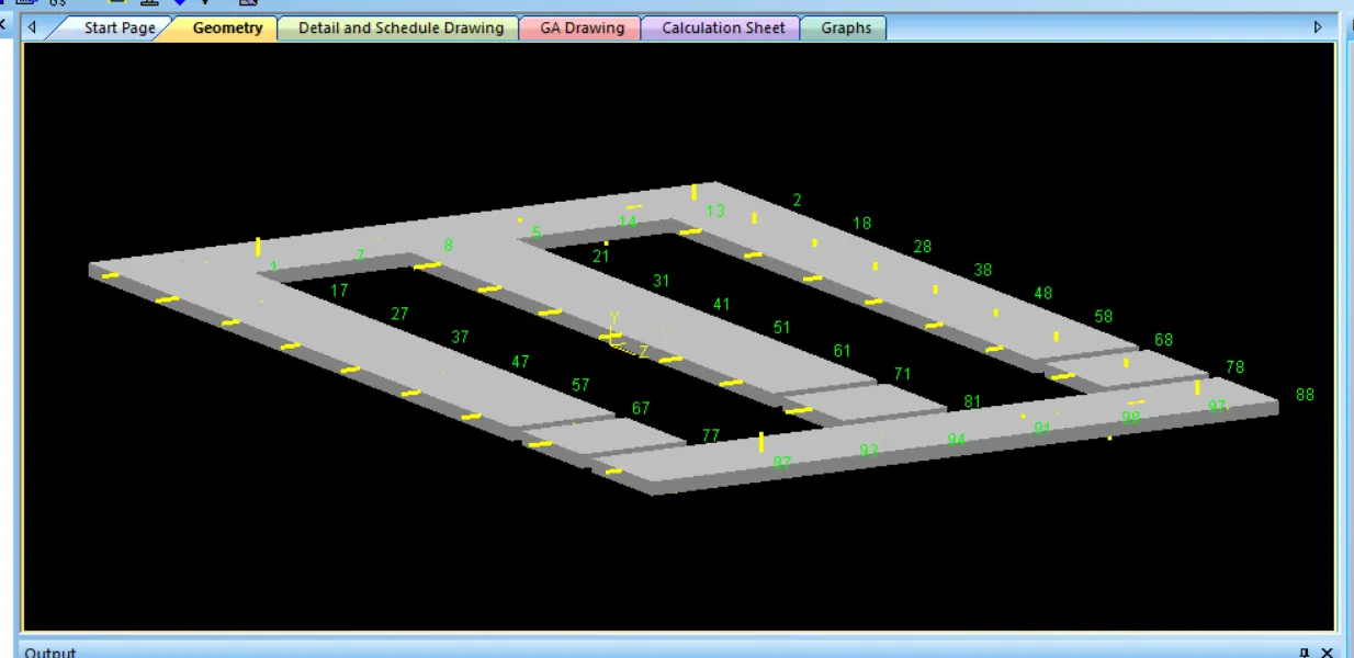
given job name and given job name as isolated footing
then go to job set up and add design parameters
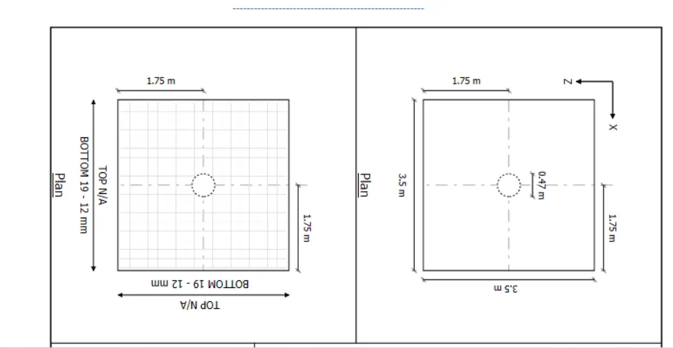
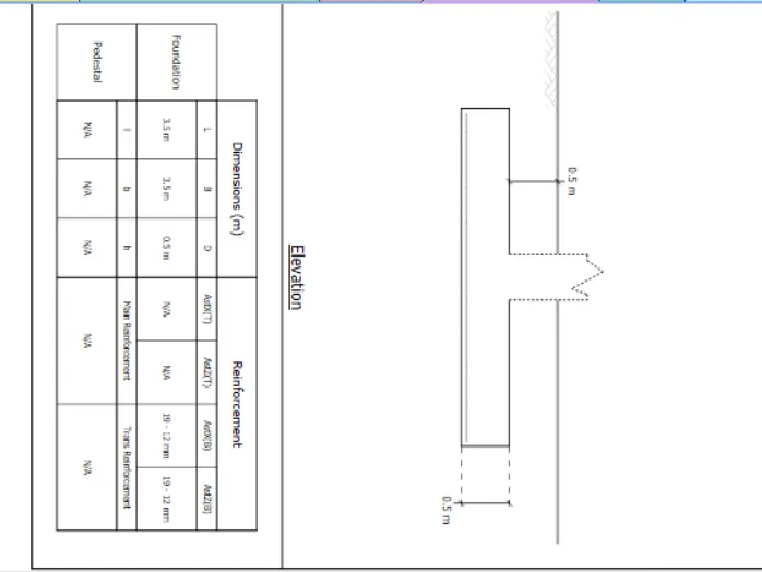
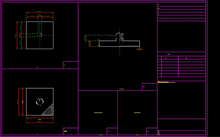
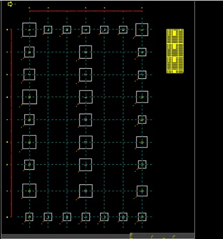
RESULT
USING STAAD WAREHOUSE IS DESIGNED
FOUNDATION DETAILS
2. Design a simply supported gantry girder to carry electric overhead travelling crane
Given:
Span of gantry girder = 7 m
Span of crane girder = 9 m
Crane capacity = 250 kN
Self-weight of trolley, hook, electric motor etc. = 40 kN
Self-weight of crane girder excluding trolley = 100 kN
Minimum hook approach = 1.0 m
Distance between wheels = 3 m
Self-weight of rails = 0.2 kN/m