Project 2
AIM:
To route the wiring harness bundle for the given body.
Objective:
The main objective of this project is:
- To create the wiring harness routing for the given Car body by using appropriate connectors, clips and clamps which is required.
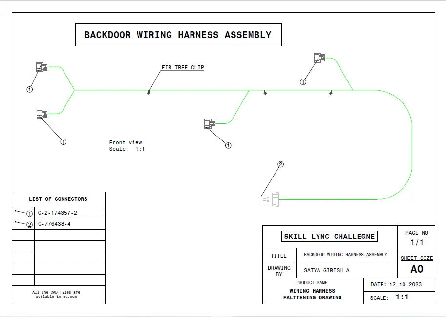
- To create a flatten view drawing file in Catia v5.
- Need to apply the protection covering like cot tubes and insulation tapes to the bundles as required.
- Need to apply the industry best packaging rules and best practices studied in this course.
Packaging rules and assumptions made in this project:
- Avoid harness routing and clipping in a blind zone.
- Avoid harness routing through the small structural holes and openings to minimise the chaffing and handling of the wiring harness during installation.
- Provide additional slack to the harness according to the surrounding and harness bending requirements. And avoid excess slack to the harness.
- Provide sufficient clearance to the different surrounding parts.
- Avoid routing over the bolts, near to the bolted joints or screwed joints. Because it may damage the harness or may puncture the harness.
- Avoid routing near the sharp edges like thin sheet metal brackets, panel joints, etc.
- Provide at least 100mm clearance to the harness from the ABC pedals, clutch lever & cables, Engine timing belt or any other dynamic components.
- Enough clips and clamps should be provided to ensure the positive clearance with the surrounding and safety of the wiring harness.
- Ensure distance between two clamps on a straight branch should be maximum of 200mm.
- Clamping requirements should be decided based on the harness bending, surrounding and mounting arrangements.
- Provide positive clamping at the engine and chassis to avoid the harness damage when Engine rocks.
- Keep harness away from the transmission dynamic assemblies like drive shaft or propeller shaft.
- Provide the guiding channel if it is required.
- Use the rubber gromets which provide the proper sealing, and also protects the harness from the sharp edges and absorbs the vibrations.
- Wiring harness minimum branch length should be 50mm.
- Minimum distance between the clip and nearest branching point should be atleast 25mm.
- Minimum distance between two breakouts should be 50mm.
- Limit the number of branches coming out from the single branch to 4.
- Provide the bracket for the interconnection connector parking.
Steps followed for creating the wiring harness routing to the given V-16 Engine:
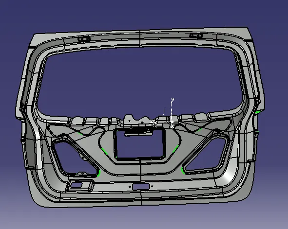
STEP 1: Download the cad files of the given car body, connectors, clips and clamps.
CAR BODY (TAIL GATE DOOR):
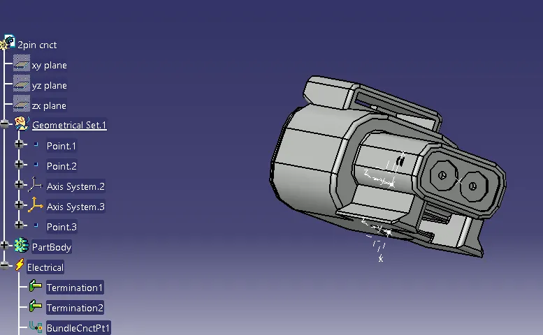
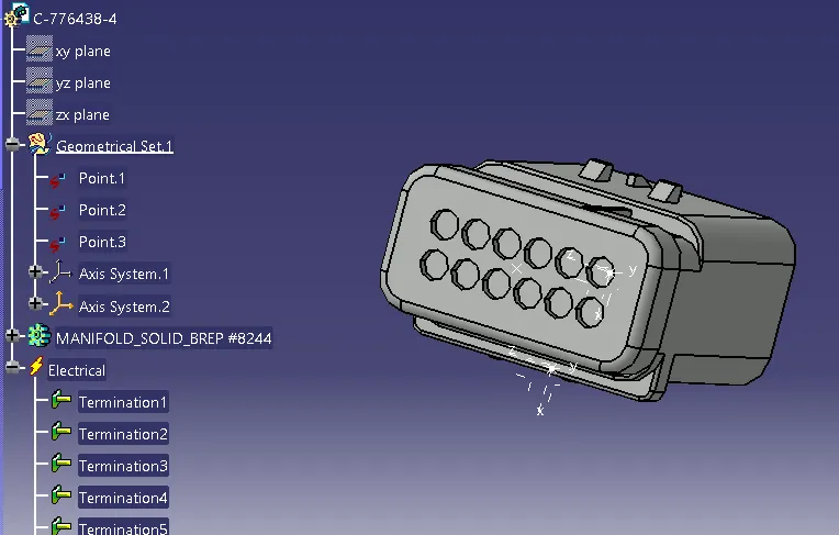
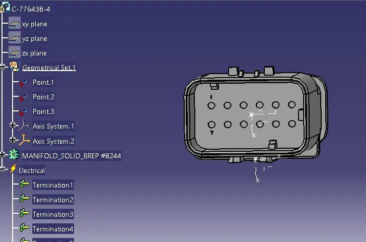
CONNECTORS (DEFINE MECHANICAL COMPONENTS INTO ELECTRICAL):
MOUNTING CLIP (DEFINE MECHANICAL COMPONENTS INTO ELECTRICAL):
FIR TREE CLIP:
Define the mechanical components electrically and prepare the catalogue for the same:
C-776438-4 (12 pole connector):
- Imported the STP file of the connector into Catia V5 and saved as a CATPART file.
- Switched to part design workbench and created points at the front face and mating face of the connector.
- Switched to electrical part design workbench and defined the connector electrically by using the command define connector.
- And also created the bundle connection point, connector connection point and the cavity connection point of the connector. And saved the connector file into the catalogue which is already created and saved into the device.
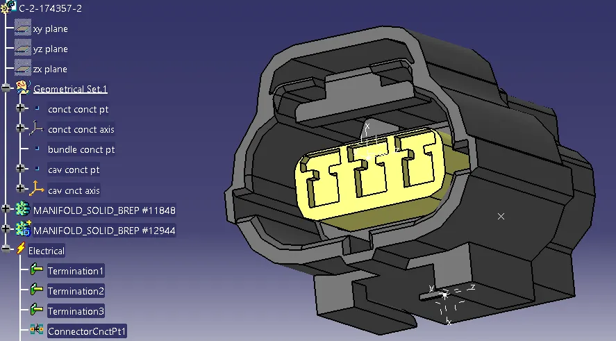
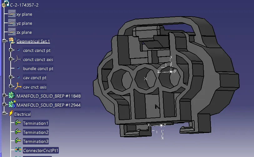
C-2-174357-2(3 pole connector):
- Imported the stp file of the connector into Catia V5 and saved as a CATPART file.
- Switched to part design workbench and created points at the front face and mating face of the connector.
- Switched to electrical part design workbench and defined the connector electrically by using the command define connector.
- And also created the bundle connection point and connector connection point of the connector. And saved the connector file into the catalogue which is already created and saved into the device.
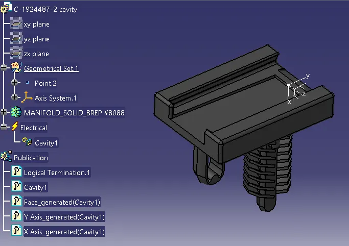
MOUNTING DEVICE:
- Imported the stp file of the mounting device and saved as a CATPART file.
- Switched to the part design workbench and created a point at the mating face of the mounting device. And also created the axis system the mating face.
- The mounting device is defined electrically by using the command called define equipment.
- And created cavity to the mounting device by using the command called define cavity. And saved the file into the catalogue.
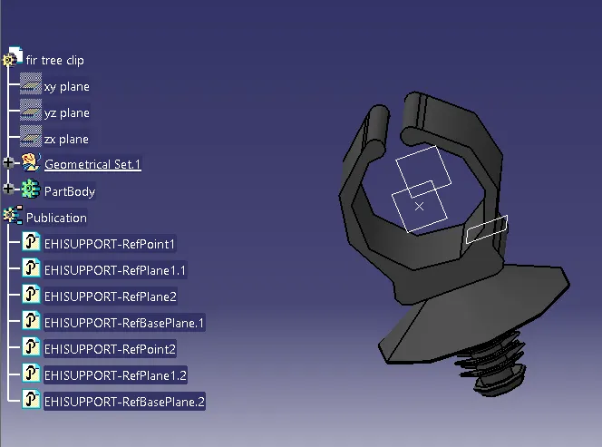
FIR TREE CLIP:
- imported the STP file of the fur tree clip and saved the file as a CATPART file.
- Switched to part design workbench and created the point at both sides of the clip as an entry point and exit point of the clip.
- And also created the planes at the points which we are created earlier as an entry plane and exit plane of the clip and base plane on the surface of the clip.
- Switched to the electrical part design workbench and defined the clip electrically by using the command Define support part and defined the first plane, second plane and base plane.
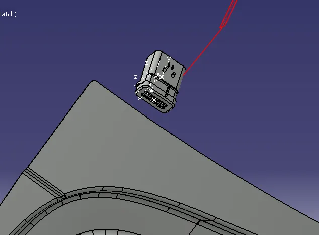
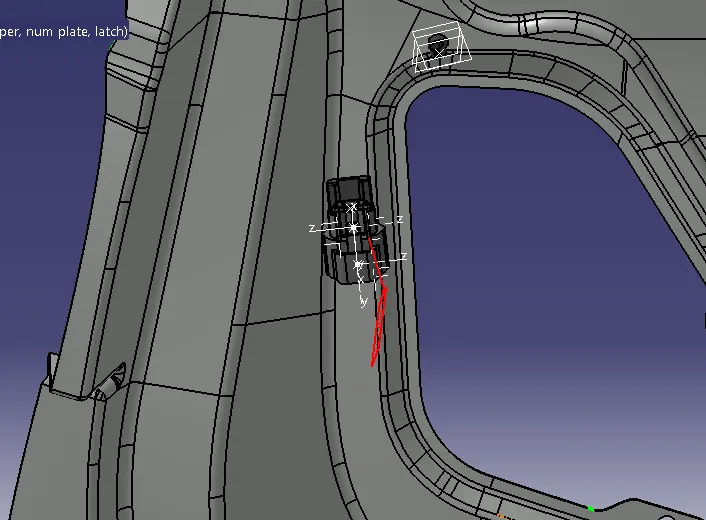
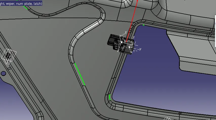
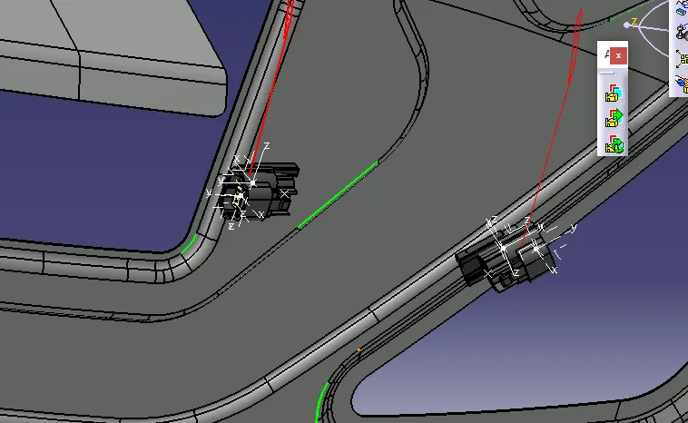
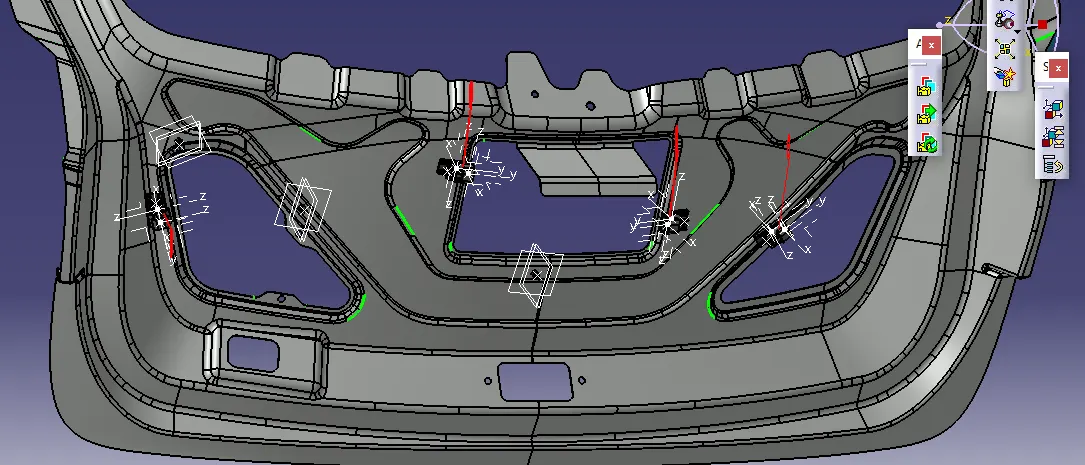
ALLIGNING CONNECTORS AND CLIPS TO THE BACK DOOR:
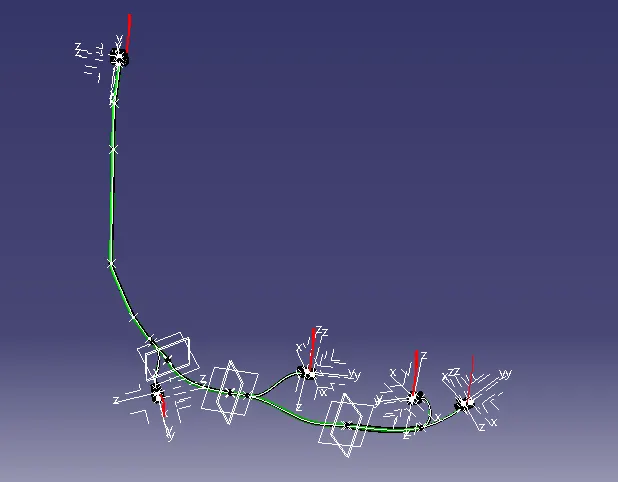
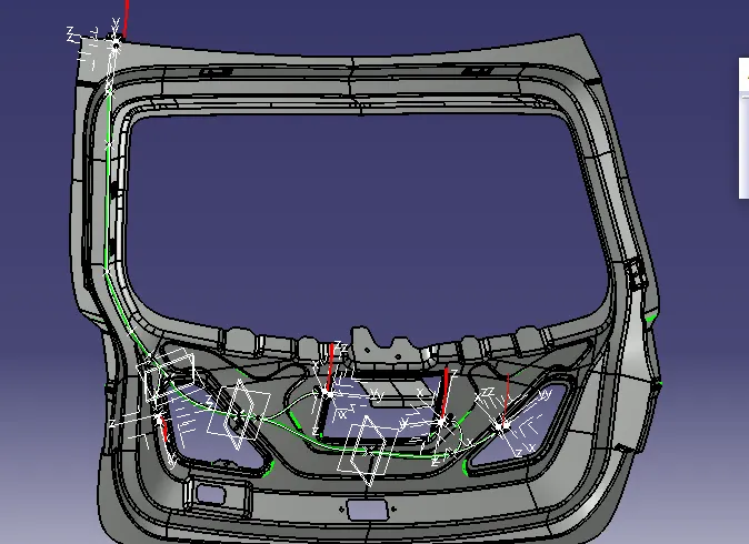
ROUTING THE WIRING HARNESS:
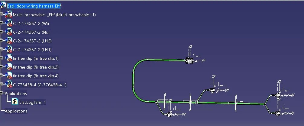
FLATTENING:
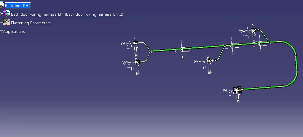
DRAWING FILE FOR WIRING HARNESS ASSEMBLY:
NOTE:
AS THE FILE SIZE IS SO LARGE IT IS NOT UPLODING THE FILE.
HERE I AM PROVIDING MY GOOGLE DRIVE LINK .
PLEASE GO THROUGH THE GOOGLE DRIVE LINK FOR THE GRADING.
GOOGLE DRIVE LINK:-
https://drive.google.com/file/d/1RQBuHVBiaG4a7IuIm1DIrT4m9z4YD6Bi/view?usp=drive_link