Project 2
PROJECT 2:
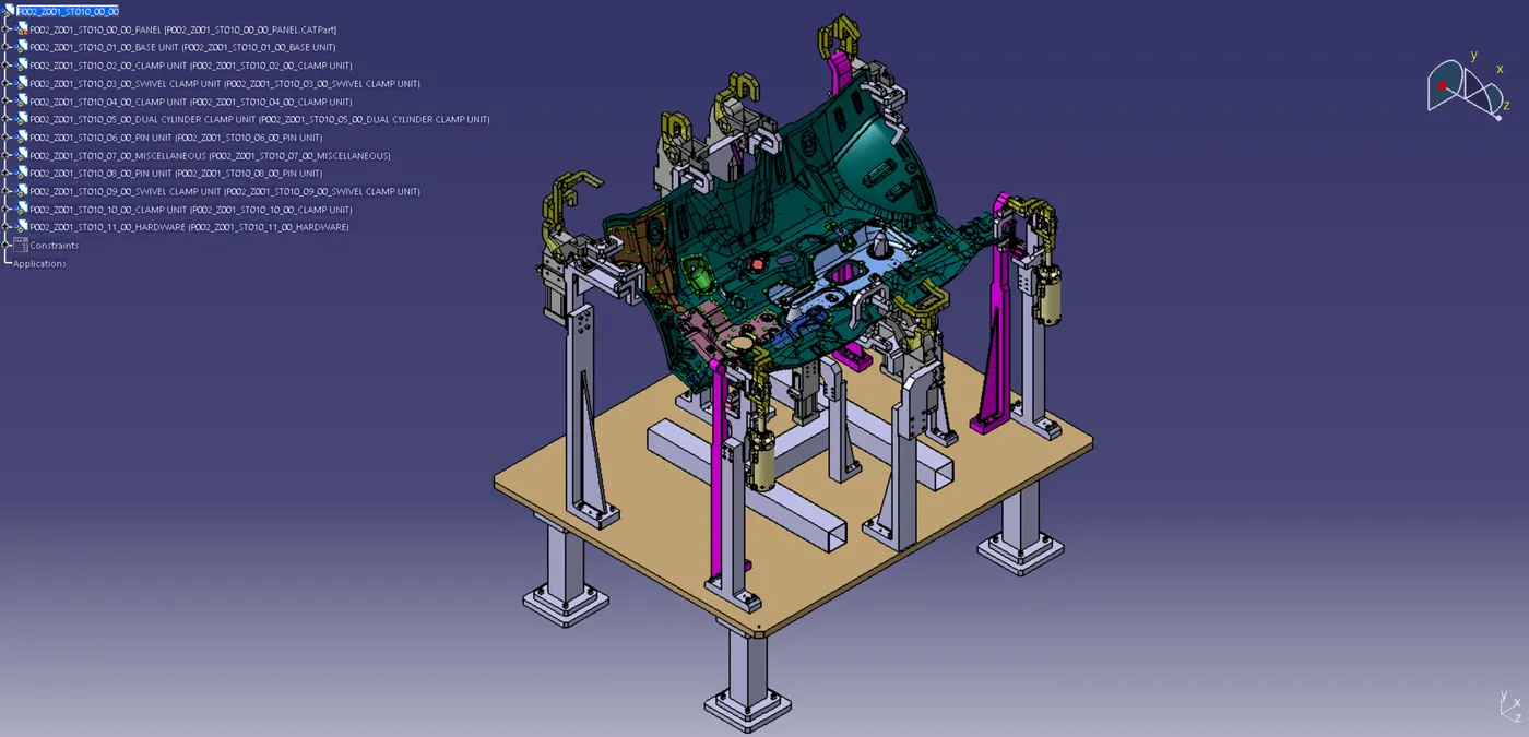
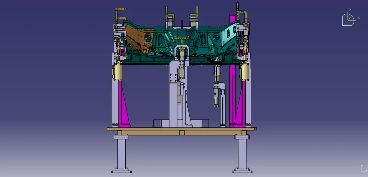
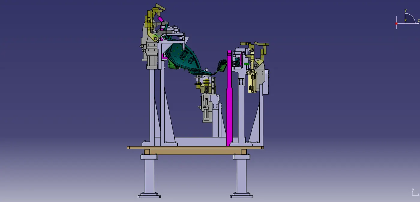
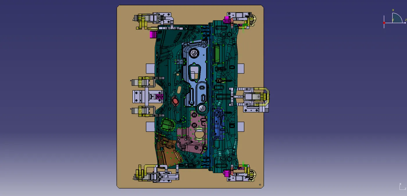
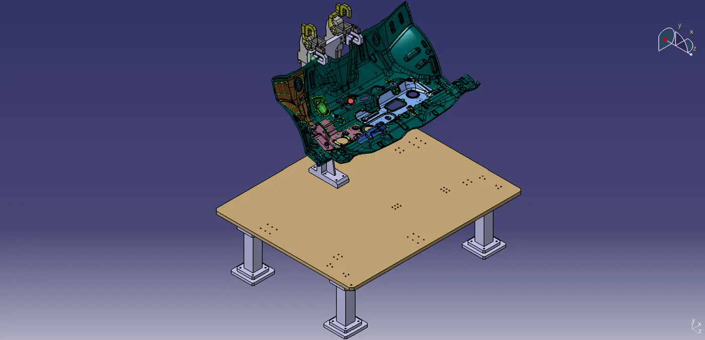
STEP 1: Gun Study
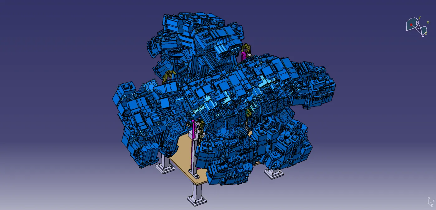
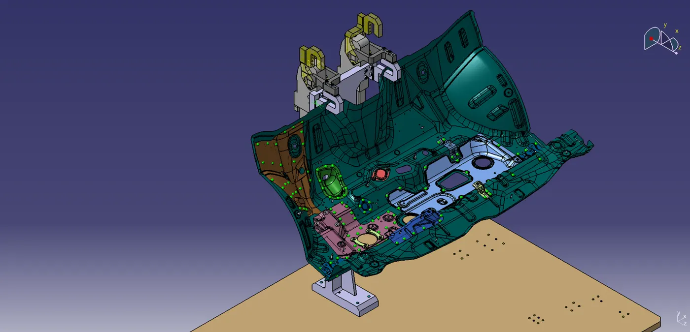
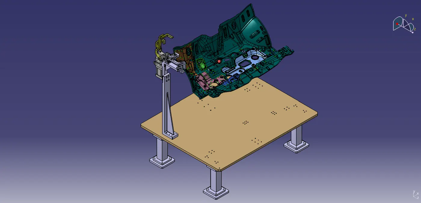
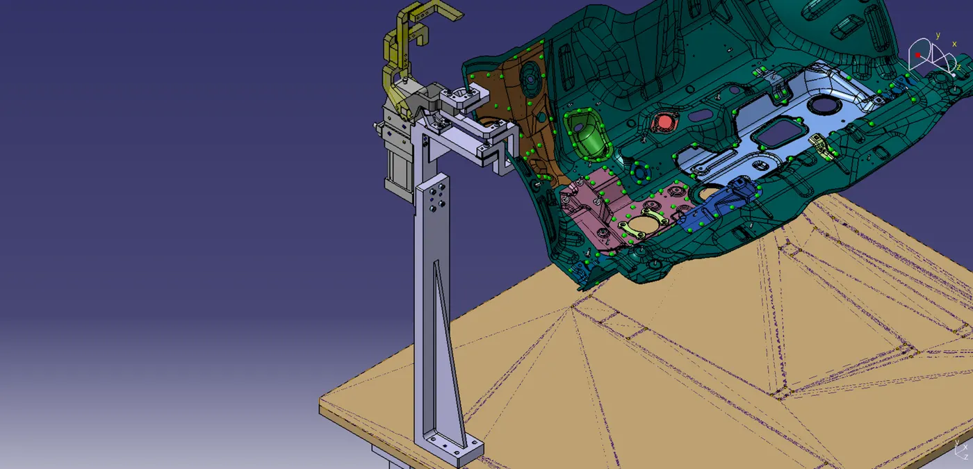
Weld gun study is done so that no fixture comes in way of weld gun during spot welding operation. This decides the placement of various units.
METHODOLOGY: Gun tip is placed on each spot and oriented normal to the weld surface. This is performed for each of spot presented such that it should not have any contact with either with different units or the panel which is to be welded.
STEP 2: Designing of Units
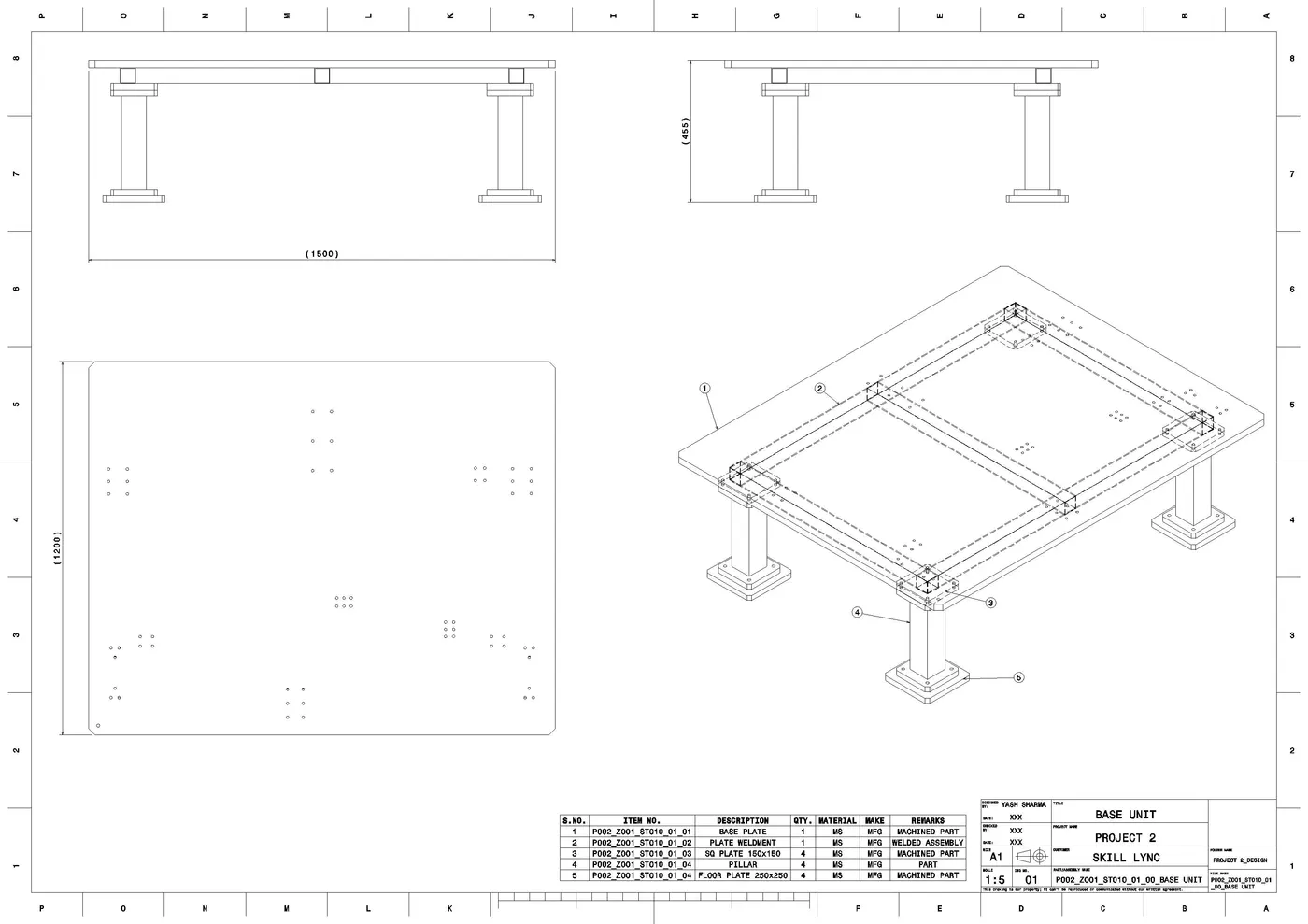
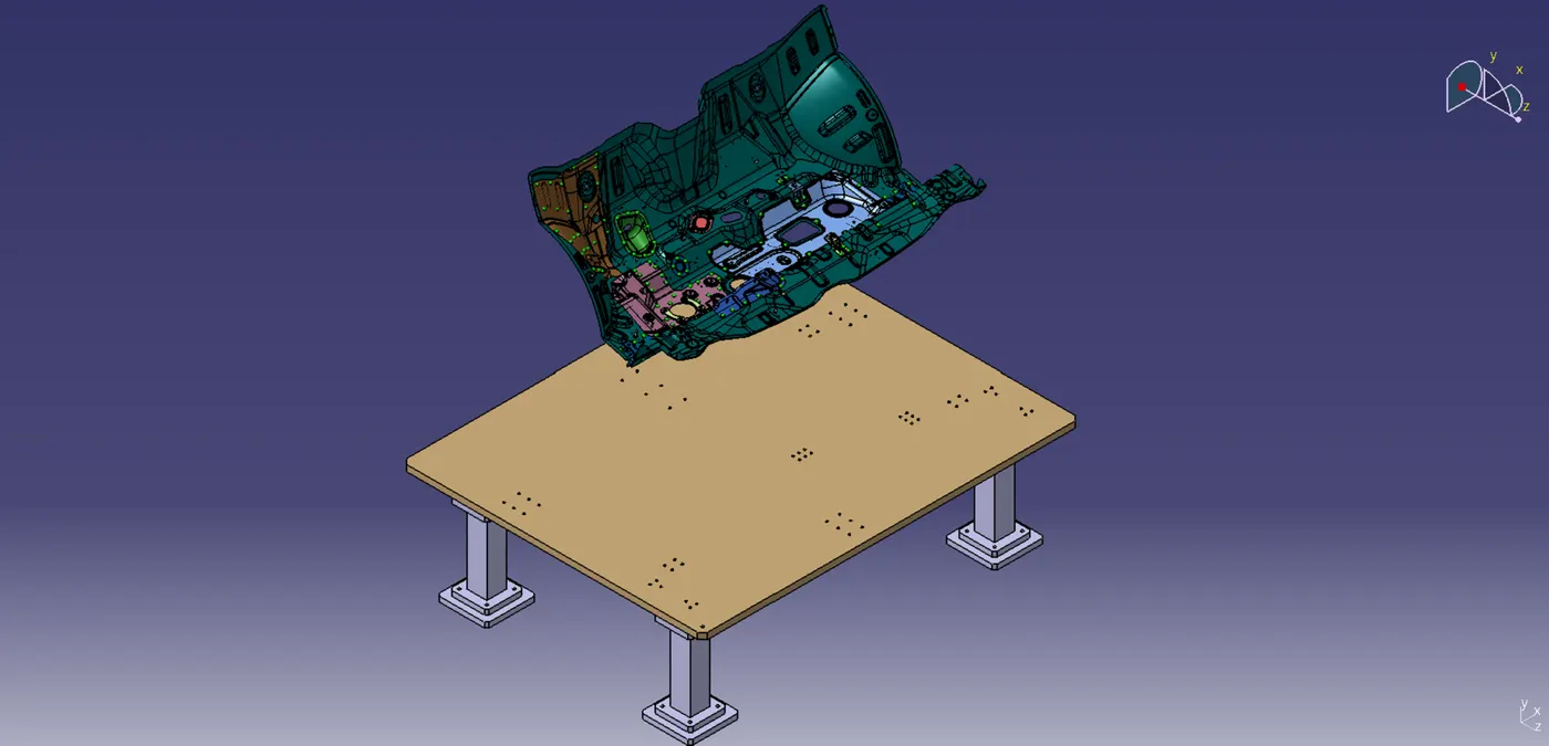
1. BASE UNIT:
Components:
- Base plate: Machined plate used for placing clamping units,pin units and other bodies.
- Base plate weldment: It Provide bending strength to the base plate.
Square tubes are welded to form a frame like structure which is welded to the Base plate. - Pillars: These are base unit legs which provide height to whole fixture assembly.
- Machined Sqaure plates: These are used in two places i.e. Welded at base plate weldment for attaching pillars to at interface between floor and pillar
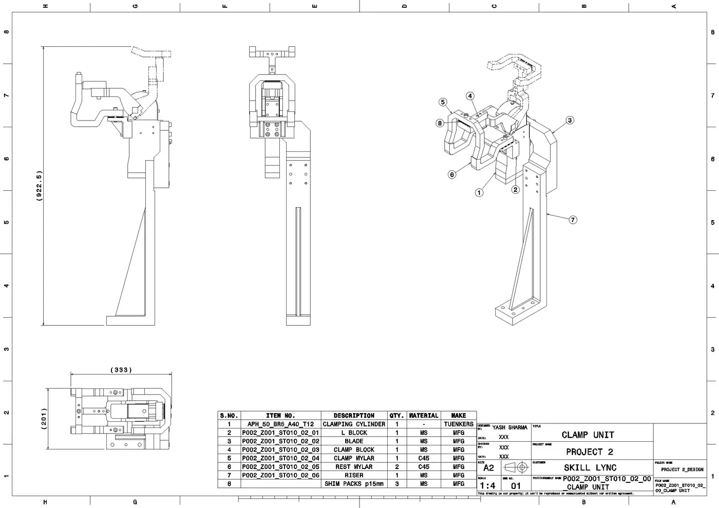
2. CLAMP UNIT:
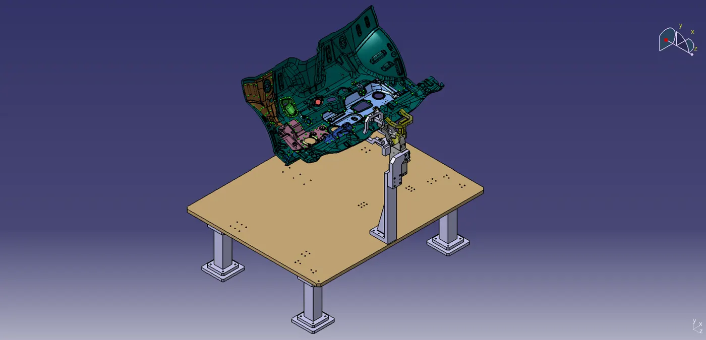
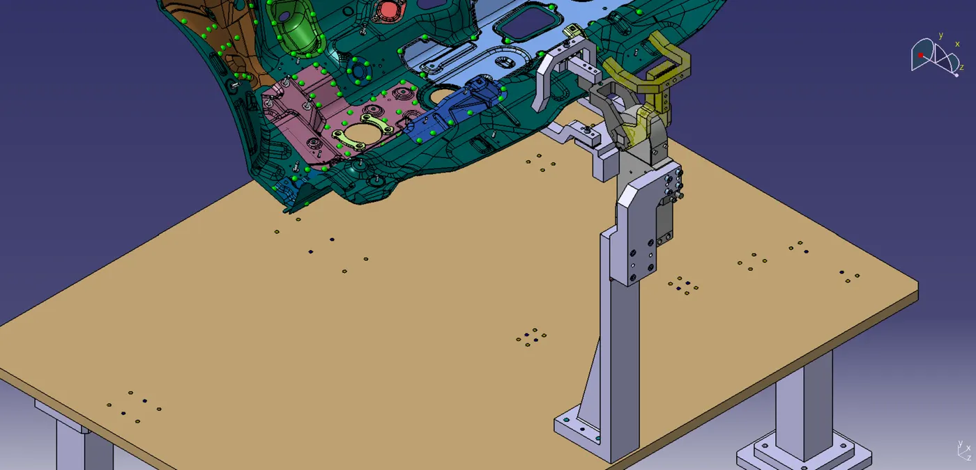
Components:
- Clamp cylinder
- Clamp mylar
- Rest mylars
- Blade
- Riser
- L block
- Shim packs
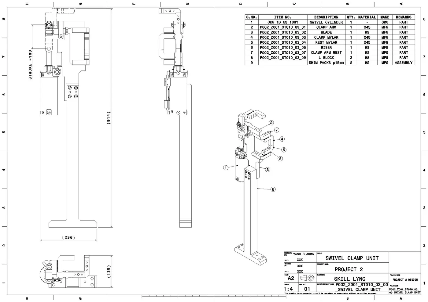
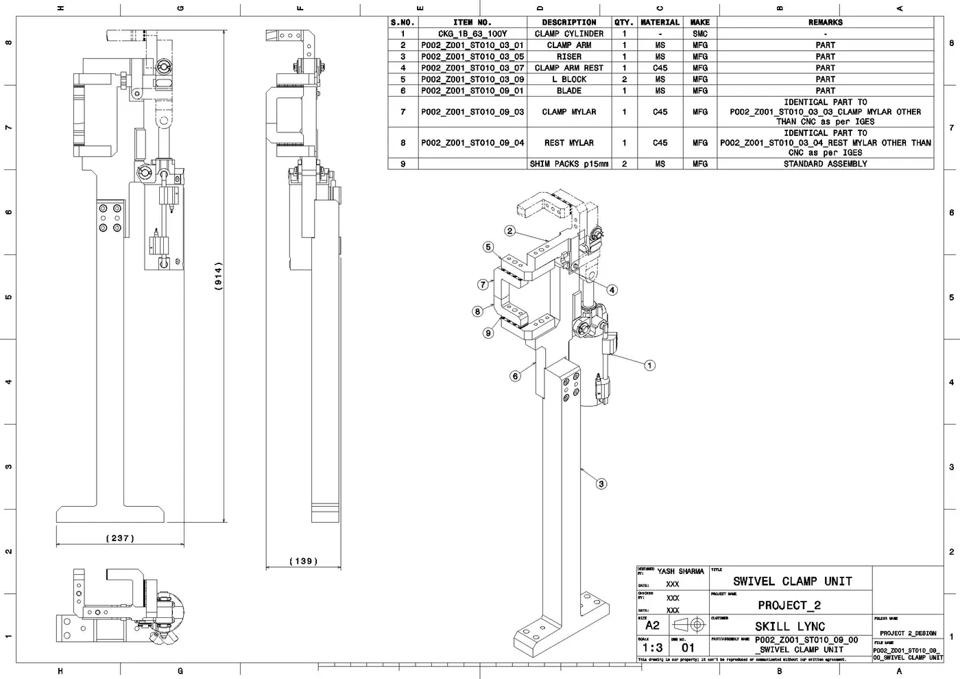
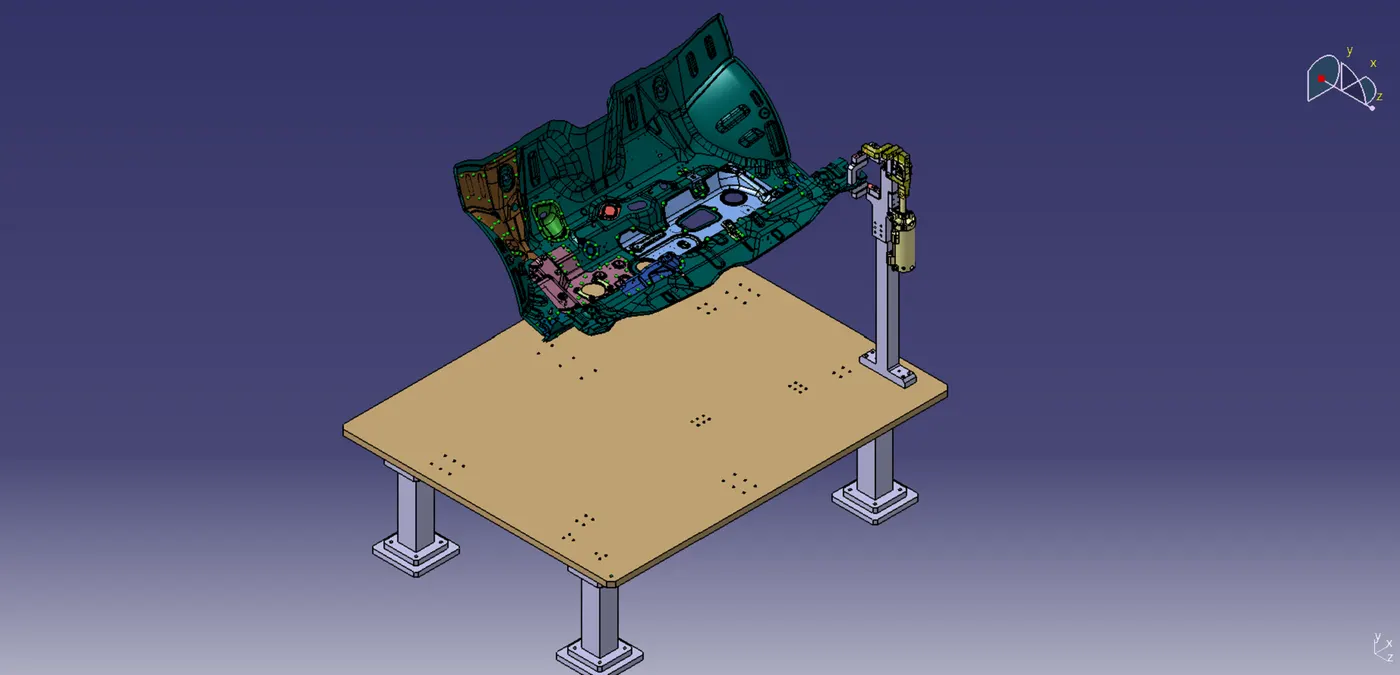
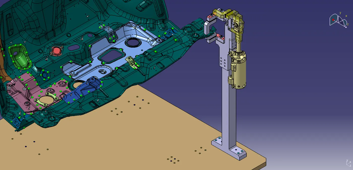
3. SWIVEL CLAMP UNIT:
Component:
- Swivel Clamp Cylinder
- Clamp Arm
- Clamp mylar
- Rest mylar
- L-blocks
- Blade
- Riser
- Shim Packs
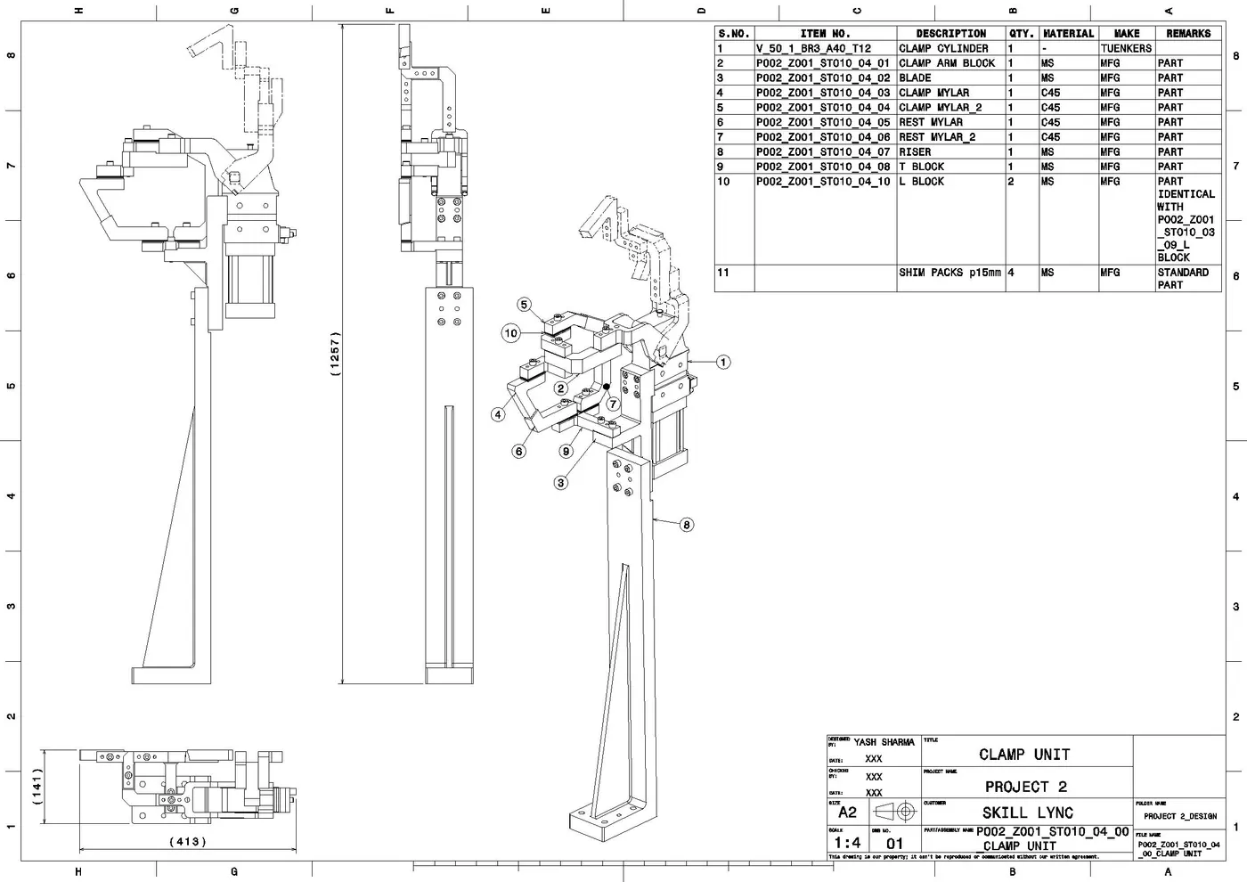
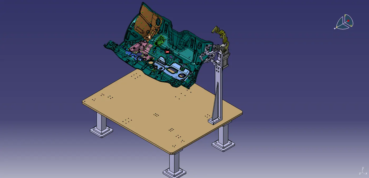
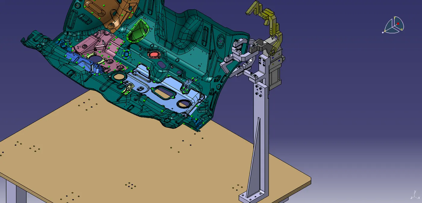
4. CLAMP UNIT:
Components:
- Clamp cylinder
- Clamp Mylars
- Rest Mylars
- Clamp Arm block
- L-Blocks
- T block
- Riser
- Blade
- Shim packs
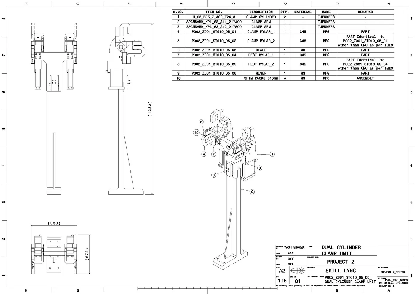
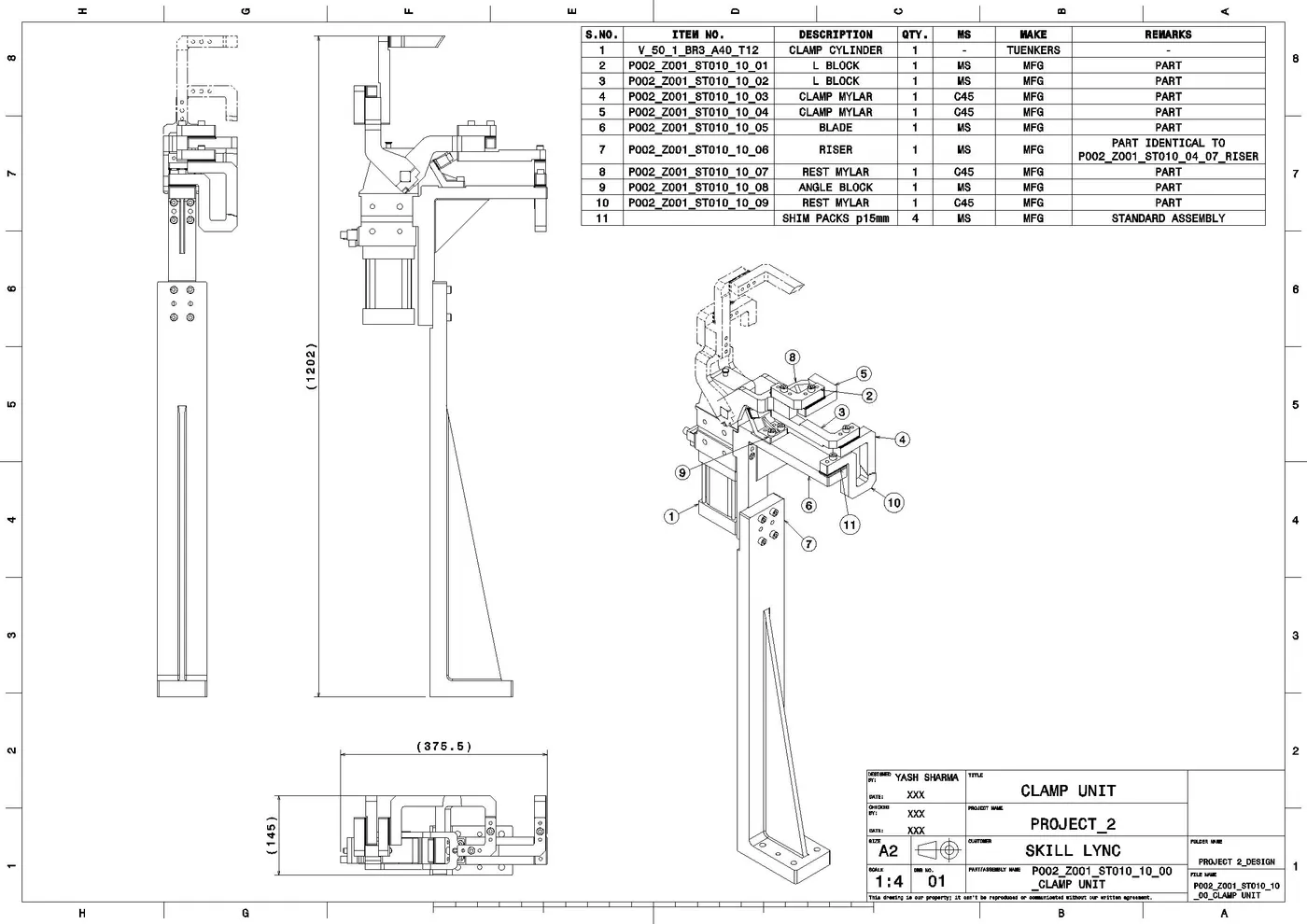
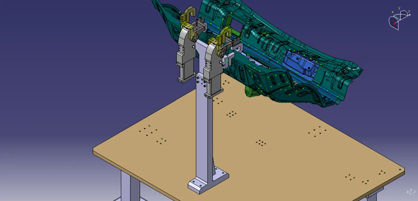
5. DUAL CYLINDER CLAMP UNIT:
Components:
- Clamp cylinders
- Clamp Mylars
- Rest Mylars
- L-Blocks
- Angle block
- Riser
- Blade
- Shim packs
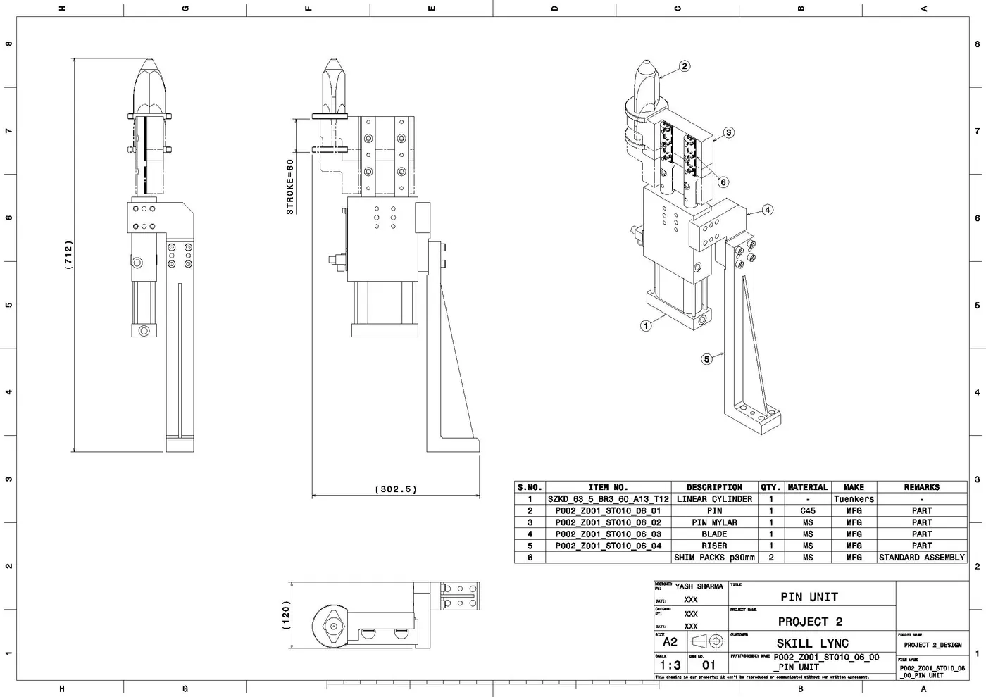
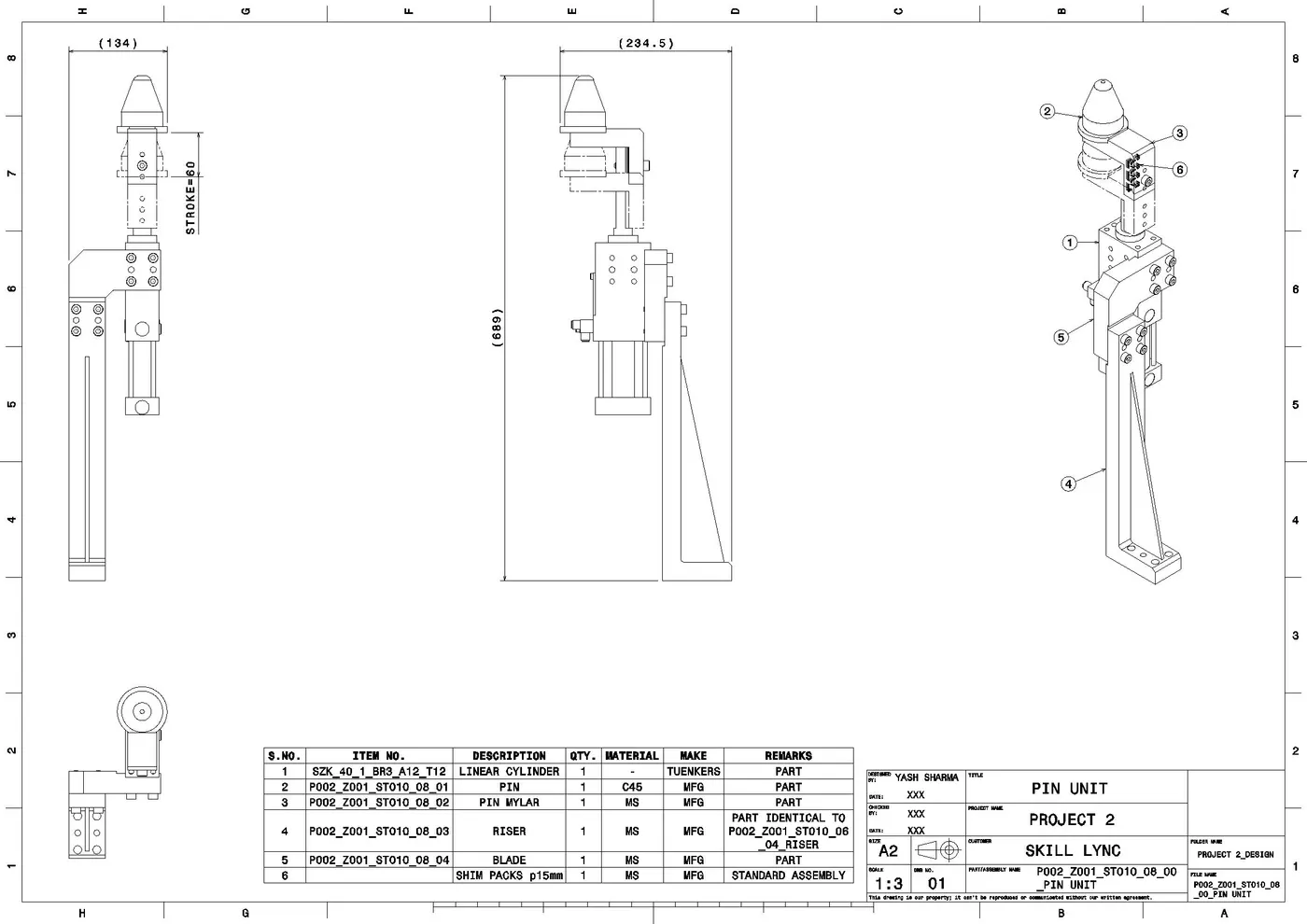
6. PIN UNIT:
Component:
- Linear cylinder
- Diamond shape Pin
- Pin mylar
- Blade
- Riser
- Shim packs
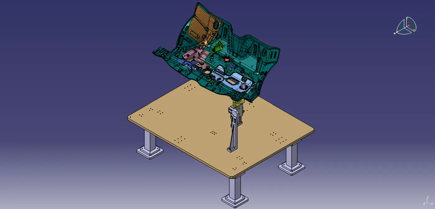
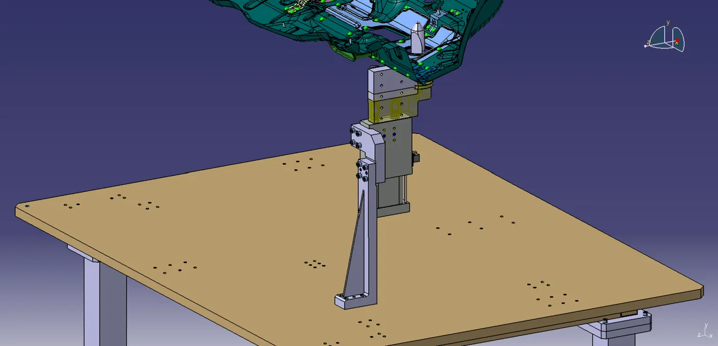
7. PIN UNIT:
Component:
- Linear cylinder
- Round shape Pin
- Pin mylar
- Blade
- Riser
- Shim packs
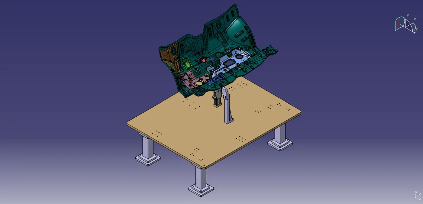
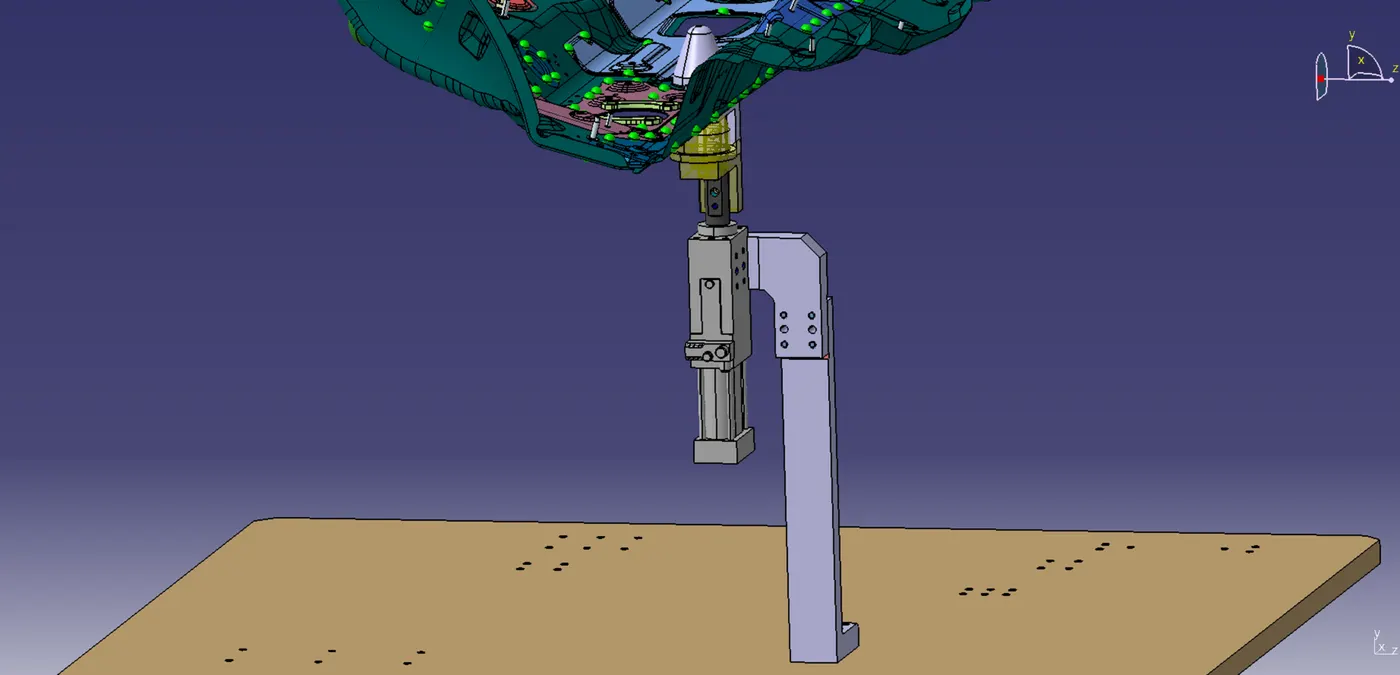
8. SWIVEL CLAMP UNIT:
Component:
- Swivel Clamp Cylinder
- Clamp Arm
- Clamp mylar
- Rest mylar
- L-blocks
- Blade
- Riser
- Shim Packs
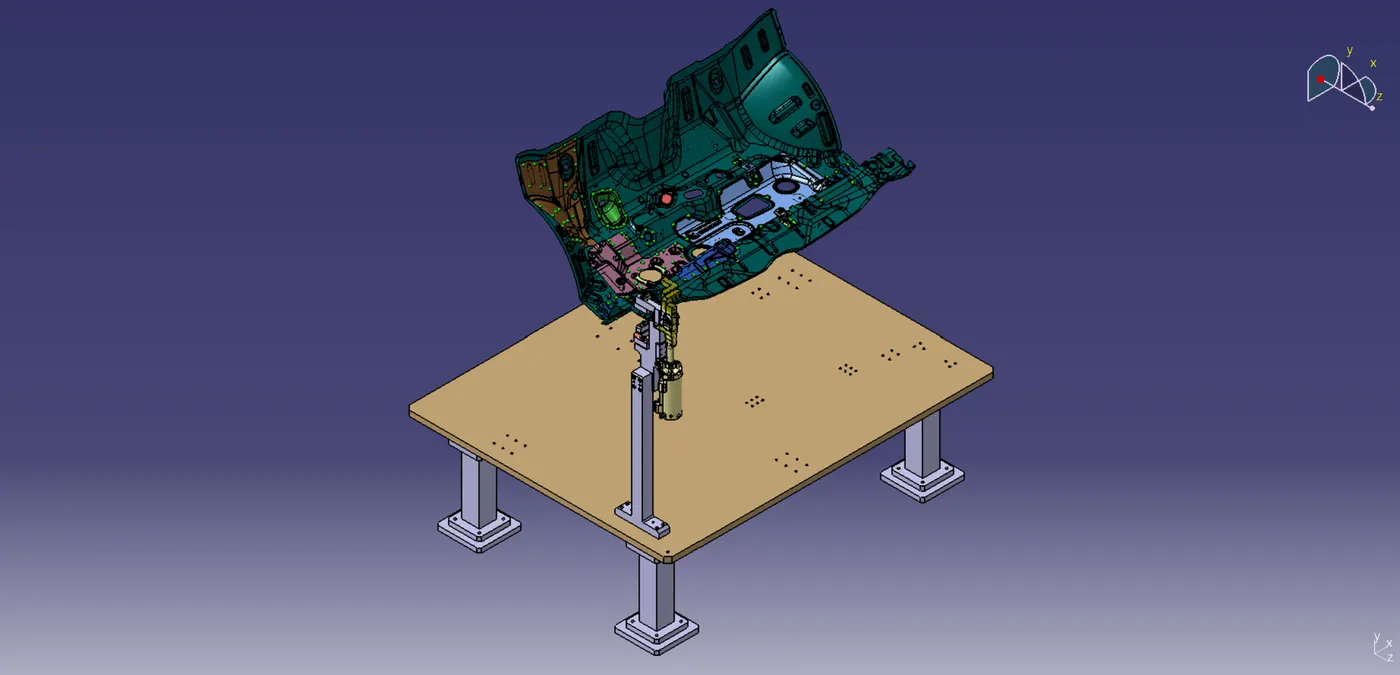
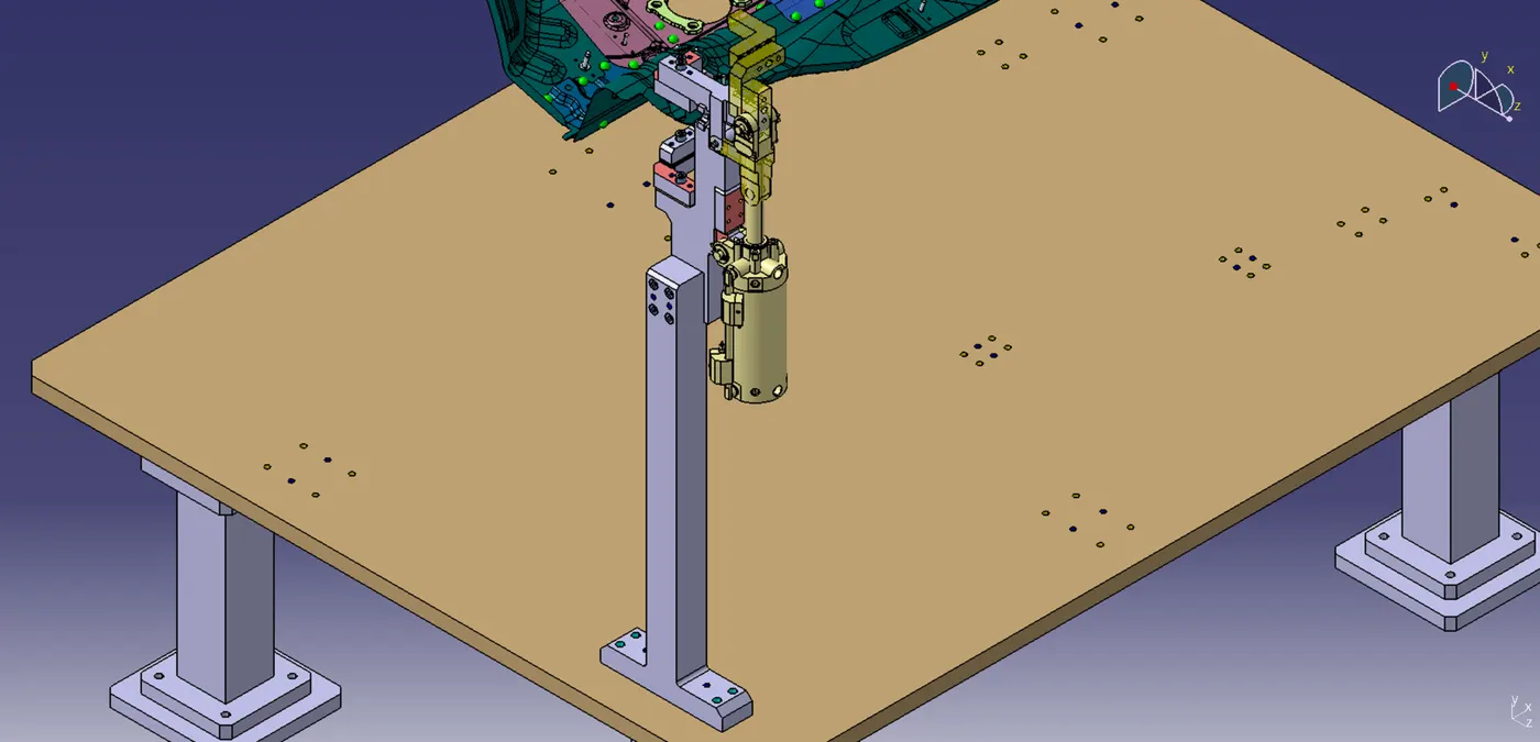
9. CLAMP UNIT:
Components:
- Clamp Cylinder
- Clamp Mylars
- Rest Mylars
- L-Blocks
- Angle block
- Riser
- Blade
- Shim packs
STEP 3: Miscellaneous Parts
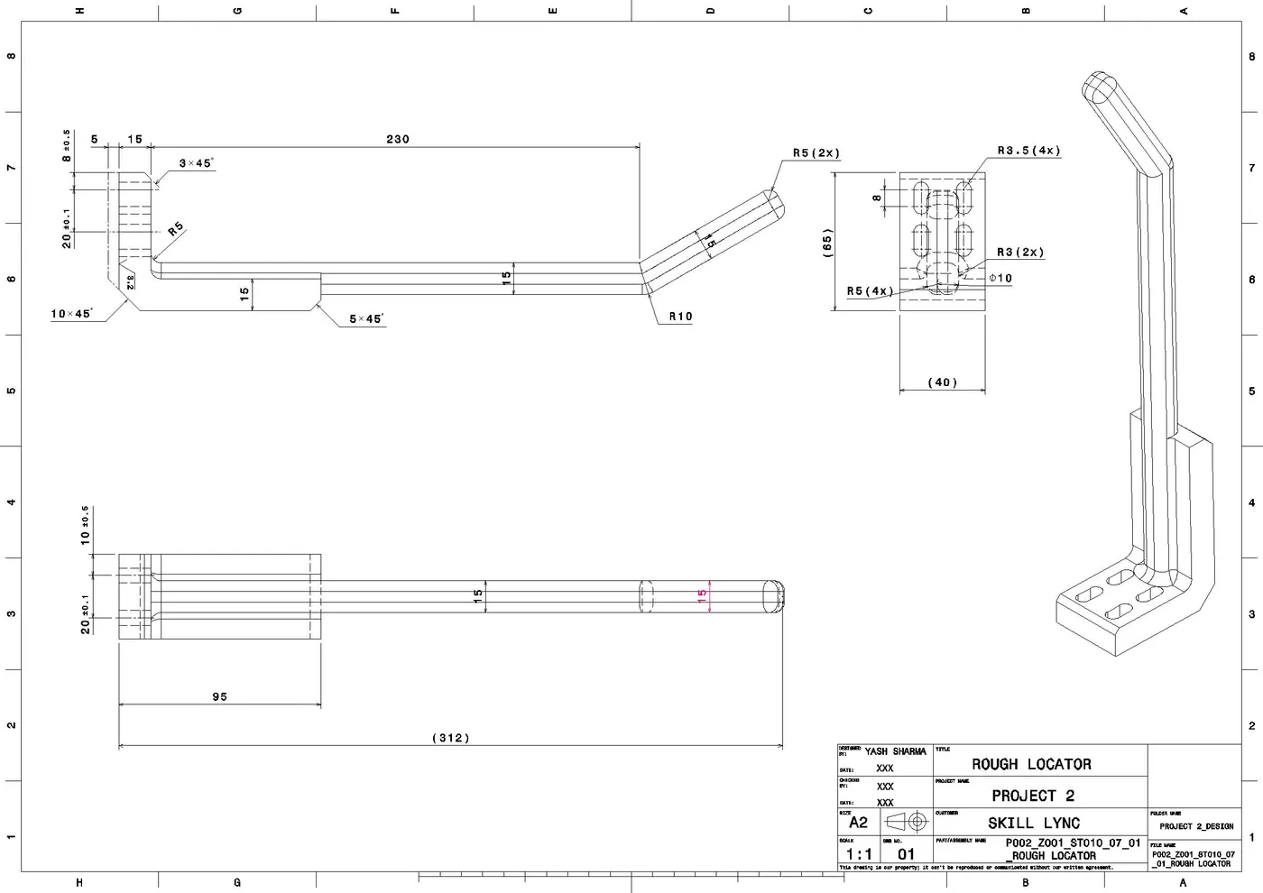
1. ROUGH LOCATORS:
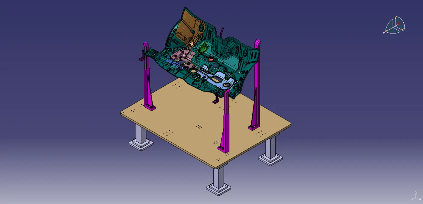
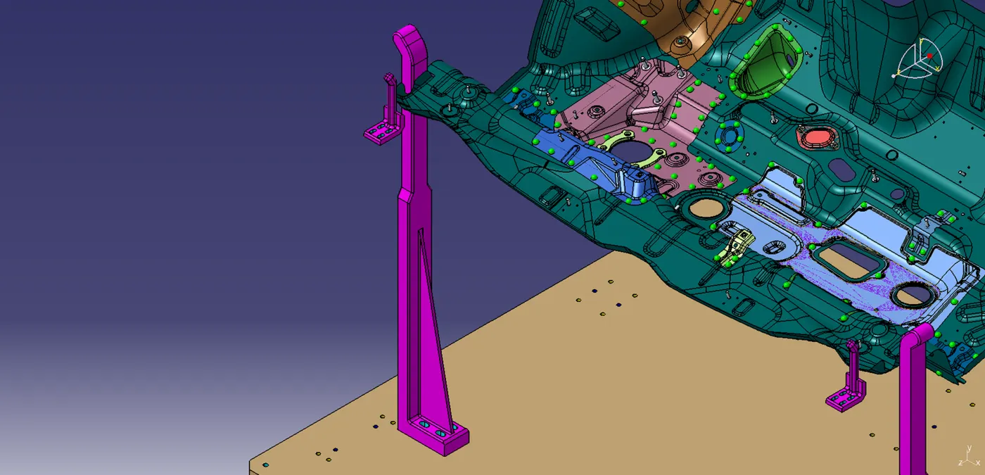
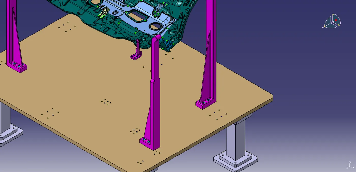
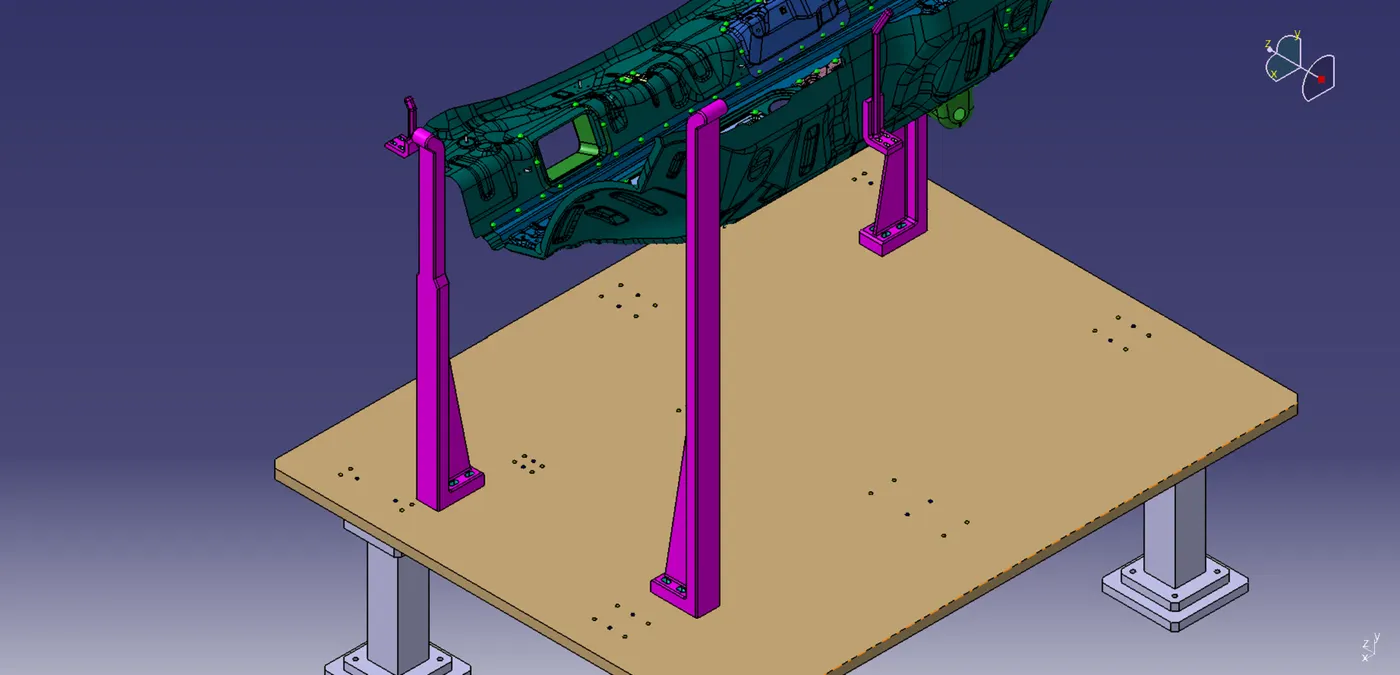
These are bodies placed around a panel for correct positioning of panel while placing for spot welding operation.
2. PNEUMATIC ROUTING:
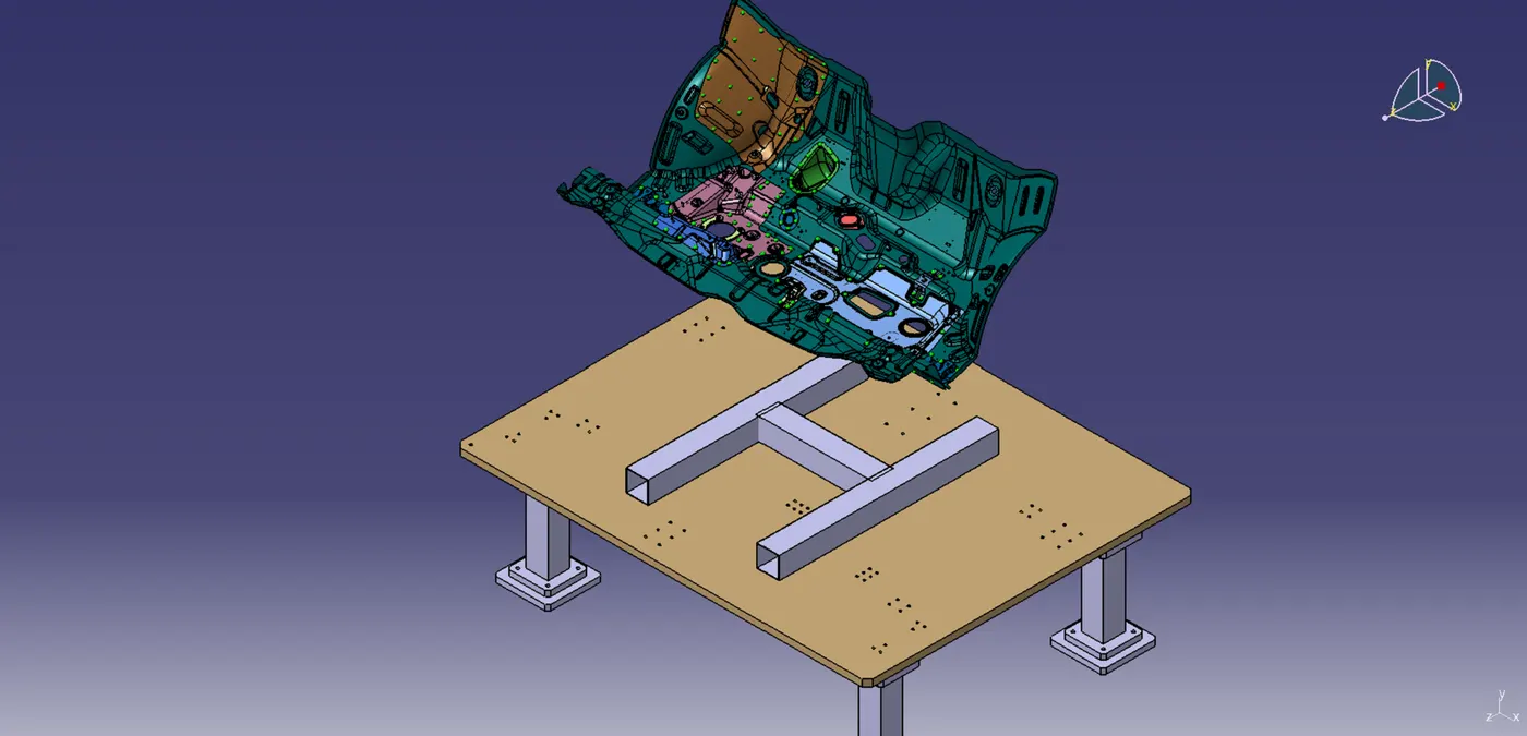
Pneumatic cables are passed through them so that they could be shielded from weld spatter. Weld spatter can create a cut on cable surface which can deterimental to fixture function.
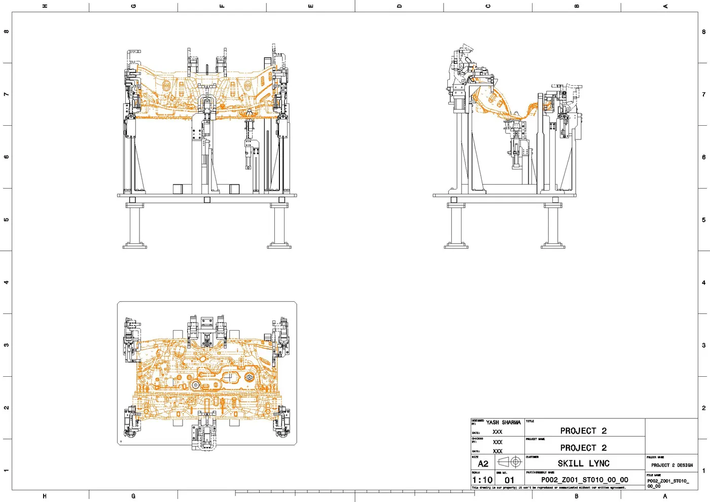
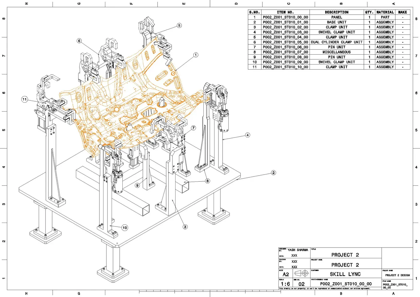
STEP 4: 2D Drawings