Project 2
1. Design a Warehouse Building located in Chennai using STAAD Pro Connect Edition. The specification must be as follows:
|
Width |
30m |
|
Length |
50m |
|
Eave Height |
9m |
|
Bay spacing |
6m |
|
Soil type |
Medium |
|
Safe Bearing Capacity |
200 kN/m2 |
|
Roof slope |
1 in 12 |
Assume suitable sections for structural elements. Follow IS800:2007, IS1893 and IS 875
- Prepare a Design Basis Report for the project
- Create structural model using STAAD Pro Connect Edition
- Prepare DL, LL, WL and EQL load calculations as per IS 875 standards
- Design using MS – Excel
- Steel column
- Rafter
- Base plate
- Pedestal
- Z- purlin
- Design Foundations using STAAD Foundation.
- Attach necessary sketches and drawings wherever required.
- All stipulations, assumptions and design parameter must adhere to Indian Standards.
INTRODUCTION:-
In this project I will design a Warehouse Building located in Chennai, where plan dimension is 30m in width and 50m in length, eave height is 9m and bay spacing is 6m, roof slope is 1 in 12. Beside this, the soil type is medium soil and safe bearing capacity of soil is 200 KN/m2. Moreover, I have used serveral Indian codal provision like- IS-800 : 2007, IS-808, IS-1893, IS-875 etc while executing the design. Apart from that, I used excel file while design steel column, rafter, base plate, pedestral, Z-purlin.
AIM:-
To Design a Warehouse Building located in Chennai using STAAD Pro Connect Edition. Then prepare detailed reports of that project
TOOL AND COMMAND:
- Geometry
- Property
- Loading
- Supprots
- Analysis
- Design
- Run analysis
- Analysis command
- Command file
- Annotate
- Displacement,Fy,Mz
PROCEDURE:-
1) Prepare DL, LL, WL and EQL load calculations as per IS 875 standards
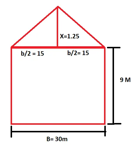
A) Calculation of ridge height:-
Given data-
Width = 30m
Height = 9m
Length = 50m
Bay spacing = 6m
- Calculate the central ridge height if roof slope is 1 in 12
- Lets assume ridge height is "X".
As per formula
X/(b/2) = 1/12
. '. X/(30/2) = 1/12
X = 15/12
X = 1.25 m
B) Calculation of Dead load:-
Self weight of structure:-
Factor of safety = 1.15
UDL on Rafter (Main frame):-
Weight of roof sheeting = 5 Kg/m2
Weight of sag rods and braces = 5 Kg/m2
Collateral load = 10 Kg/m2
Total load = 20 Kg/m2 = 0.2 KN/m2
UDL on Rafters:-
Bay spacing = 6m
UDL = 0.2 X 6 = 1.2 KN/m
UDL on Rafters from purlin:-
Choose suitable purlin section for weight of purlin (IS-811)
Say Z = 270 X 75 X 20 X 2.55 = 8.77 Kg/m
weight on rafters from purlin = (Number of purlin X Length of purlin)/Length of rafter
= ( 5 X 6 X 8.77)/15
= 17.54 Kg/m = 0.175 KN/m
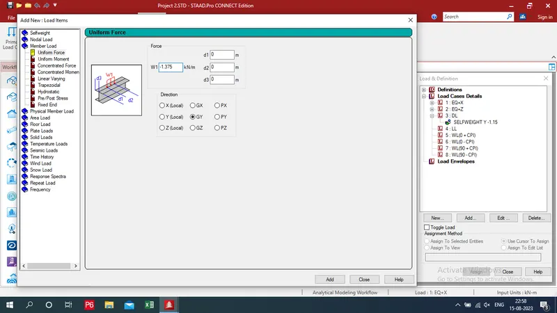
UDL on main frame = 1.2 + 0.175 = 1.375 KN/m
UDL on gable frame = 1.375/2 = 0.687 KN/m
UDL on Column (Main frame):-
Weight of side wall sheeting = 5 Kg/m2
Weight of sag rod and braces = 5 Kg/m2
Load from sag rods & braces = 10 Kg/m2 = 0.1 KN/m2 = 6 X 0.1 = 0.6 KN/m
Weight of grit (270 X 75 X 20 X 2.55) = 8.77 Kg/m
Weight on column = (5 X 6 X 8.77)/6 = 43.85 Kg/m = 0.438 KN/m
Total Load = 0.6 + 0.438 = 1.038 KN/m
UDL on Column (Gable frame):-
Total load = 1.038/2 = 0.565 KN/m
Load on wind column:-
Load from sheet and sag rods = 0.1 X 6 = 0.6 kN/m
Weight of grits (230 X 75 X 20 X 2) = 6.32 KG/m
Load on wind column = (6X 6.32 X 6)/6 = 37.92 Kg/m = 0.38 KN/m
Total load = 0.6 + 0.38 = 0.98 KN/m
Dead Load on eave strut & Gutter:-
Point load:-
Weight of Eave strut = CS 270 X 75 X 20 X 3.15 = 10.7 Kg/m
Weight of eave gutter = 0.25 X 0.25 X 0.001 = [0.25 + 0.25 + 0.25] X 0.001 X 7850 =5.89 Kg/m
Load due to eave strut & gutter = 10.7 + 5.89 = 16.59 Kg/m
Load due to eave strut & gutter (Main frame) = 16.59 X 6 = 99.54 Kg = 0.995 KN
Load due to eave strut & gutter (Gable frame) =0.497 KN
C) Calculation of Live load:-
Live load on roof = 0.75 KN/m2 (IS 875- II)
UDL on Rafter:-
Main frame rafter = 0.75 X 6 = 4.5 KN/m
Gable frame rafter = 0.5 X 4.5 = 2.25 KN/m
Eave gutter (250 X 250 X 1mm)
Load due to weight of water in gutter:-
Main frame = [0.25 X 0.25 X 9 X 6] = 3.375 KN
Gable frame = [0.5 X 3.375] = 1.687 KN
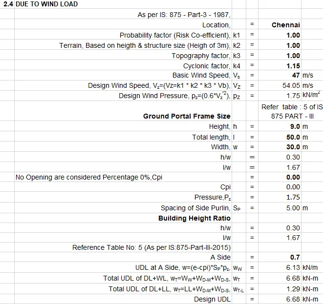
D) Calculation of wind load:-
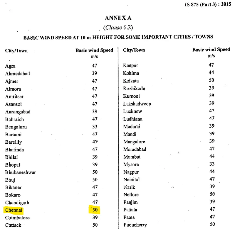
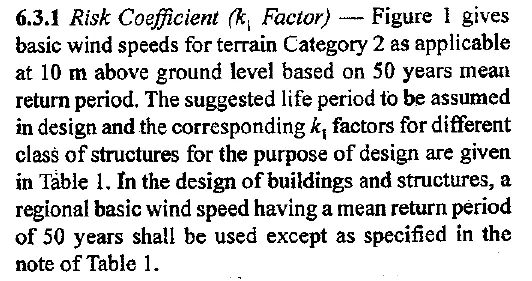
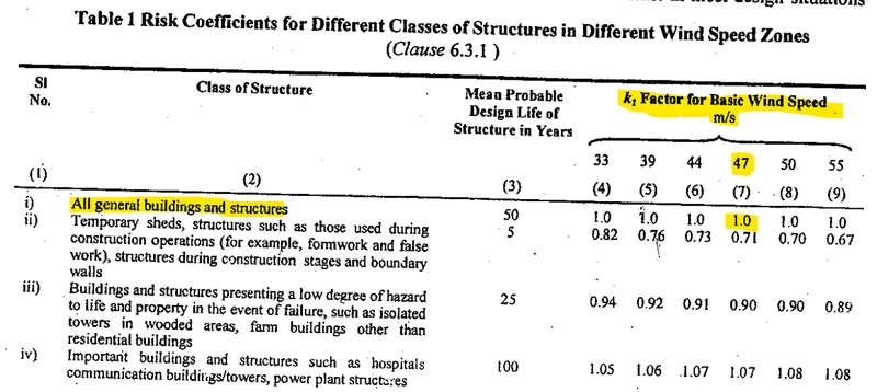
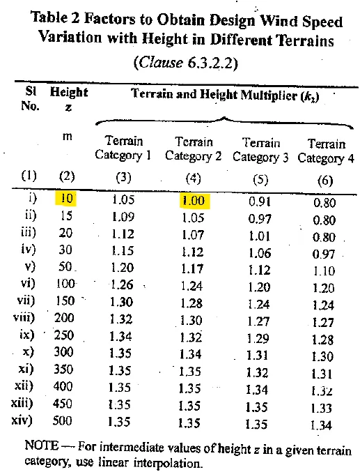
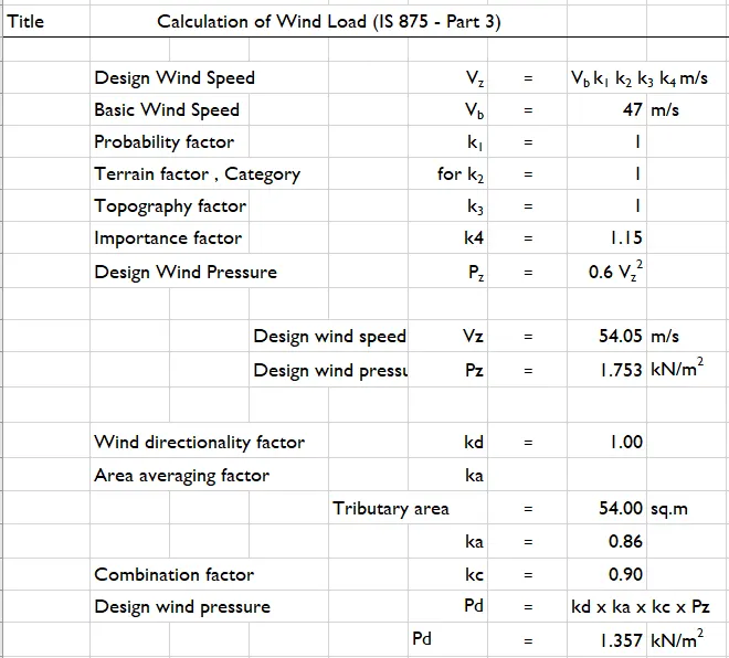
Value of K2 will be taken as 1
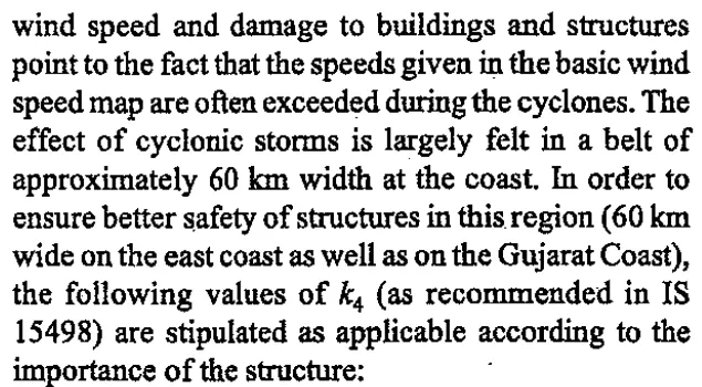
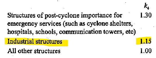
As Chennai falls under cyclonic region the value of K4 will be taken as 1.15

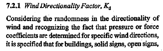
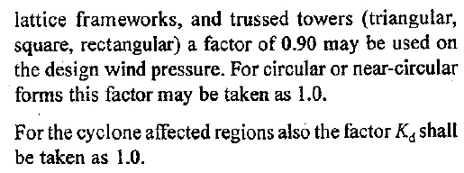
As Chennai is in the East coast of India, thus it will be considered in cyclone affected area and value of Kd = 1
Then we calculate Tributery area as = (C/C bay distance X Height of the shed) = (6 X 9)= 54 sqm.
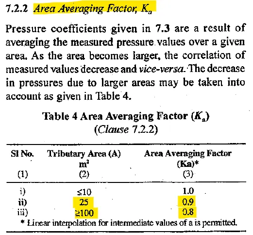
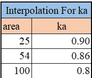
We will take the value of Ka = 0.86 by interpolation method
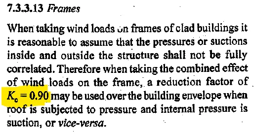
We will take the value of Kc is 0.90
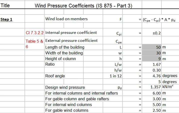
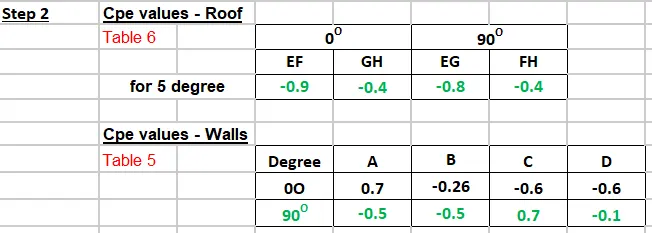
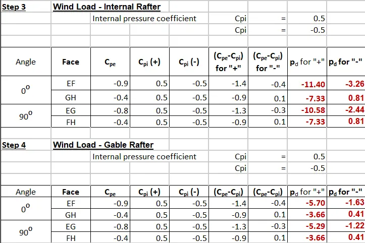
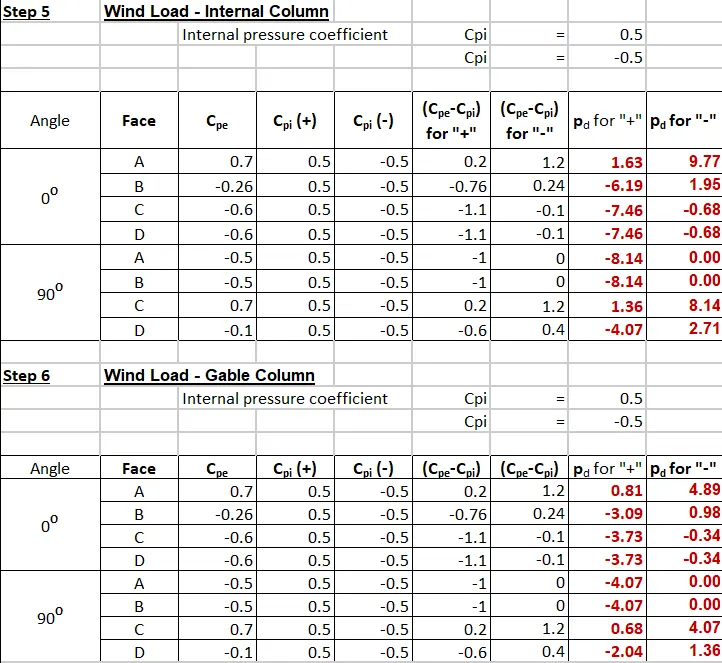
Now, Calculate the wind load in MS Excel
2) Create structural model using STAAD Pro Connect Edition
Step:1 Open Staad pro:
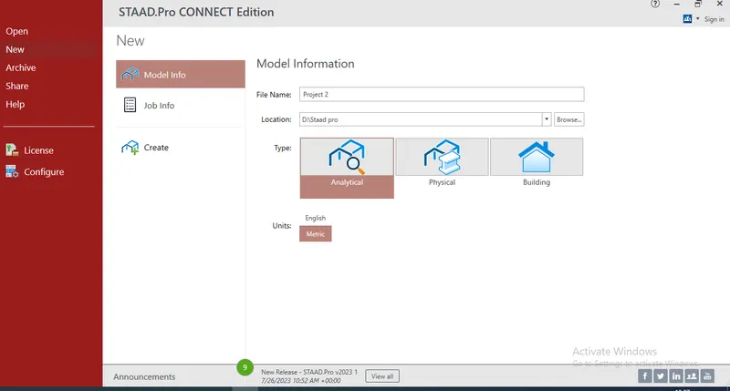
- First open the staad.pro software and fill all the project details and select the model as analytical .
- Then select unit system as Metric.
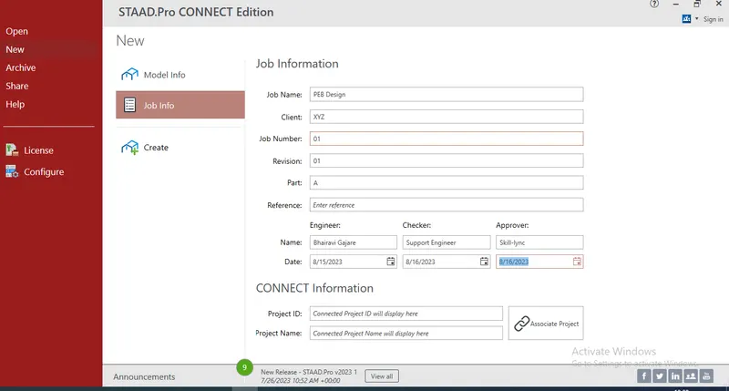
- Then provide Job Info - Create
Step 2: To Draw Geometry:
a) Draw gable and main frame
- Draw nodes at distance 0,15 and 30 m
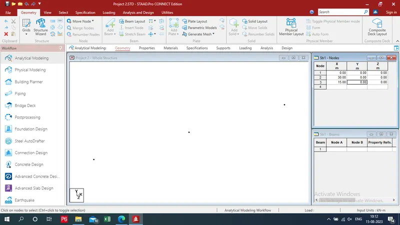
- Then by using TR Command draw gable column at height 9m and 10.25m
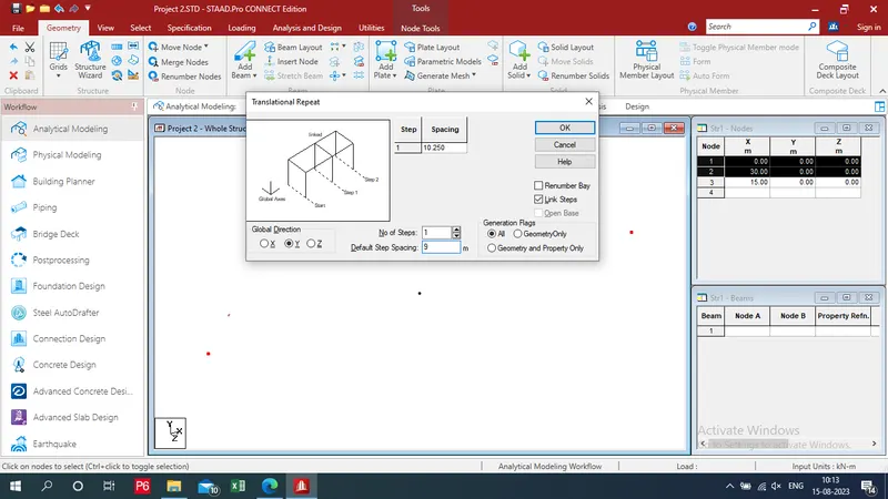
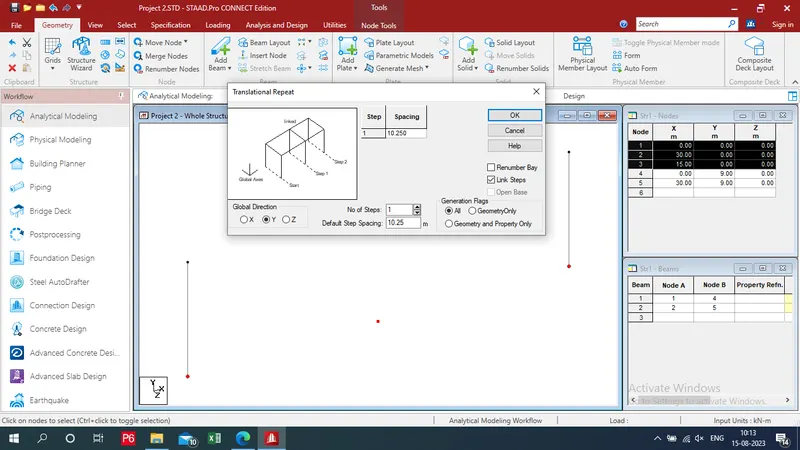
- Join them by using beam commnad
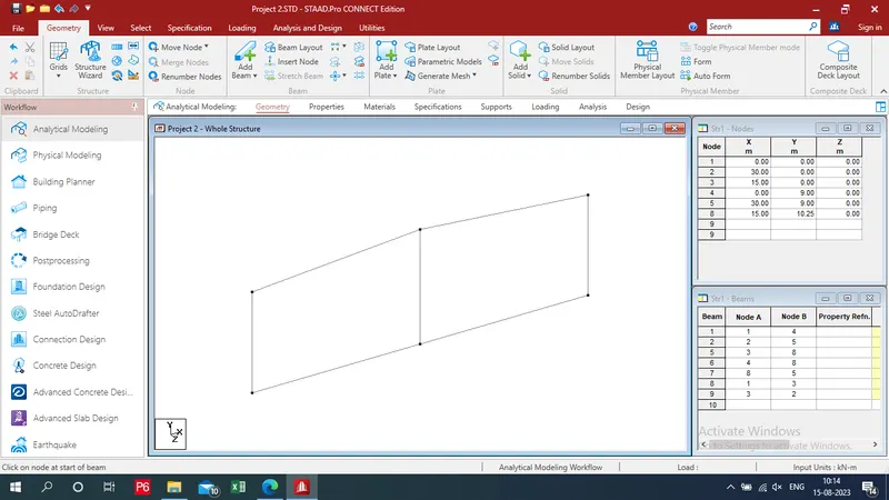
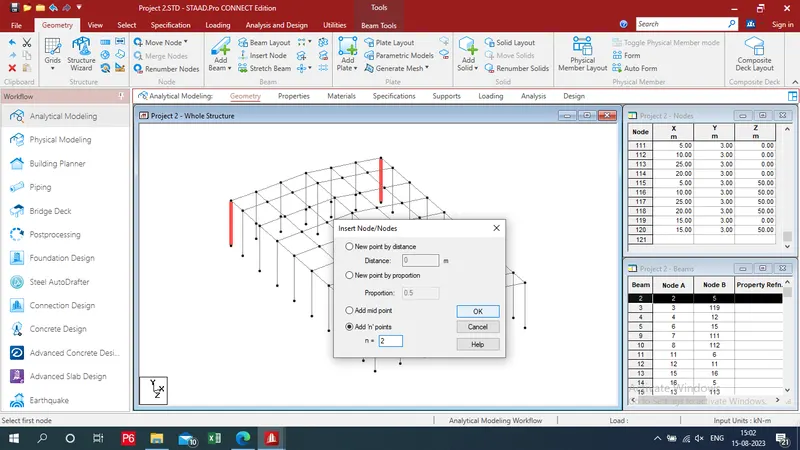
- Select bottom beam of left side - click on insert node
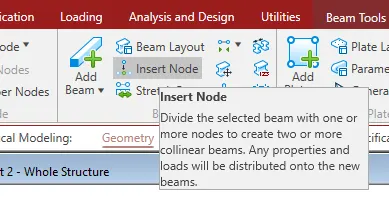
- provide n = 2 - Add N point ok
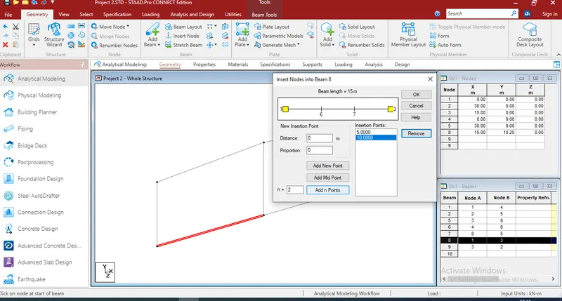
- Draw column by using TR
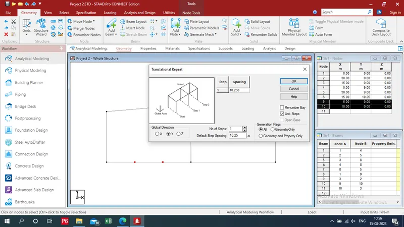
- Make Seperate intersect beams - delete them
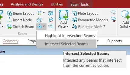
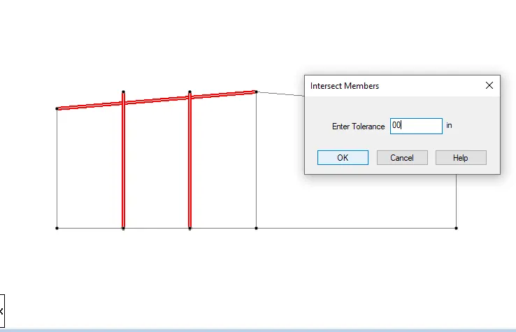
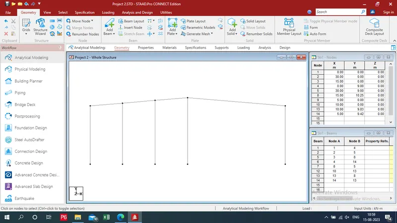
- Draw similar beams at another side
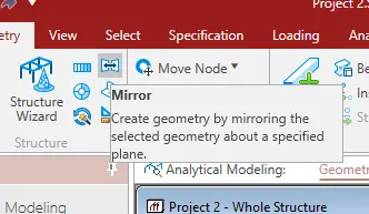
- Gable farme is created
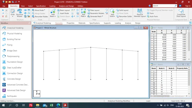
- Draw main frame by using TR having spacing is 4m from gable frame and 6m from main frame in Z direction
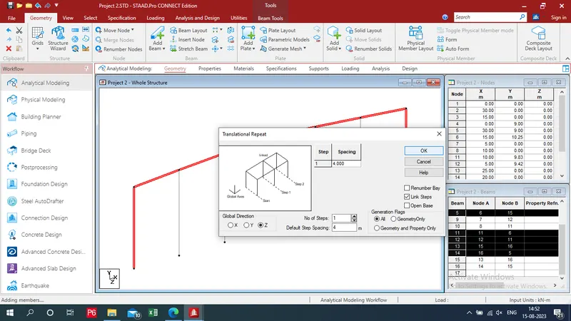
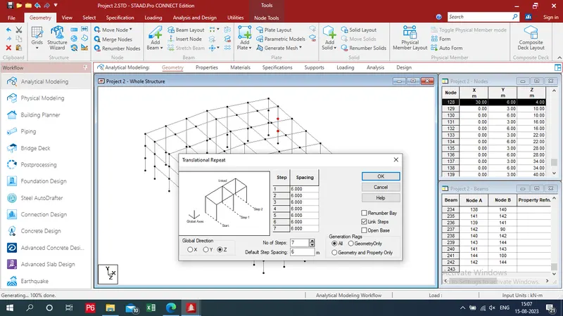
- structure Frame is created
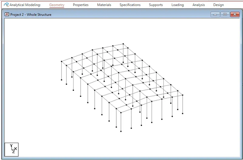
- Provide dimension to structure
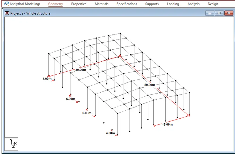
b) Provide nodes:
upto height of cladding 3m from bottom and top bracing 3m from top
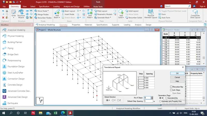
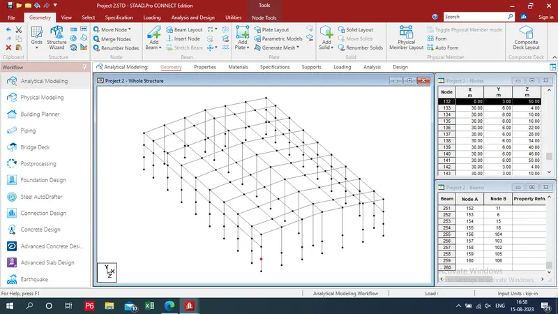
- Provide annotation
c) Draw Bracing
- By using add beam, TR and mirror command draw bracing
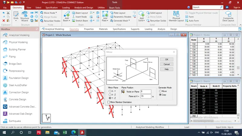
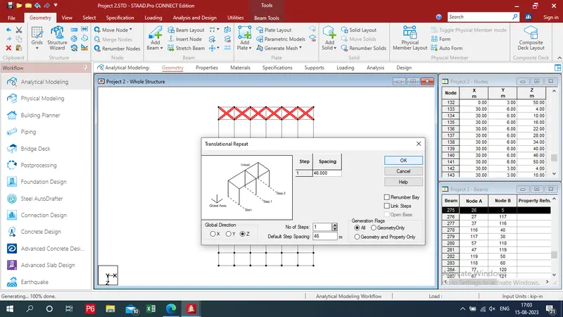
- The structure is created
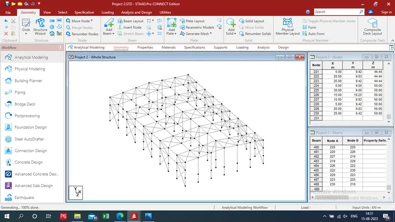 .
.
Step 2: To Apply Properties:
a) Add properties
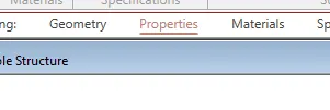
- Click on properties tab which is 2nd stage
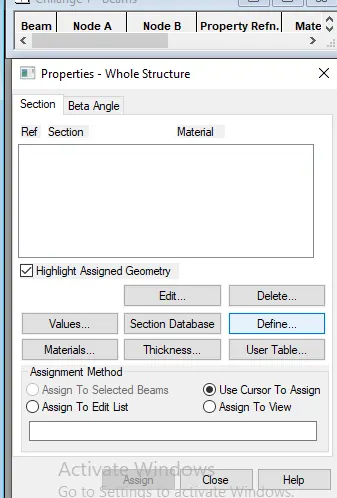
- Click on define
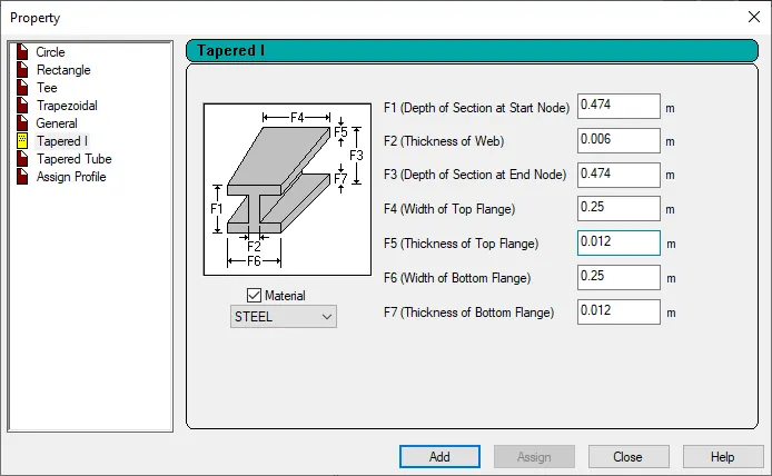
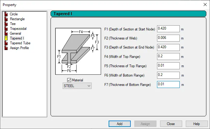
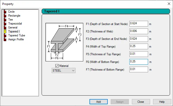
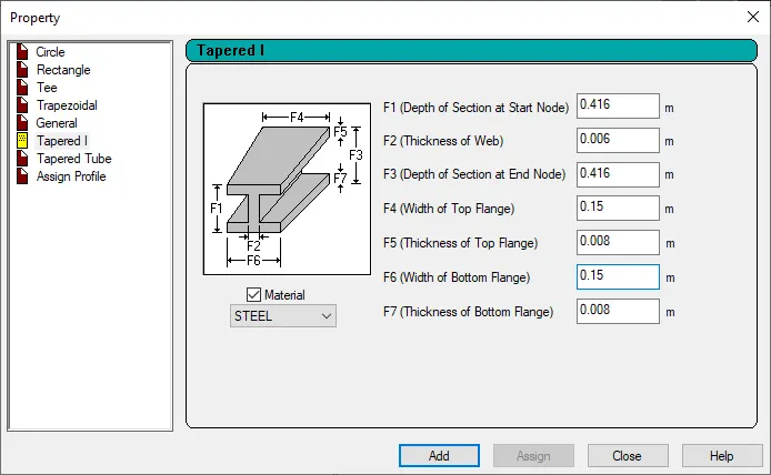
- Select I sectioon and provide its depth and breadth, thickness Then click on add - my beam size is:
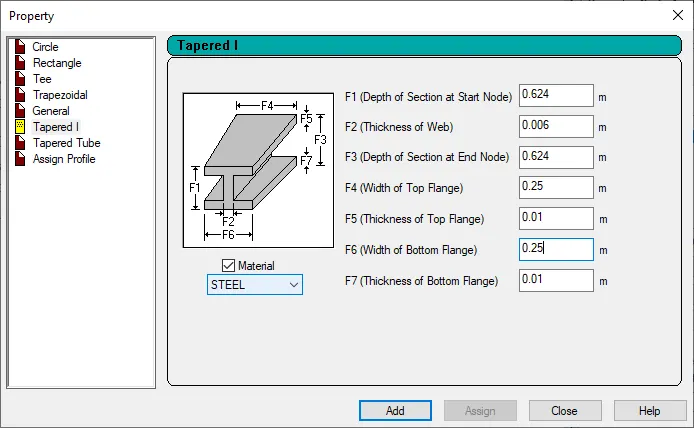
For main Column
For middle Column
For gable Column
For main Rafter
For gable Rafter
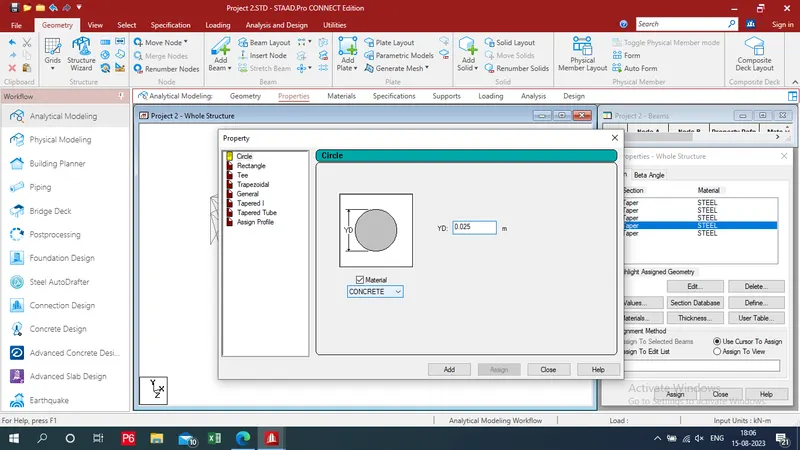
For Bracing
- Then click on section data base - select coldformed steel - choose indiancold form - again click on zee with lips - provide 150ZS60X2
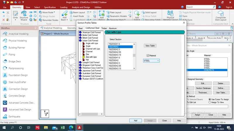
For purlin
b) Assign properties:
- Go to select tab - click on parallel from beam section - select "TO X + CTRL + TO Z"
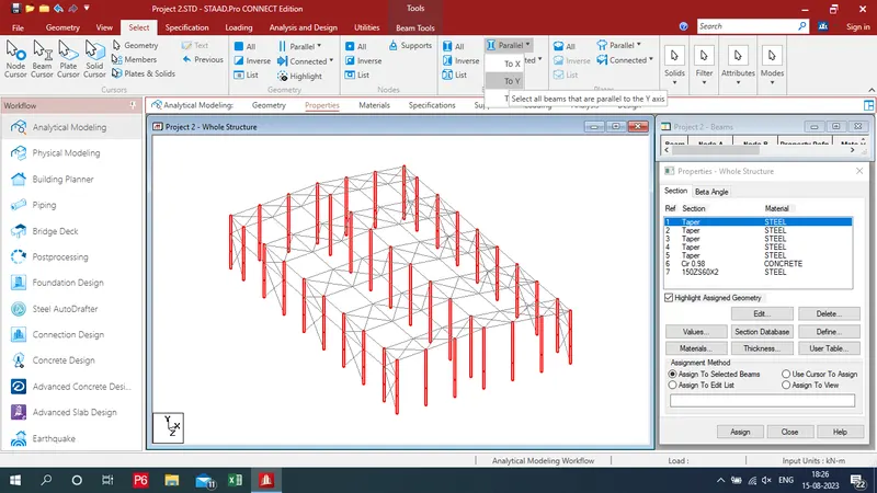
- Go to view tab - selected view
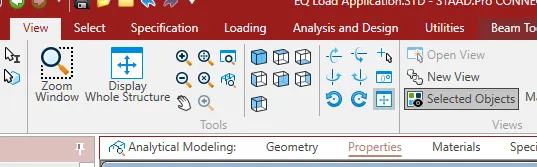
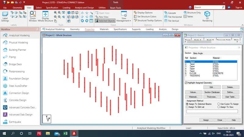
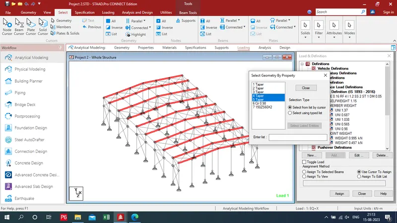
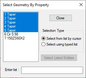
- Click on 1 Taper - Select outer column - Assign to selected beams - assign
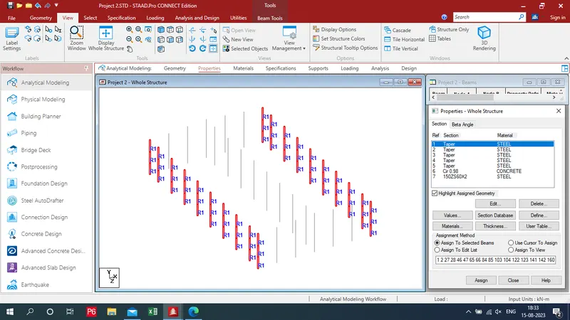
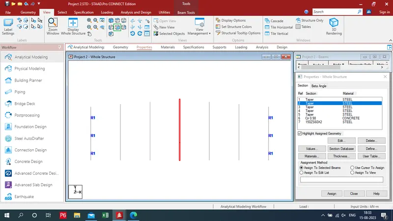
- Click on 2 Taper - Select middle column - Assign to selected beams - assign
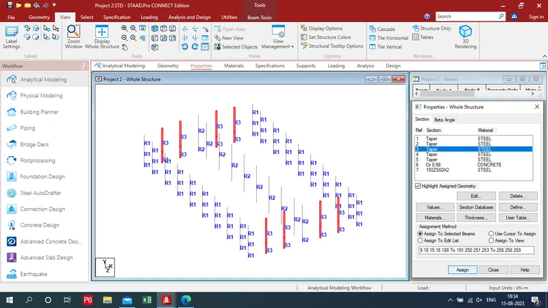
- Click on 3 Taper - Select wind column - Assign to selected beams - assign
- Click on 4 Taper - Select rafter from front view
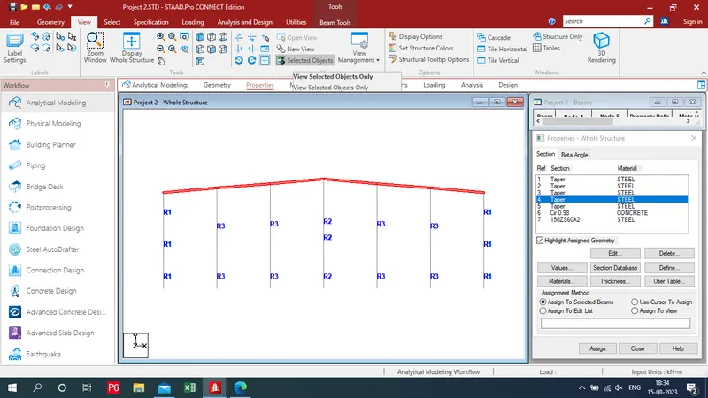
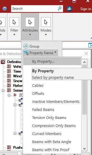
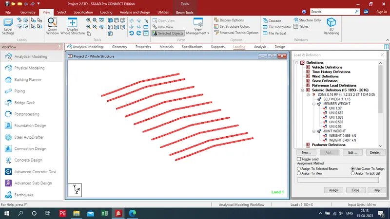
- Unselect braacing - selected objects from view tab
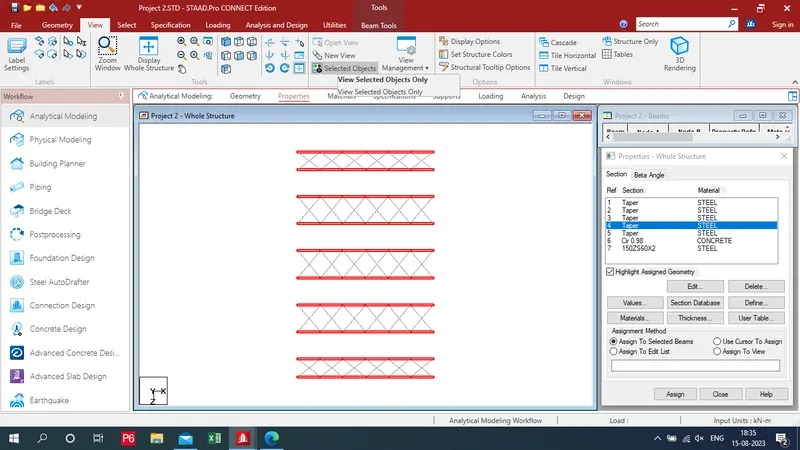
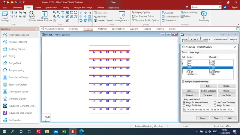
- Click on 4 Taper - Select main rafter - Assign to selected beams - assign
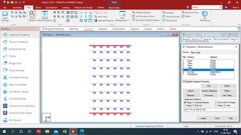
- Click on 5 Taper - Select gable rafter - Assign to selected beams - assign
- Click on 7 section - Select purlin by using Prallel to Z from select - Assign to selected beams - assign
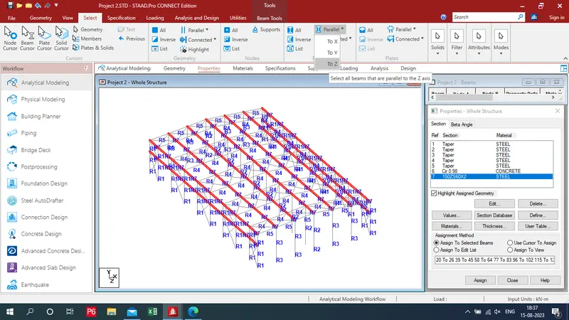
- Click on 6 section - Select Attribute - clcik on missing property - Assign to selected beams - assign
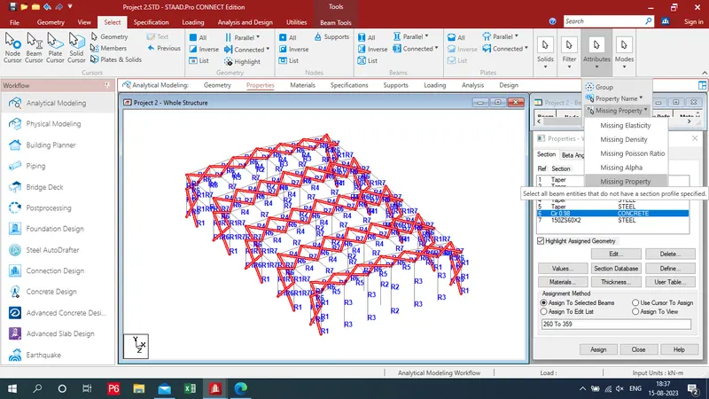
- Assign all properties to wear house building.
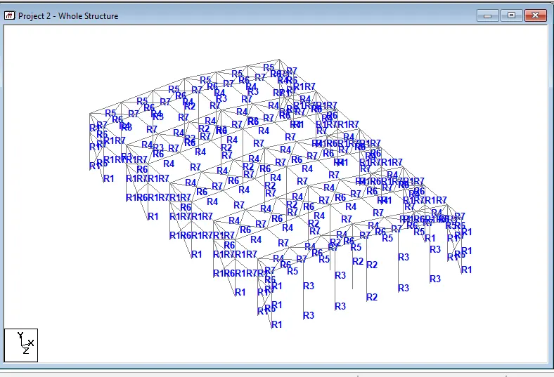
c) Change orientation of wind column
- Then select all wind column - Create beta angle - provide angle as 90 - assign to selected column
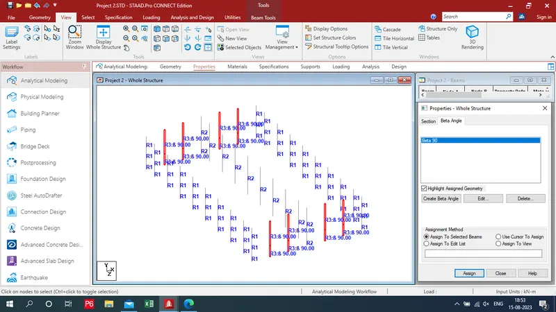
- Orientations is changed of wind column
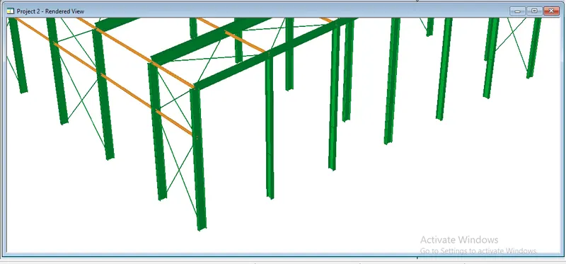
Step 4: To Apply material:
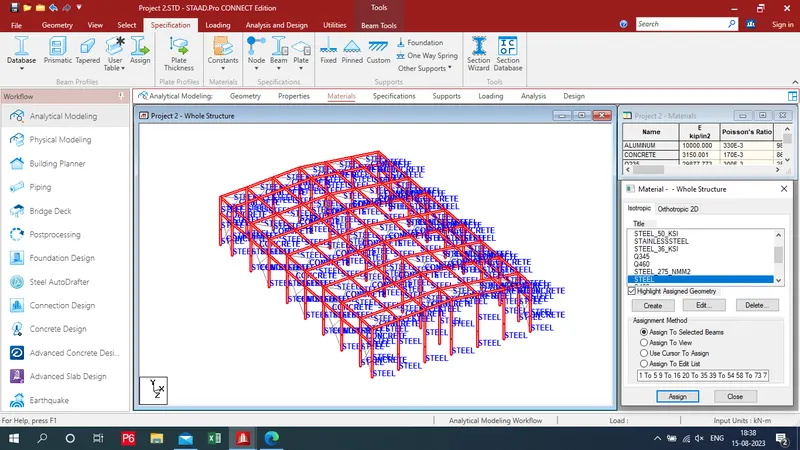
- Go to material tab - select steel - Assign to view - assign - yes
- Material is assign to beam
Step 5: Provide member specification:
- Click on beam
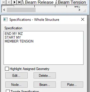
- Provide released My and Mz moment at end of beam - add
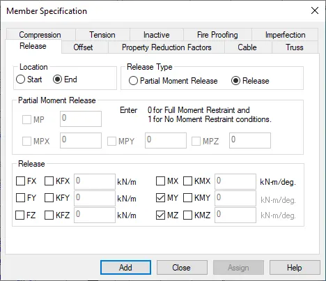
- At start only relesed My - add
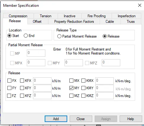
- Add tension specification
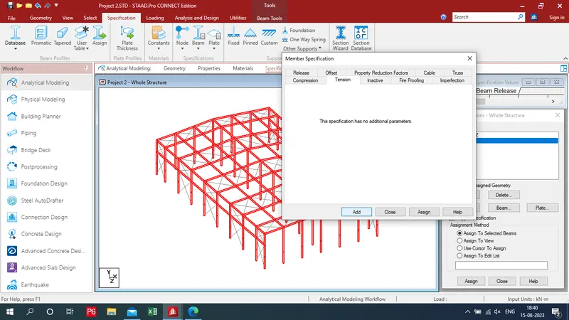
- From properties section select bracing - go specification section
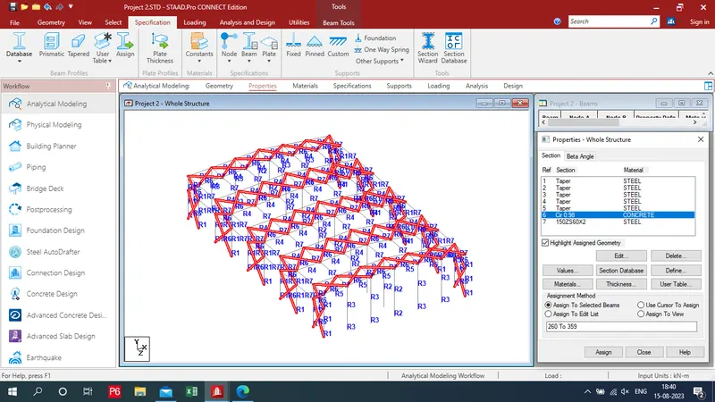
- Assign Member tension specification to it
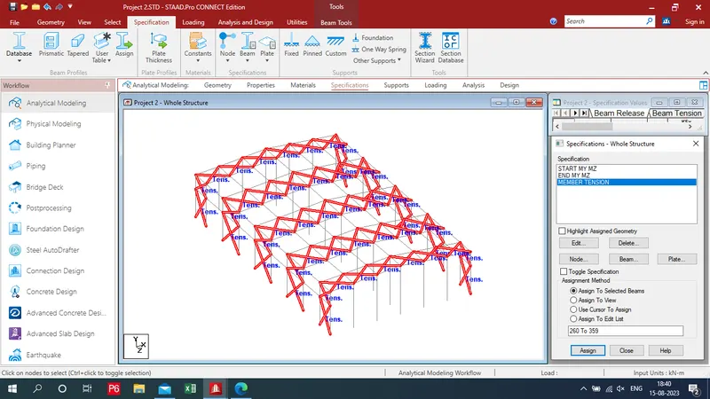
- Click on End My Mz - select wind column - Assign to selected beam - assign - yes
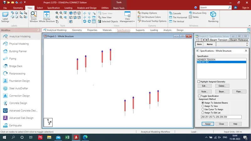
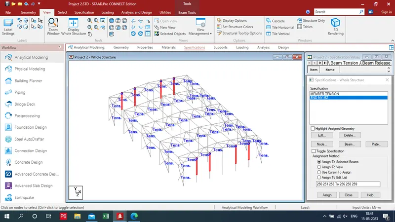
- Select Purlin - Click on End My Mz - select wind column - Assign to selected beam - assign - yes
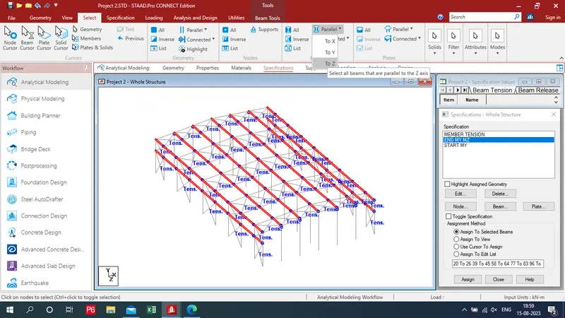
- Again assign Start My to purlin
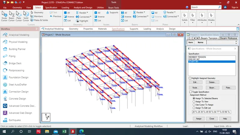
Step 6: To provide Supprots:
- Go to next tab as a Supports Click on create
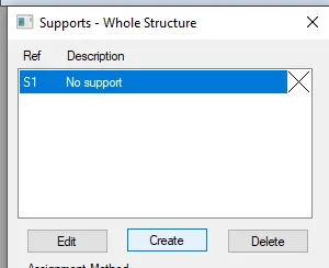
- Provide pinned support - Add - Close
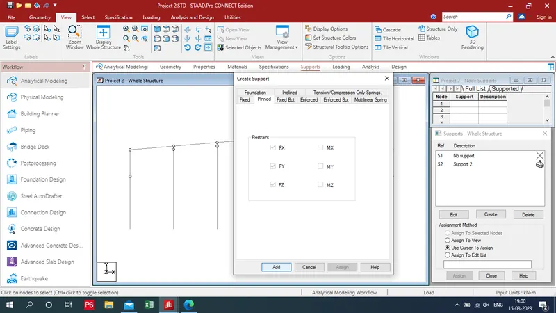
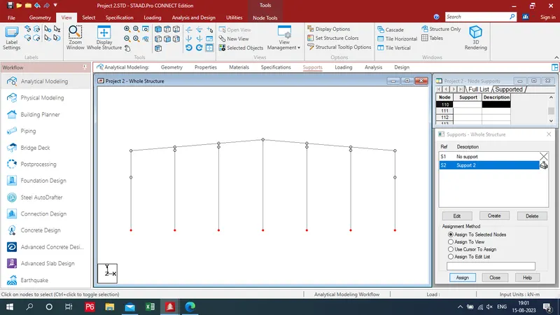
- Go to view tab select front (5th) view
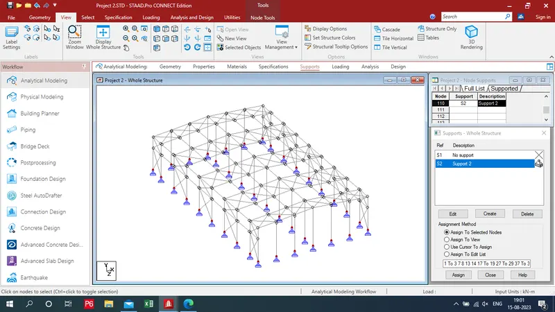
- Then assign them to the drawing by using "use cursor to assign" - select bottom nodes- assign .
- Click on 3D view
Step 7: To Apply Loading:
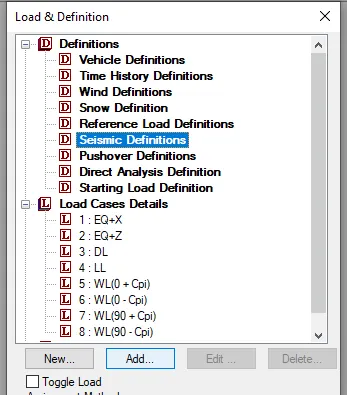
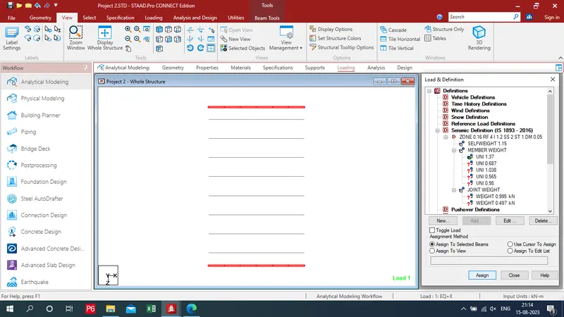
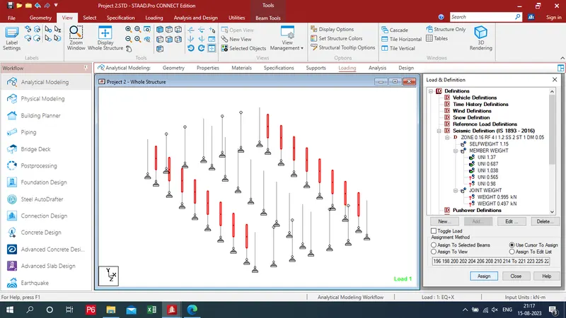
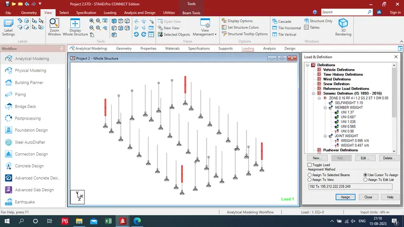
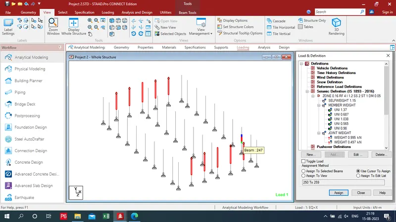
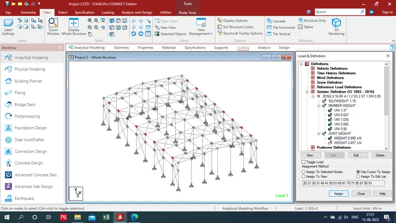
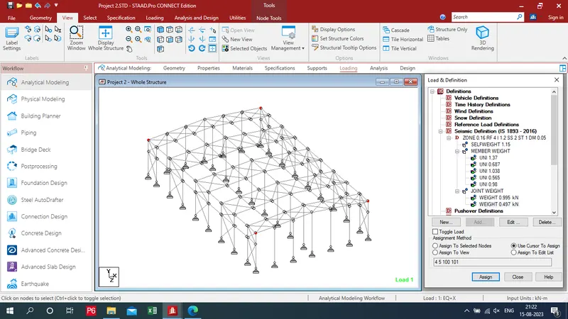
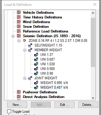
a) Definitions of seismic load4:
- Click on seismic definitions - add
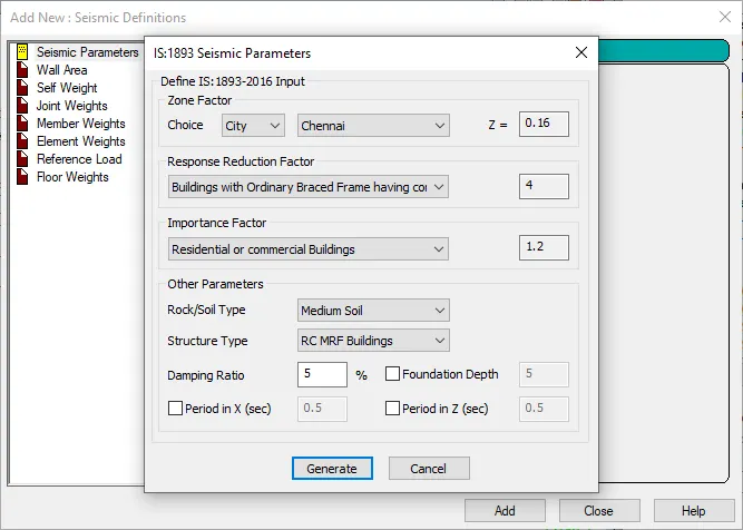
- Select Code - IS 1893-2016 - Click on Generate
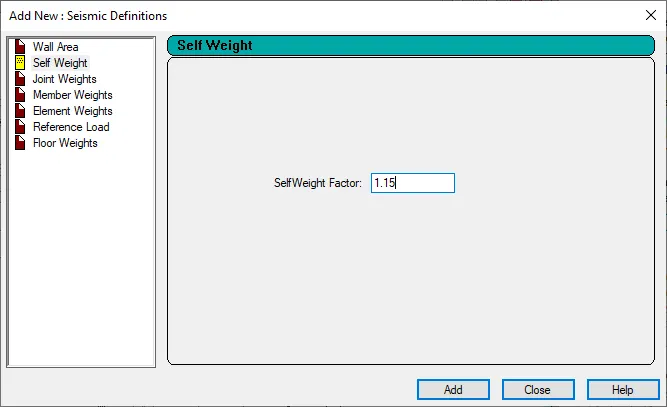
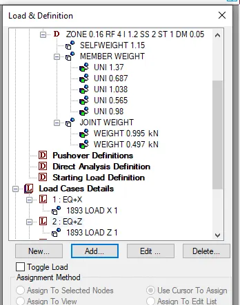
- Provide self weight , Member weight, and joint weight
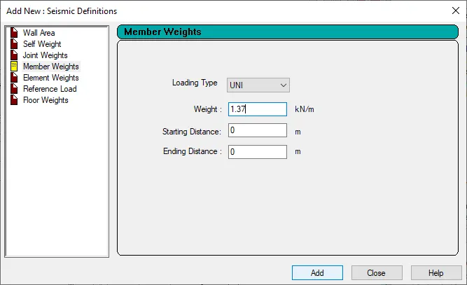
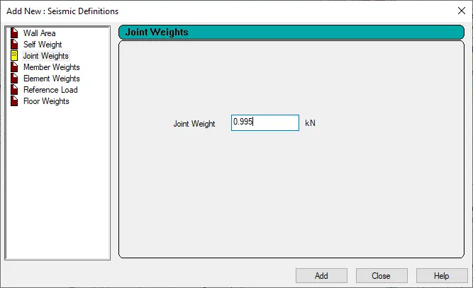
- Add similarly other member weights and joint weights
- assign them aacording to componenet
b) Apply Load Cases Details:
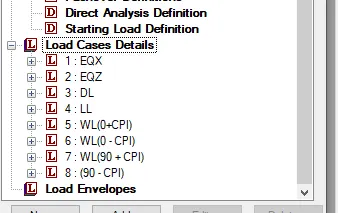
- Go to loading tab select "load cases deatils" - add
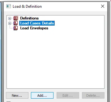
- loading type : select seismic-H - Title : EQX - add - Title : EQ-X - add - again give Title : EQZ - add - Title : EQ-Z - add
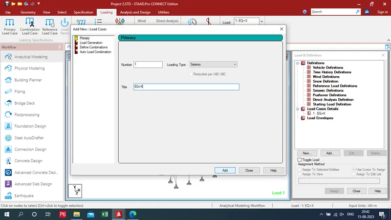
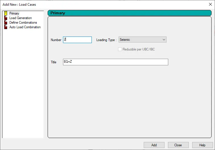
- Provide priamry load cases as DL And LL
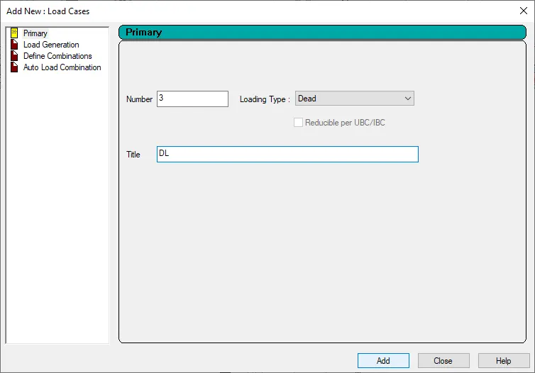
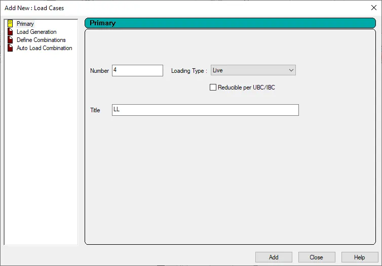
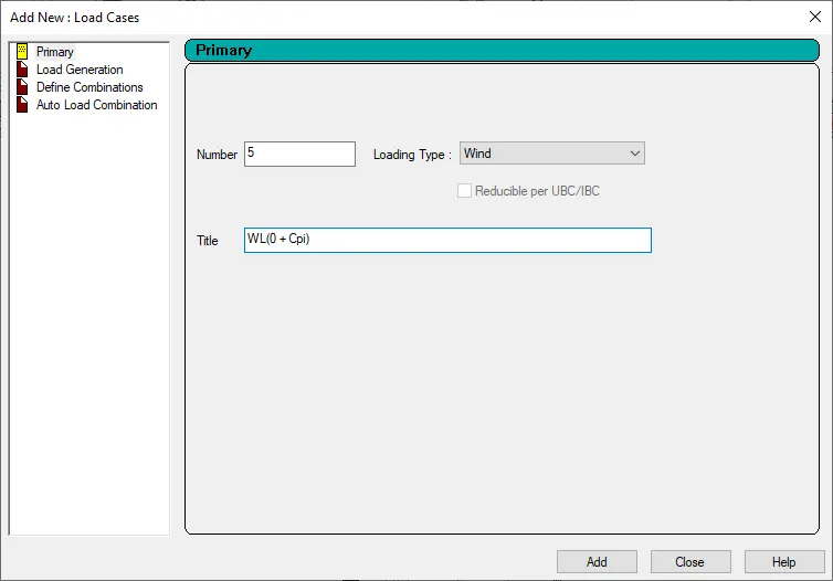
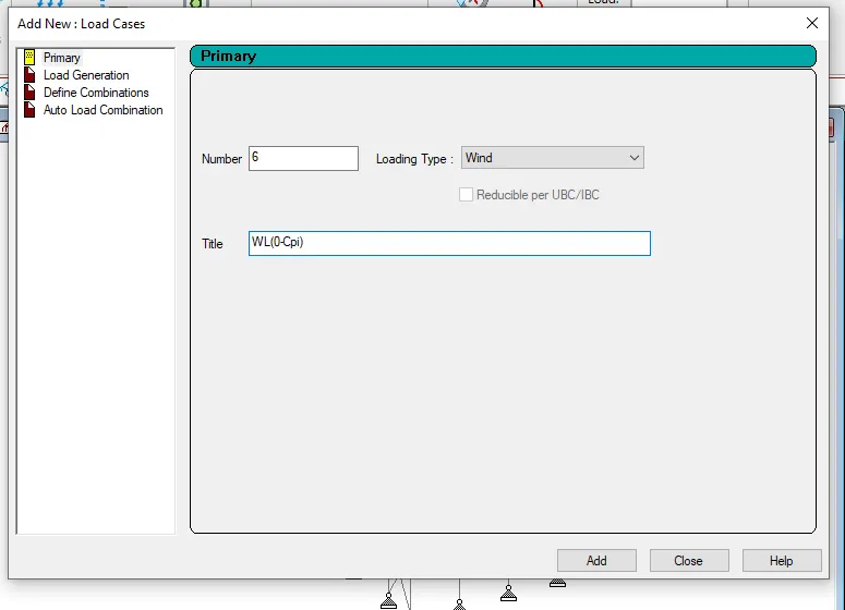
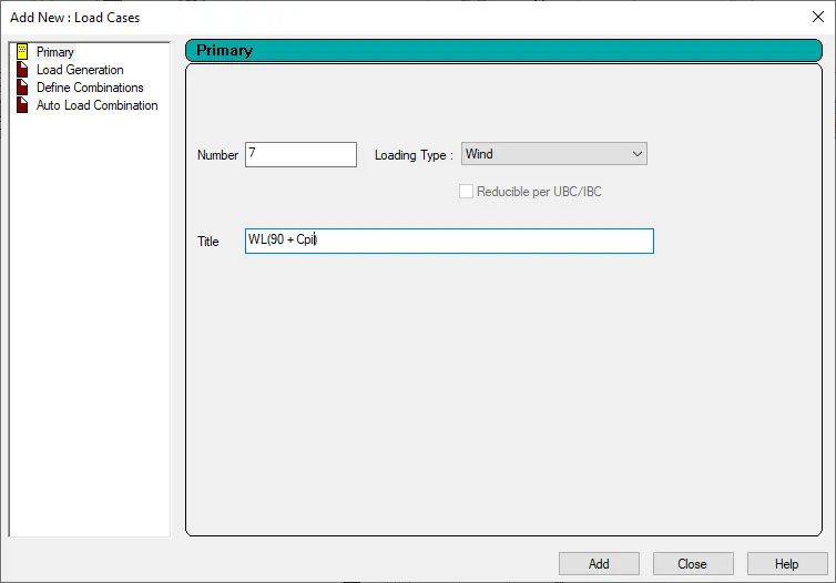
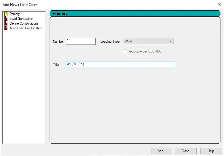
- Thses all loads are add
c) Assign Load Cases Details to structure:
i) Seismic Loads:
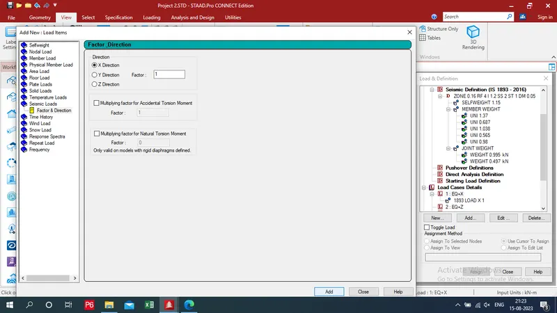
- Select EQ+X - seismic load - Direction:X - Factor: 1 - add
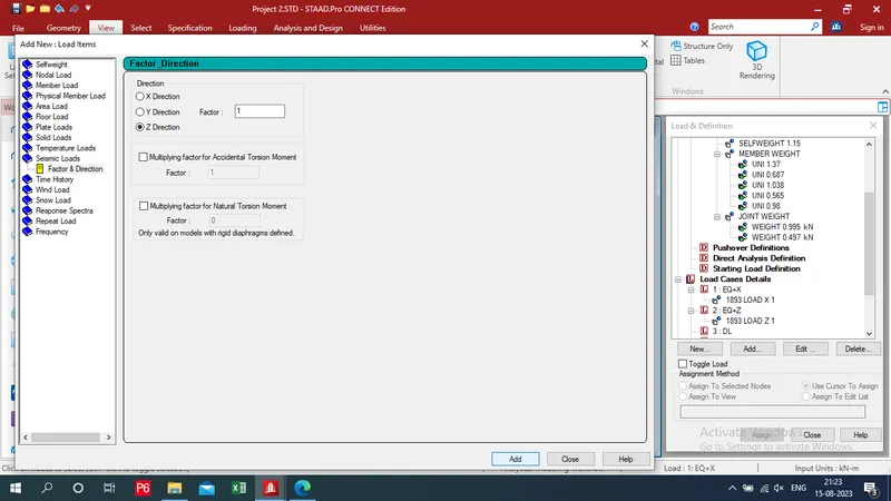
- Select EQ+z - seismic load - Direction:z - Factor: 1 - add
- Assign seismic load factor successfully to building
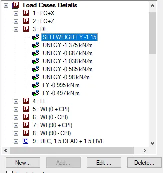
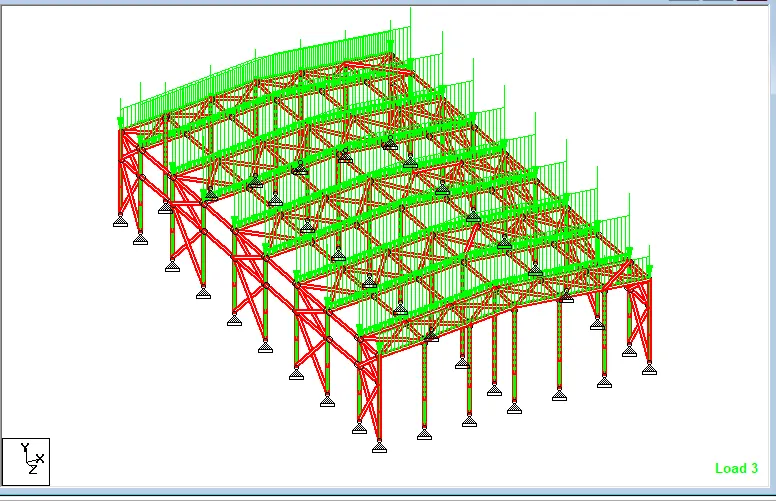
ii) Dead Loads:
- Select DL - Add - Choose Self weight : -1.15 - Add
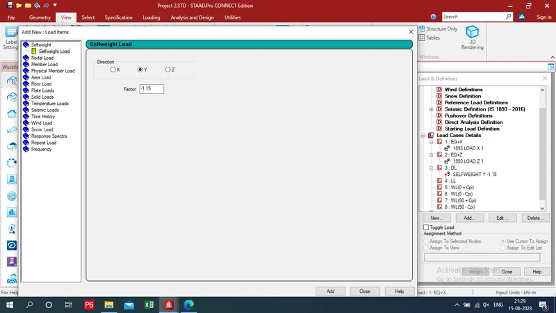
- Assign to view - assign - Yes
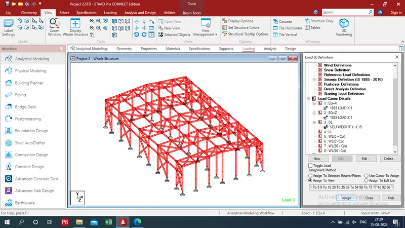
- Again select DL - add - member load - w1: -1.375 - add
- Select Rafter - Assign it to main rafter
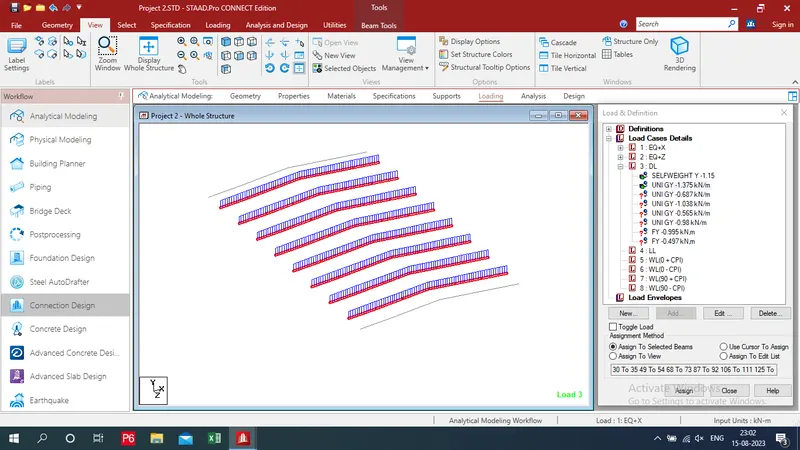
- Repeat this process for gable rafter
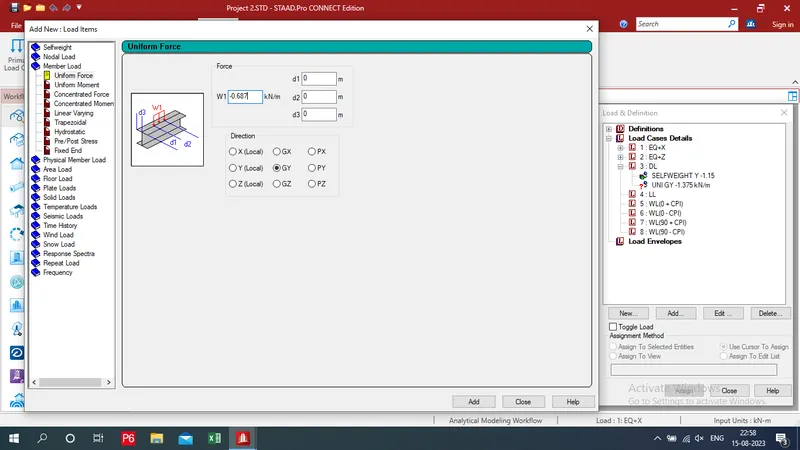
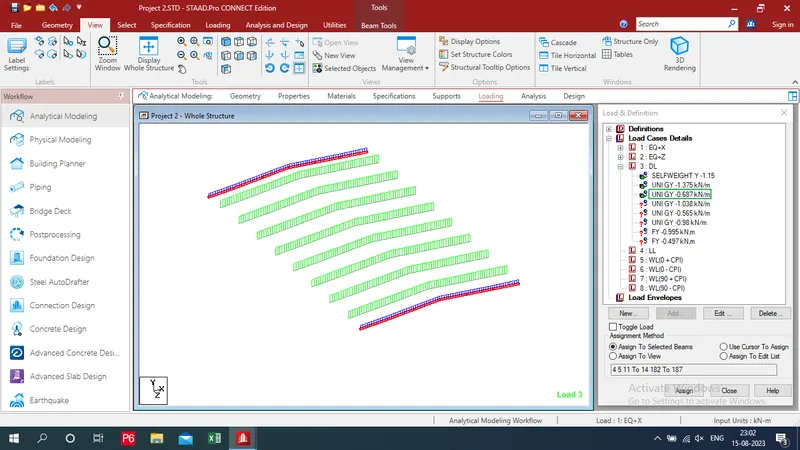
- Add again load for column and assign them by using assign method of assign to selected beam
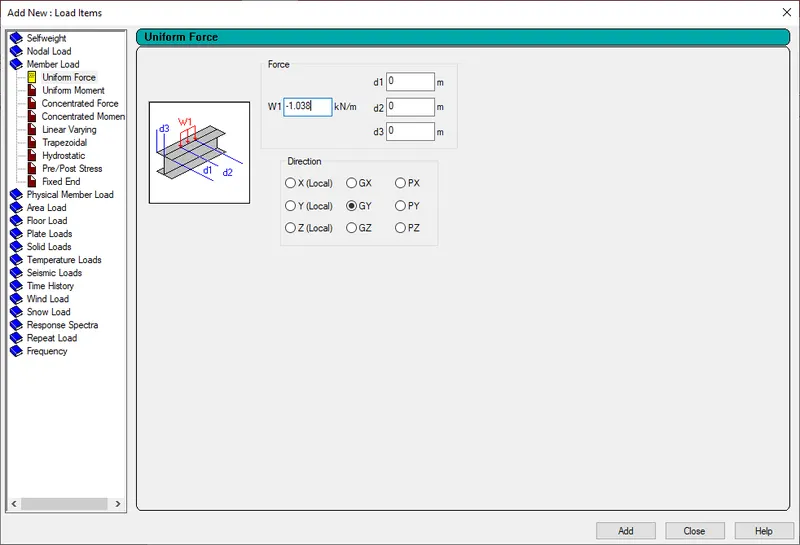
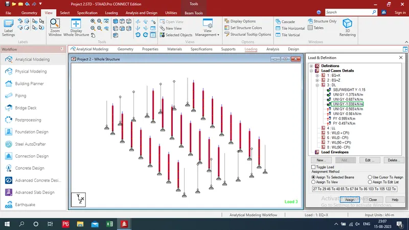
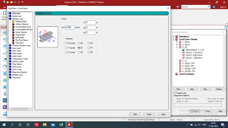
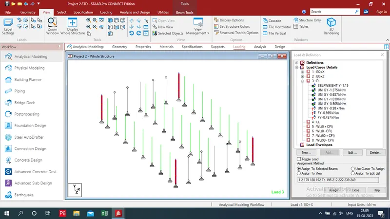
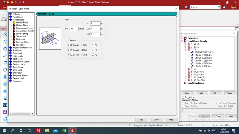
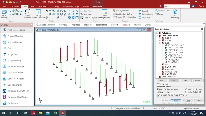
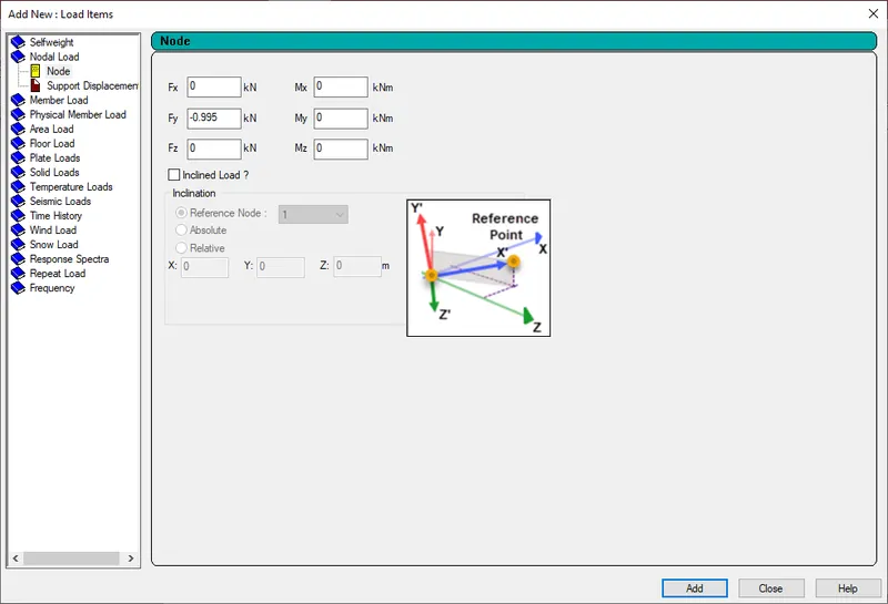
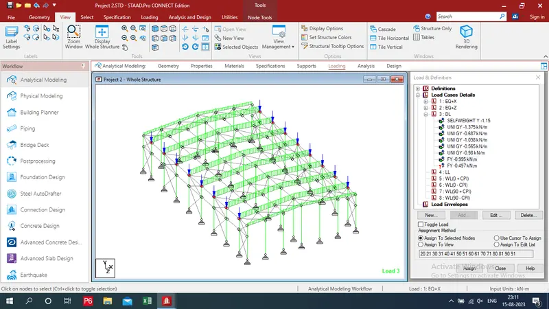
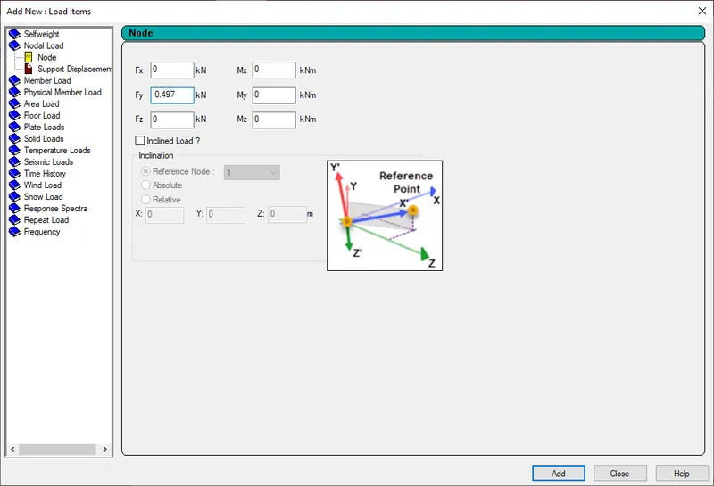
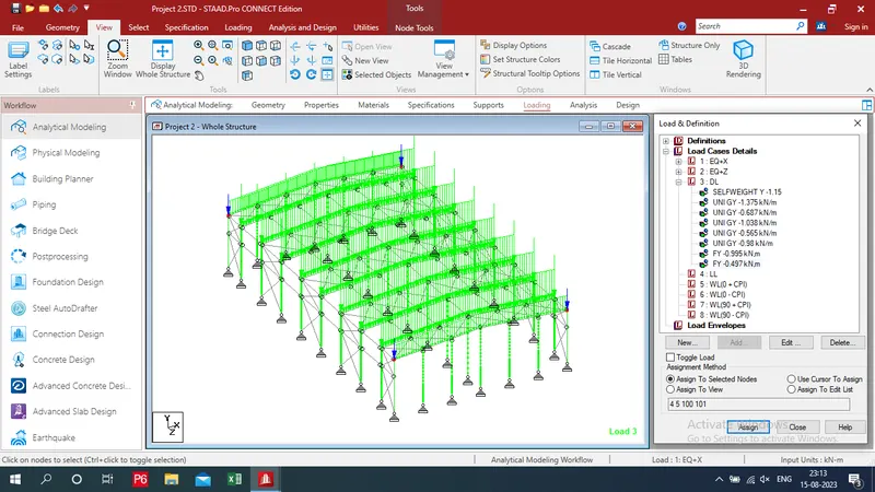
- Assign all dead loads
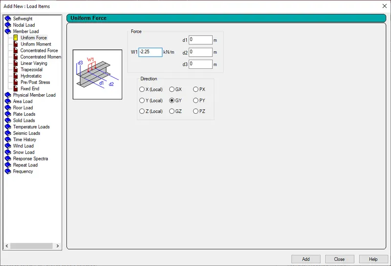
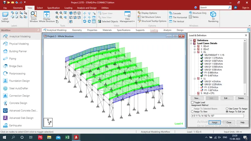
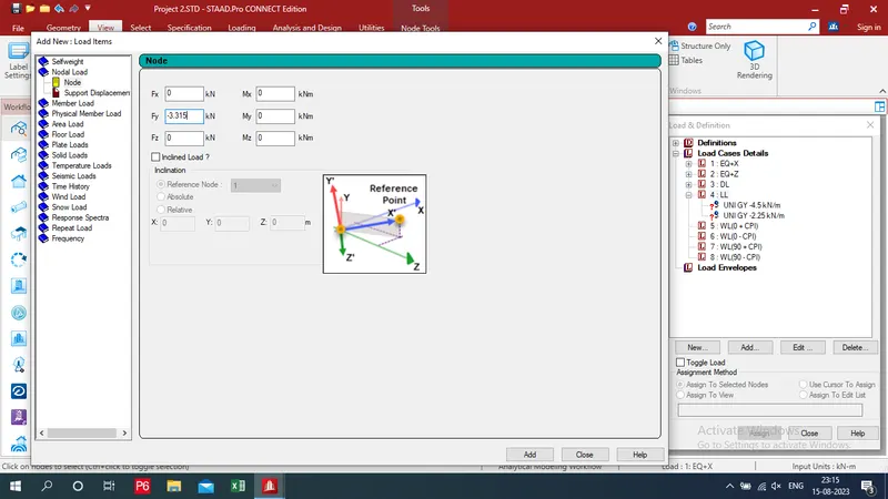
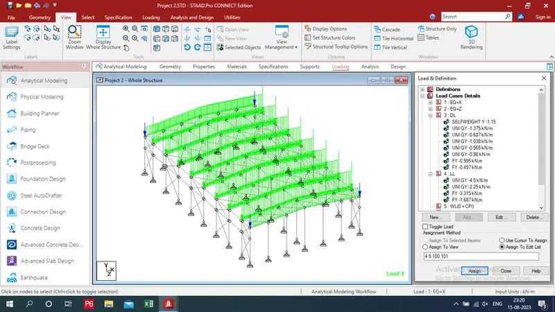
iii) Live Loads:
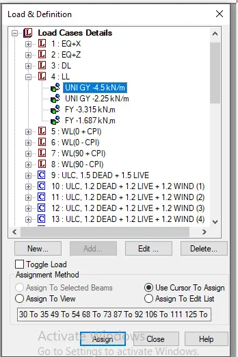
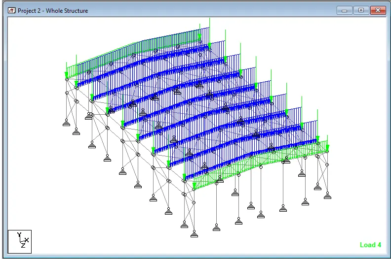
- Now select LL - add member load and noadal load
- According to direction select its direction - and assign them by using - assign to edit list
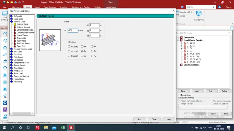
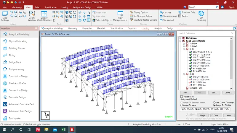
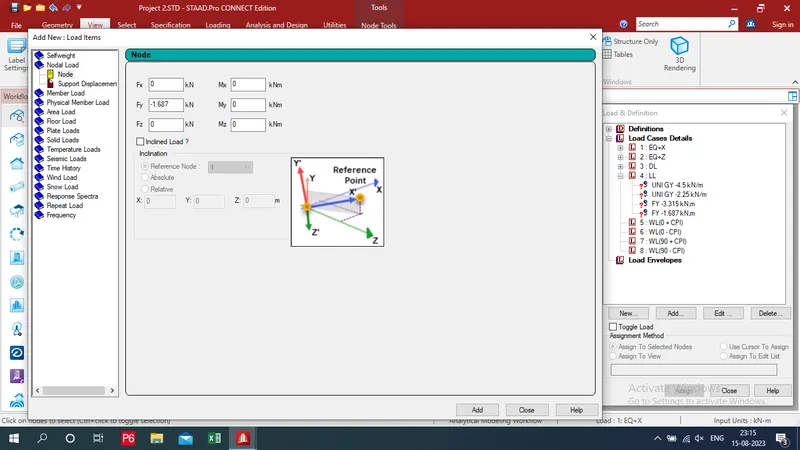
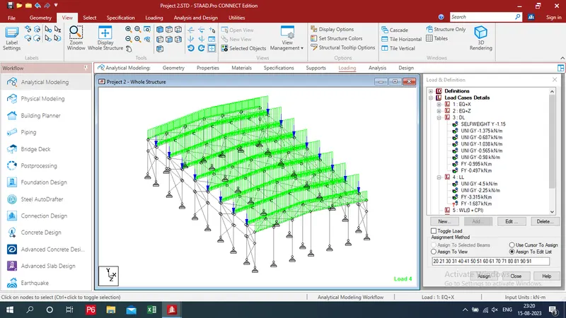
- Assign all live loads
iv) Wind Loads:
A) WL(0+Cpi)
- Again add wind loads and asssign them according to component
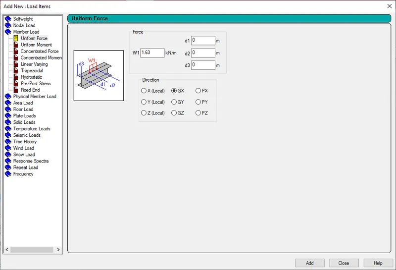
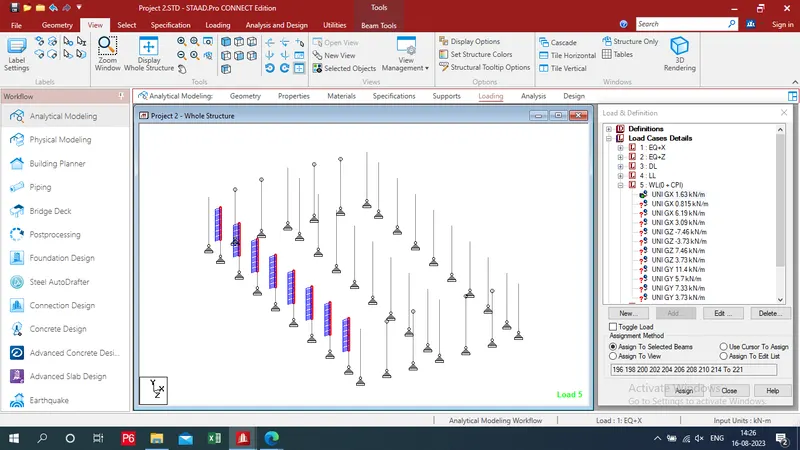
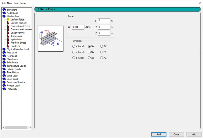
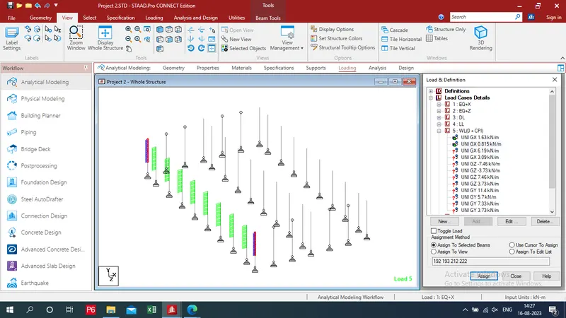
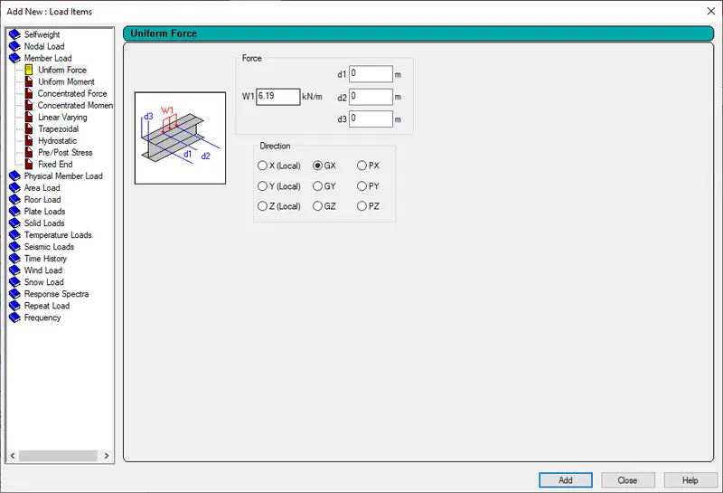
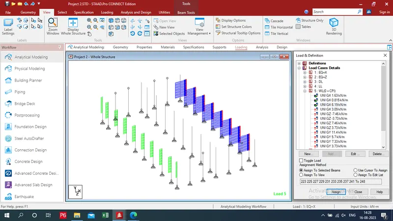
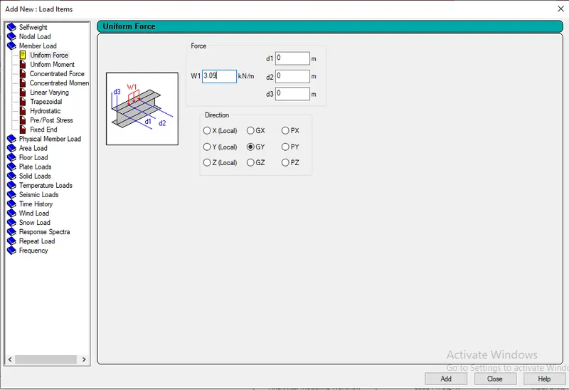
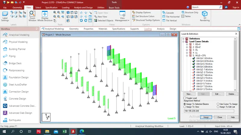
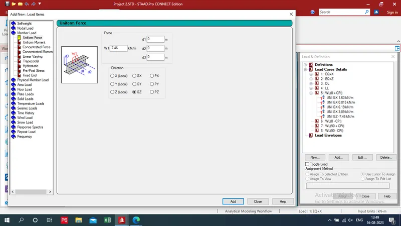
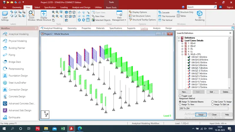
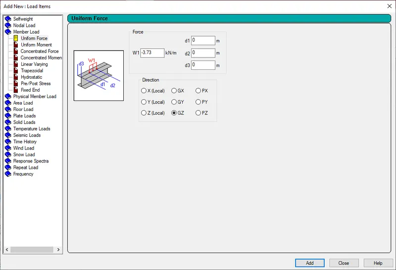
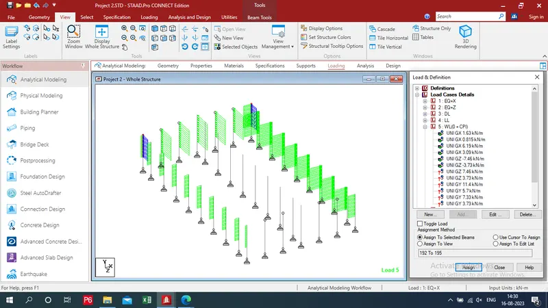
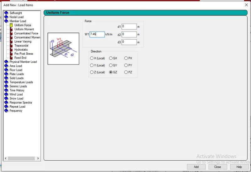
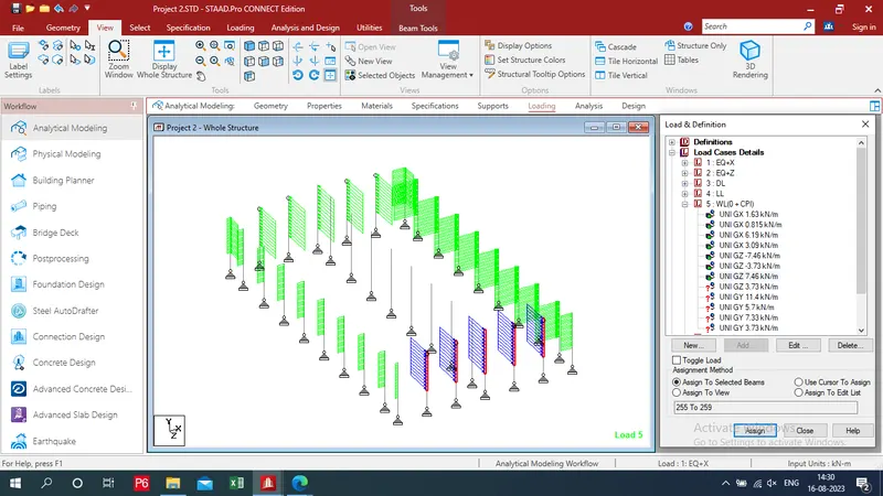
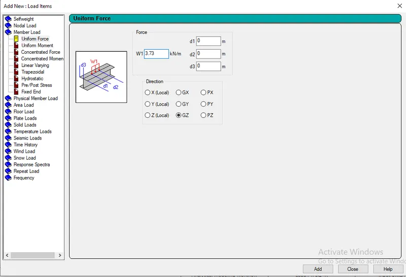
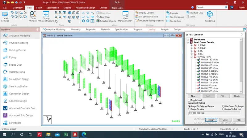
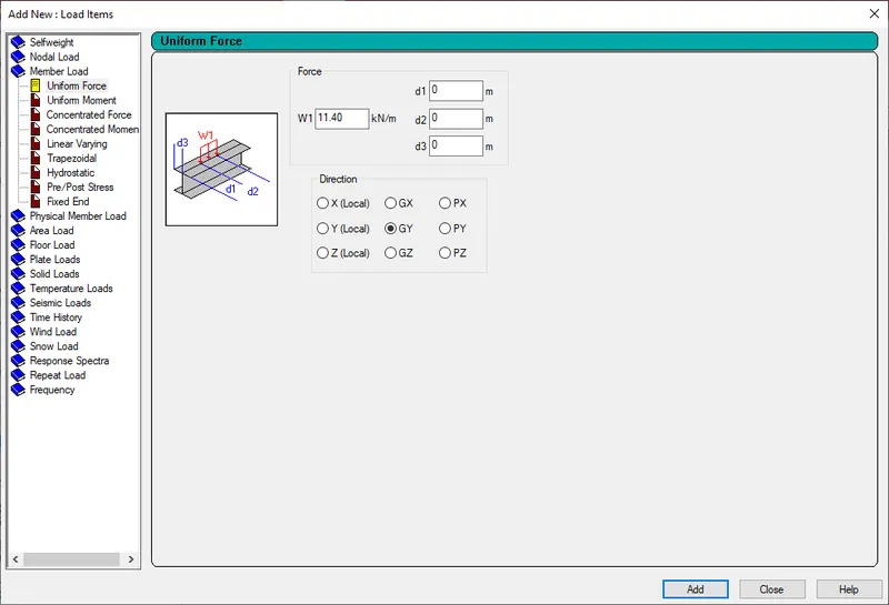
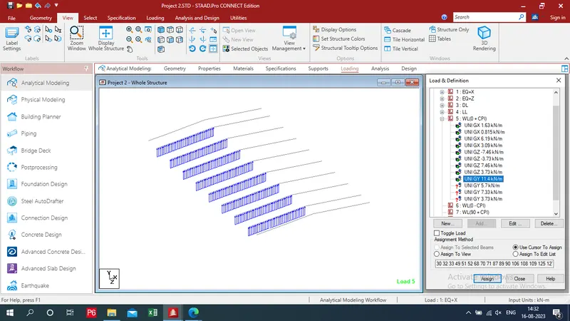
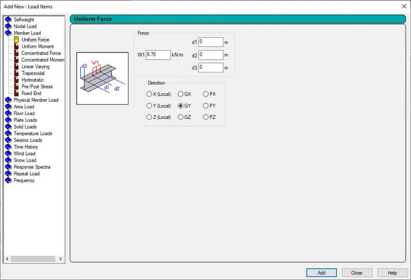
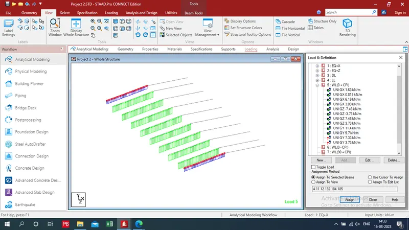
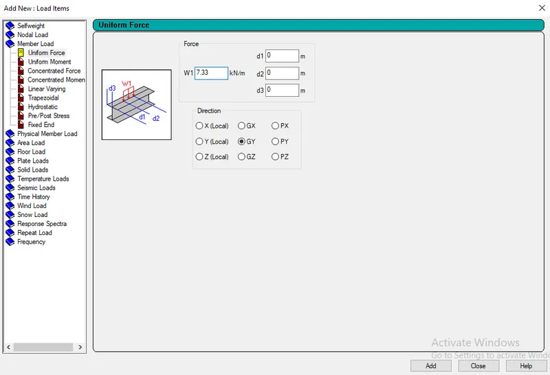
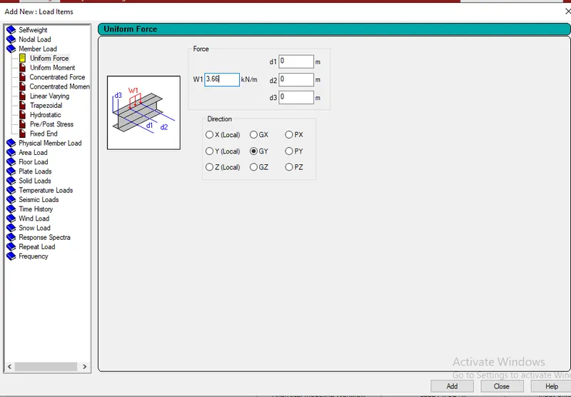
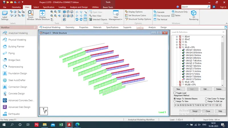
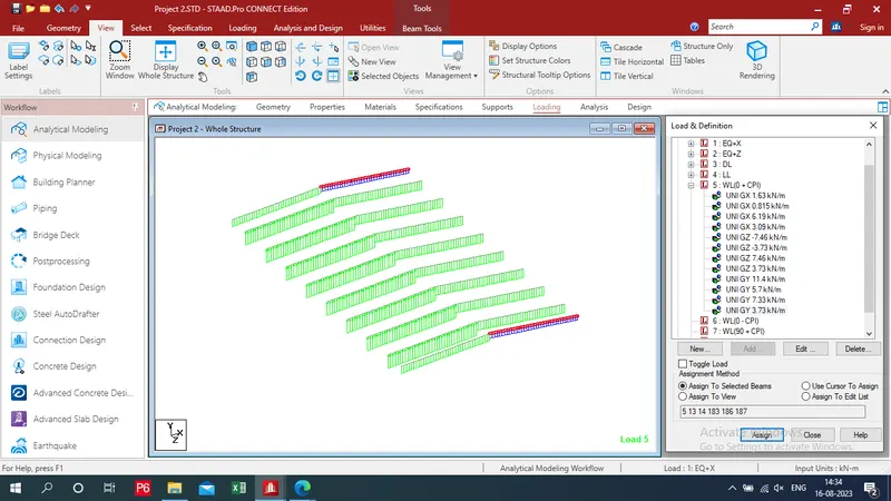
- Assign all WL (0 - Cpi)
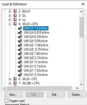
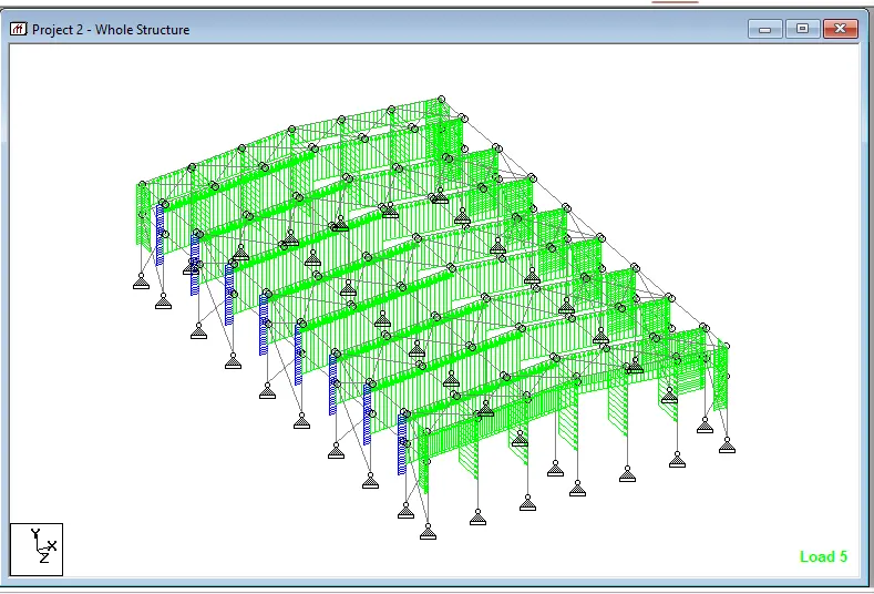
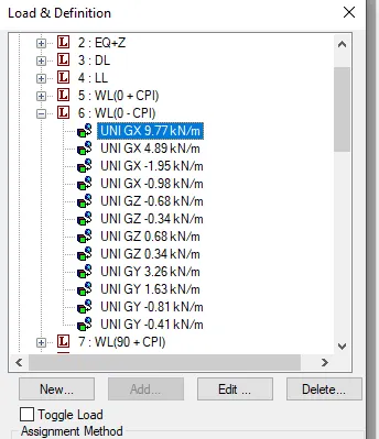
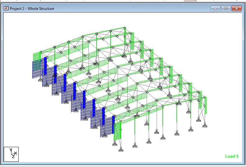
B) WL(0-Cpi)
- Assign all WL (0 + Cpi) by using assign to edit list
- Select uni GX 1.63 - Click on assign to edit list - Press "Ctrl + A" for selecting all nodes - Press "Ctrl + C" for copy all nodes
- Then select GX 9.77 - Press "Ctrl + v" for paste all nodes - assign - yes
- Repeat this process for all loads
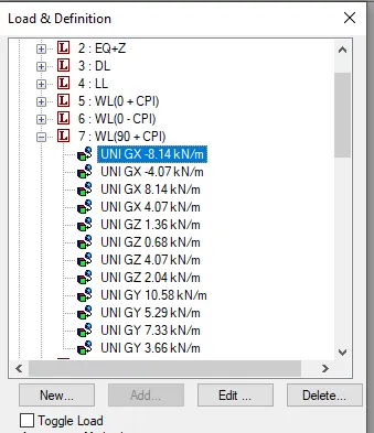
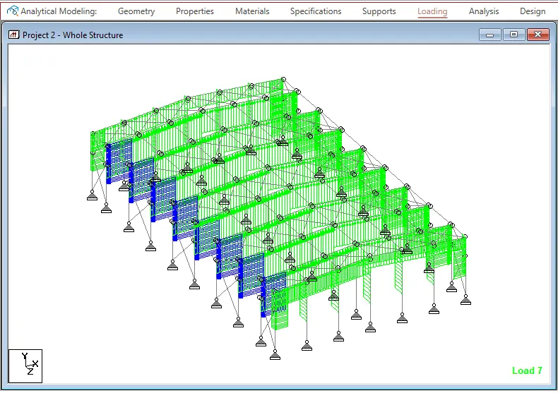
C) WL(90+Cpi)
- Assign all WL (0 + Cpi) by using assign to edit list
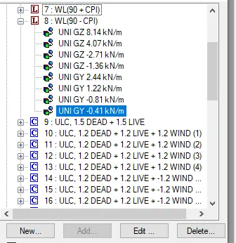
D) WL(90-Cpi)
- Assign all WL (0 + Cpi) by using assign to edit list

d) Apply load combination:
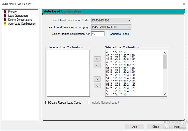
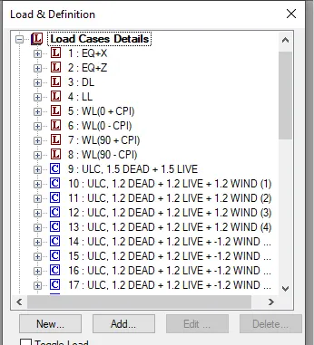
- Select Load cases deatail - click on auto load combination
- chooses load combination caod: IS456/800 - select load combination category - Click on generate load -add
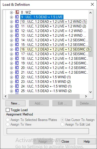
- Assign all loads to building
Step 8: Provide analysis:
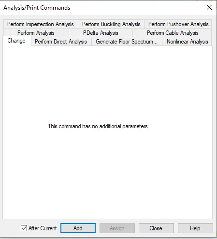
- After going to analysis tab "Define command" - select perform analysis - add - close
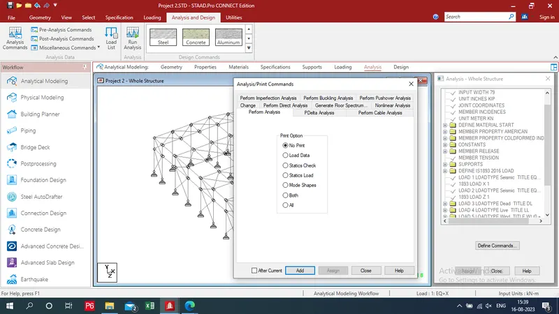
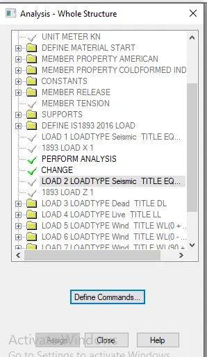
- Then select LOAD 2 LOADTYPE seismic - Click on Define command - Click on Perform analysis - check box After current - add
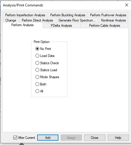
- Click on Change - add - Close
- Repeat this process after selecting LOAD 3 LOADTYPE Dead
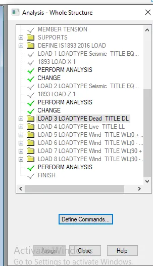
Step 9: Define parameters :
a) Choose code type:
- Select material as steel
- Click on IS 800 2007 LSD
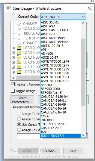
b) Assign Paramters:
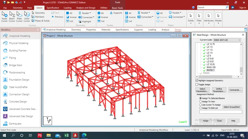
- Now click on Define Paramters
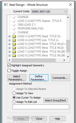
- Provide different paramters
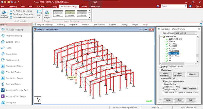
- Click on BEAM - Check box of (1) - Add
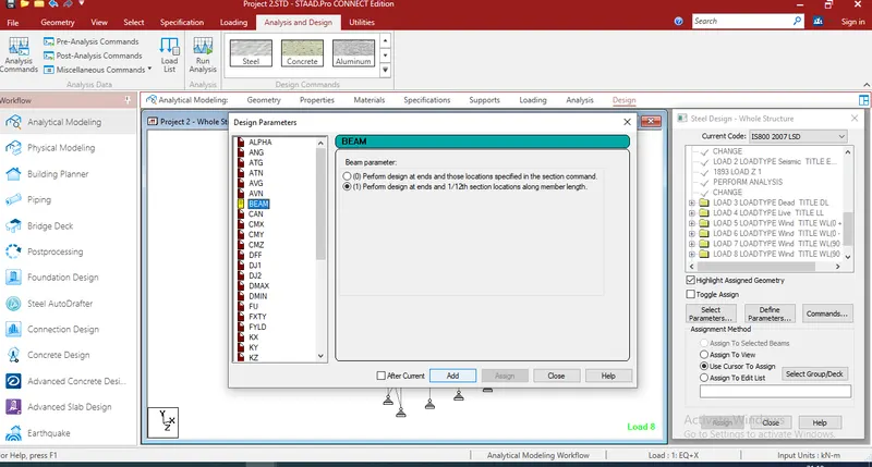
- It is aasign to view - assign
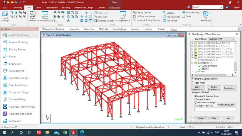
- Add FU and assign them according to componenet
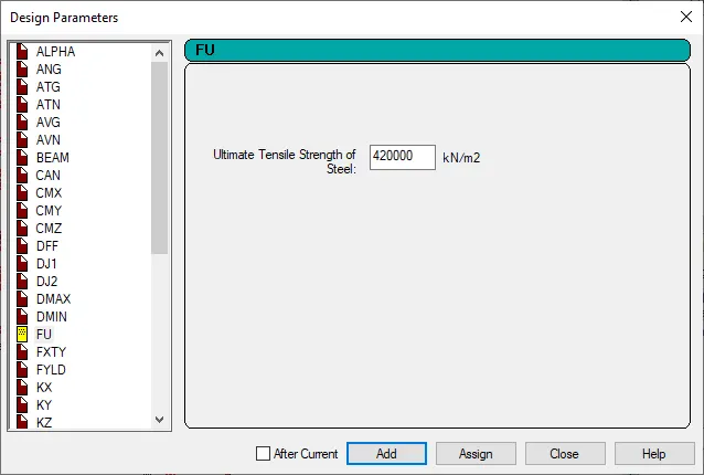
- Select Bracing
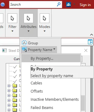
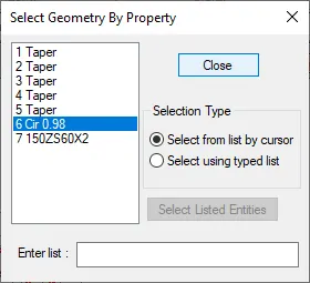
- Assign paramters to barcing
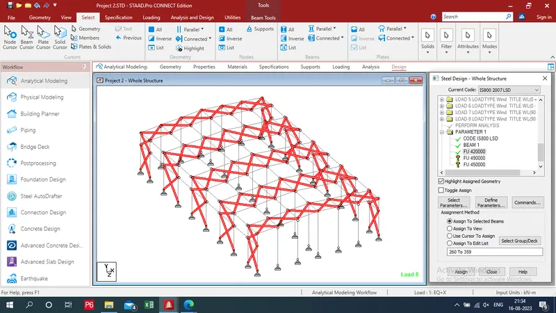
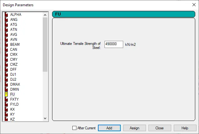
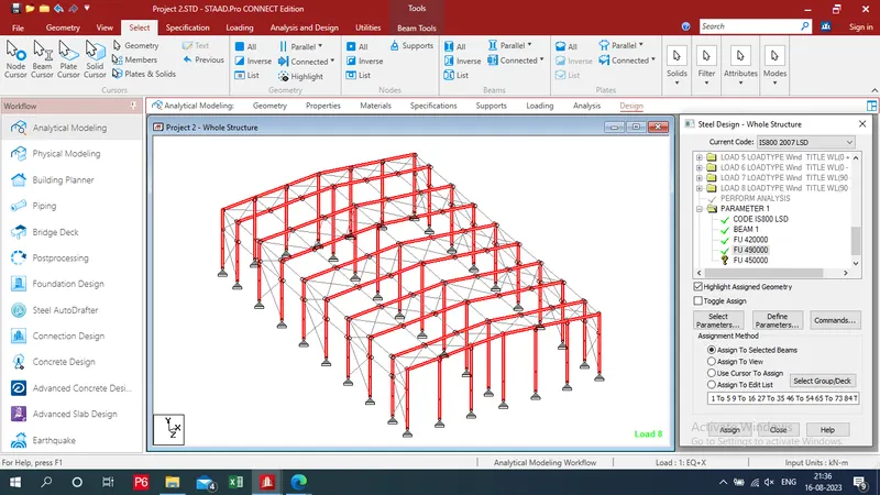
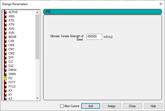
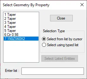
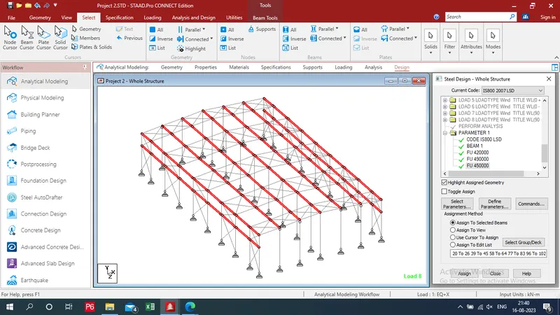
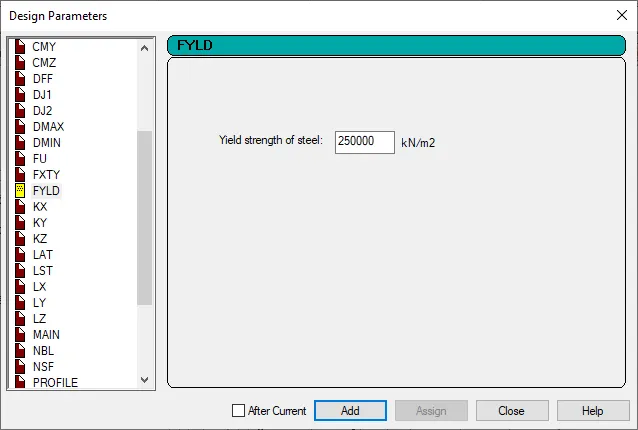
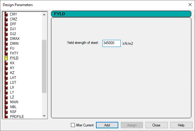
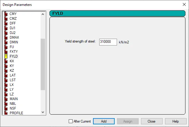
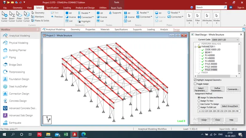
- Add FYLD - assign it by using assign to edit list
- Select paramters of FU and then select FYLD parameters and assign the paramters of FYLD
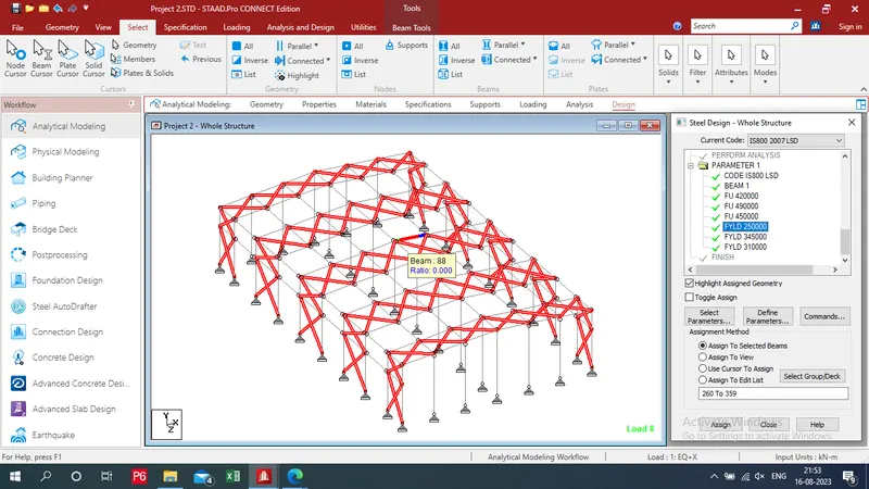
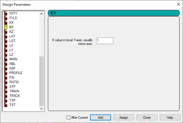
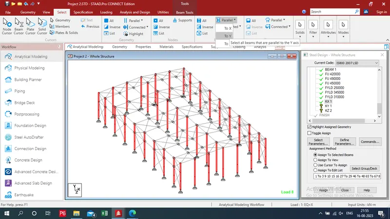
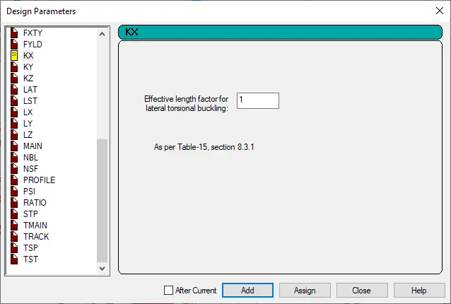
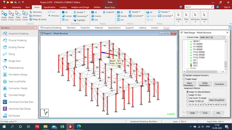
- Add KX , KY and KZ
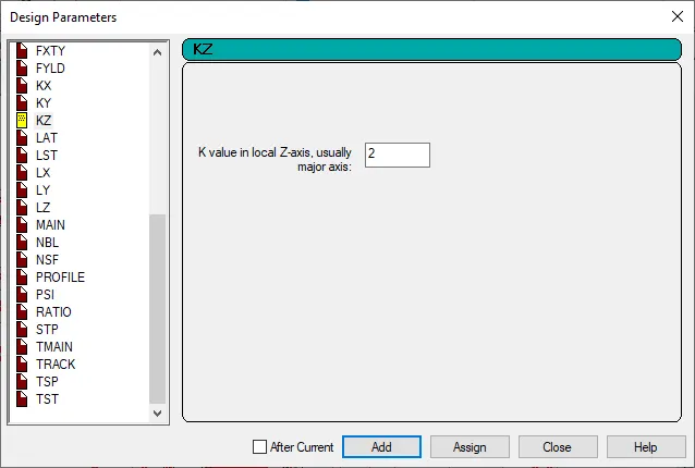
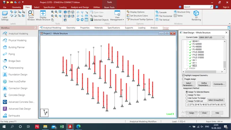
- Add LX, LY and LZ for Rafter
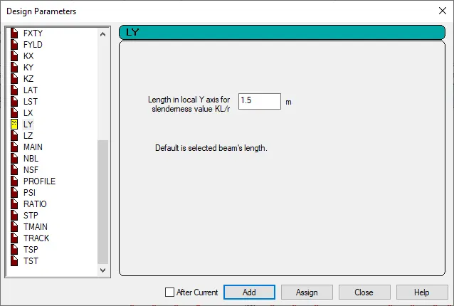
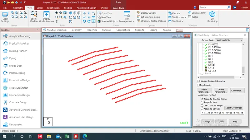
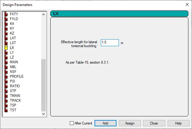
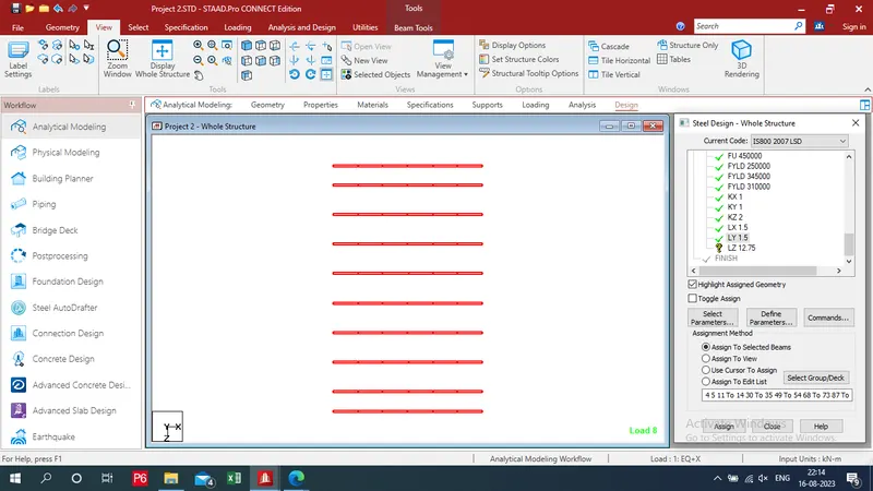
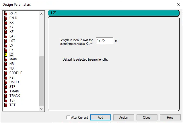
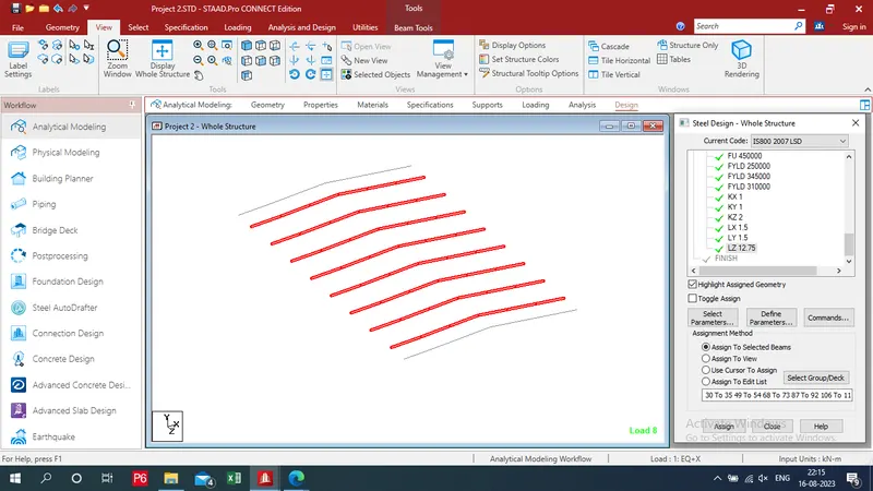
- Add LX, LY and LZ for column
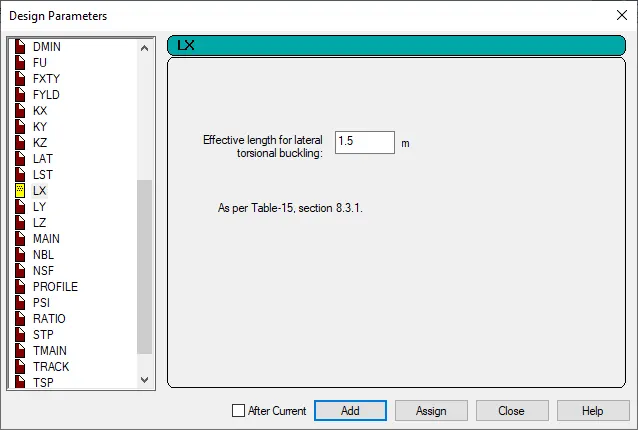
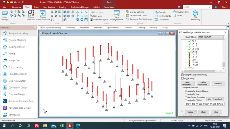
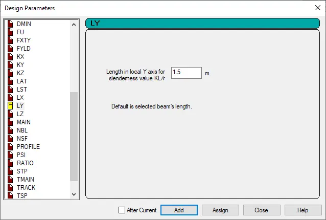
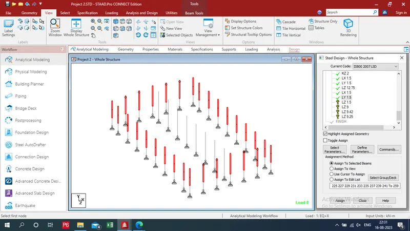
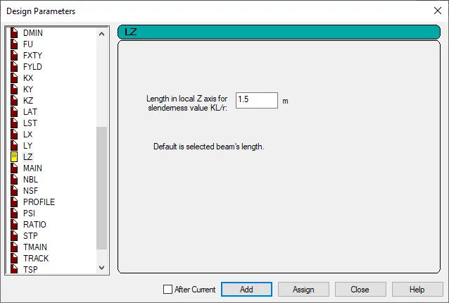
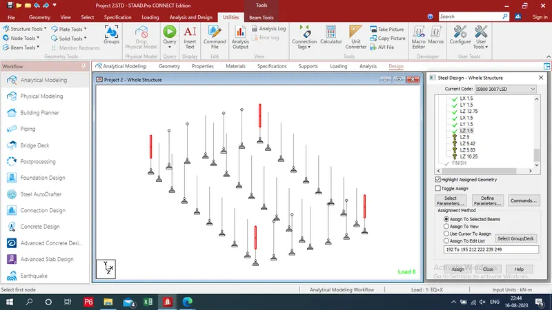
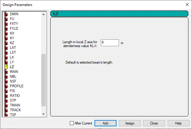
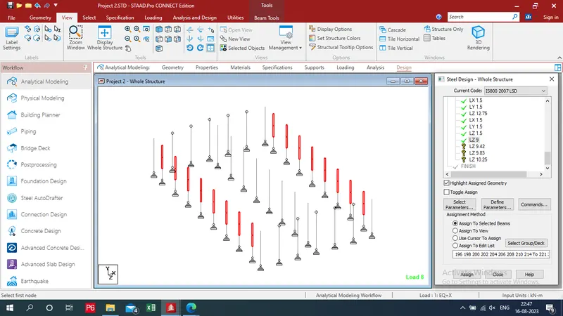
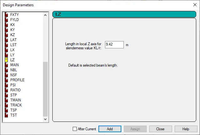
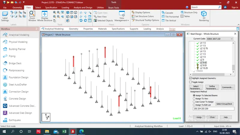
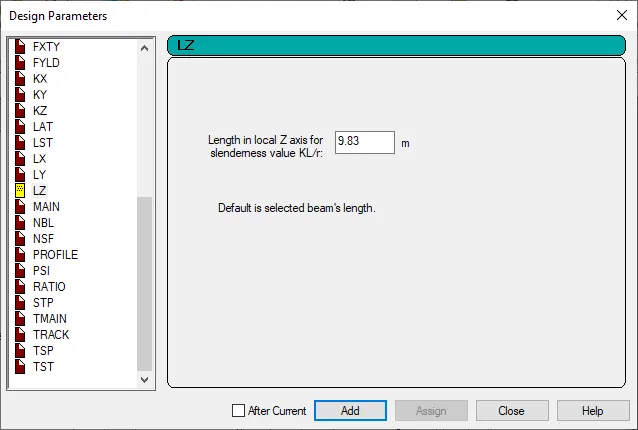
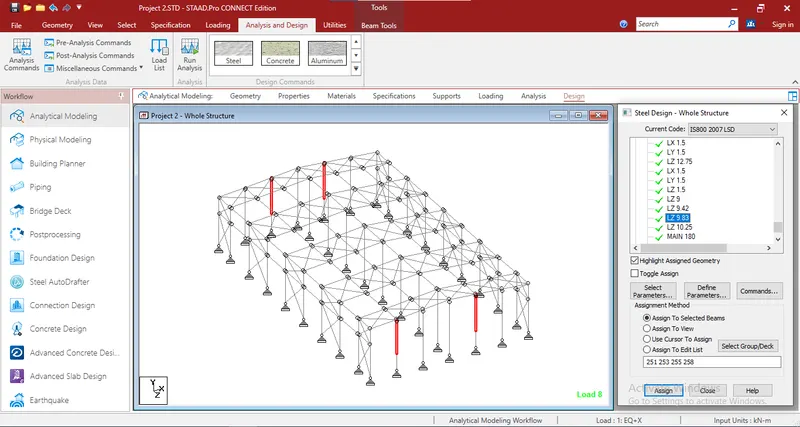
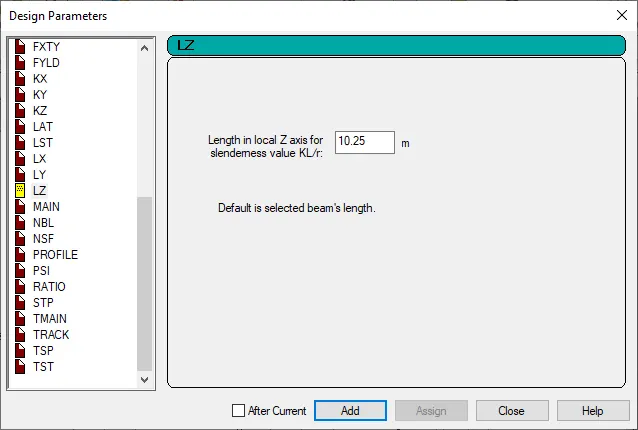
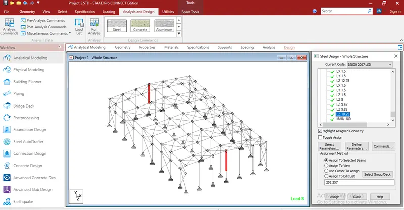
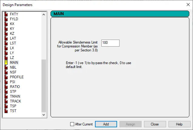
- Add MAIN
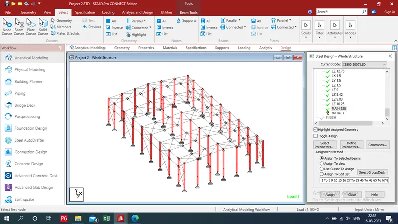
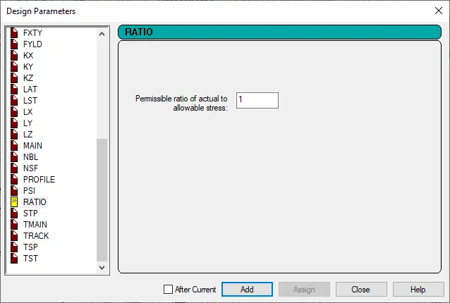
- Add Ratio
 .
.
Step 9: Run analysis:
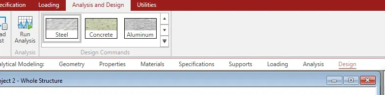
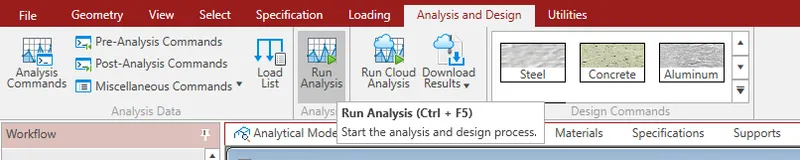
- Run analysis from analysis and design tab
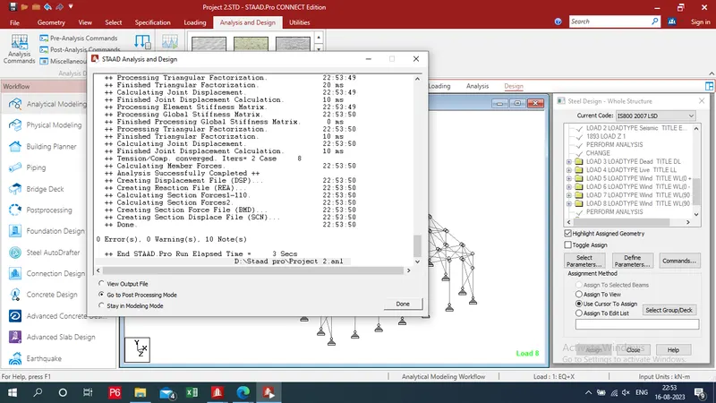
- Click on Go to post processing mode - Done
- Select loads - > - Apply - Ok
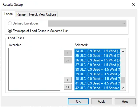
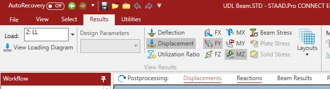
- Click on displacement, MZ we get BMD and click on FY we get sfd
Skeletan structure
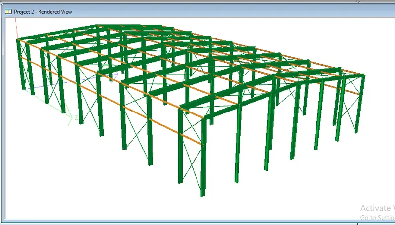
3D Structure
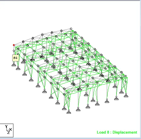
Dispalecment
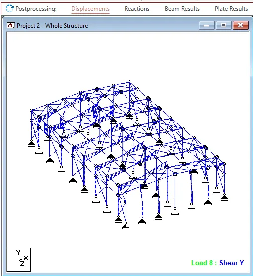
SFD @ y axis
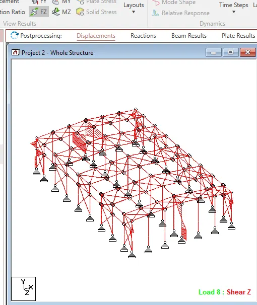
SFD @ Z axis
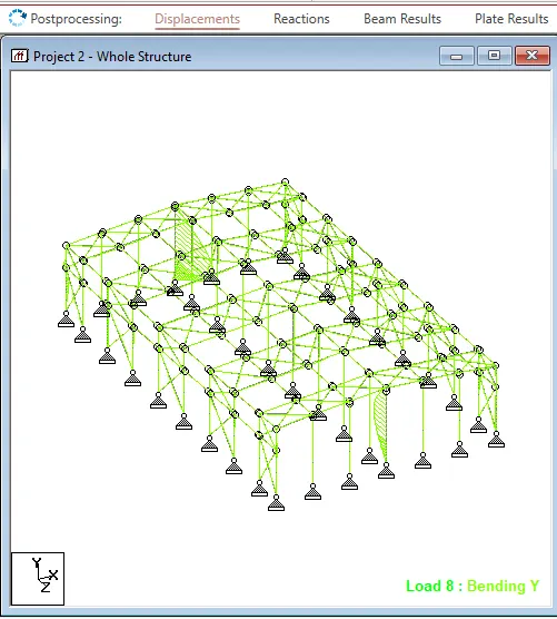
BMD @ Y axis
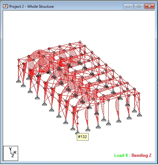
BMD @ Z axis
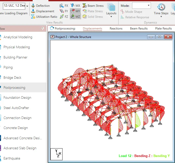
BMD for load combination
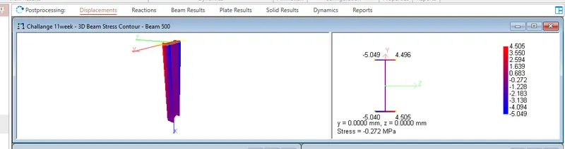
Stress in column
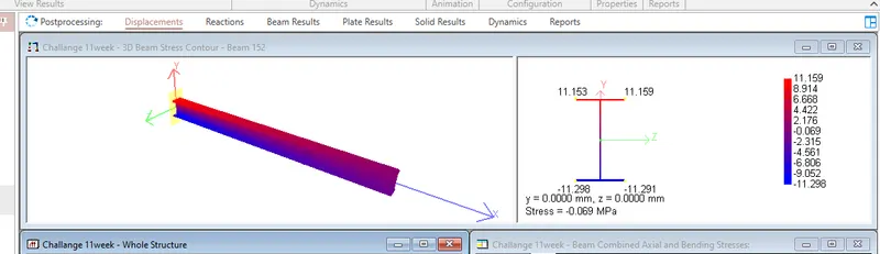
stress in beam
4) Design Report:
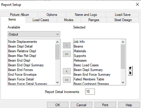
- Now click on report section from result
- Again click on items - provide Input and output - select items - ok
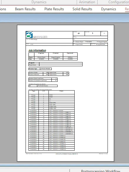
- We get a reprot
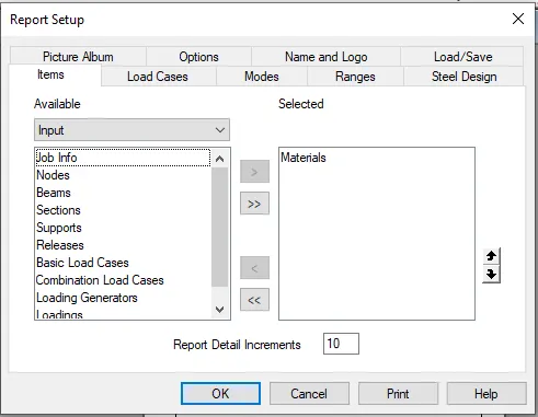
- Again click on items - Input - Materials and job info - ok
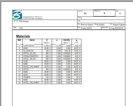
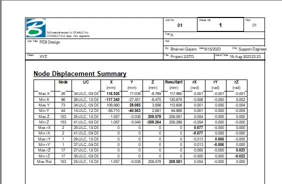
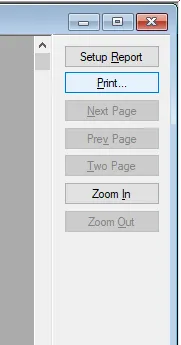
- For convert report in PDF format click on print
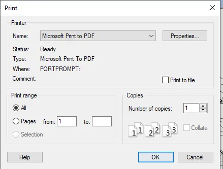
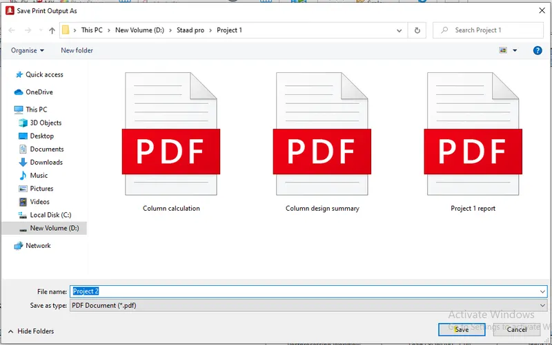
- Provide name - ok - Select appropriate location and name - save
Design using MS – Excel
5) Design using MS – Excel
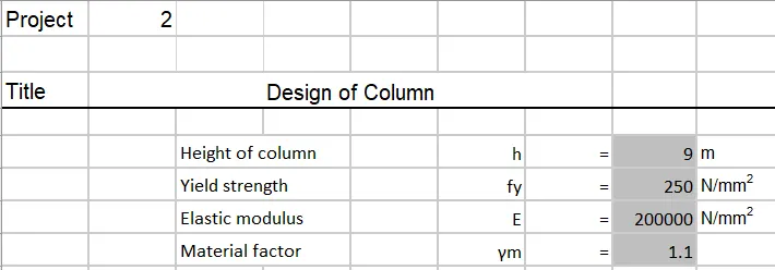
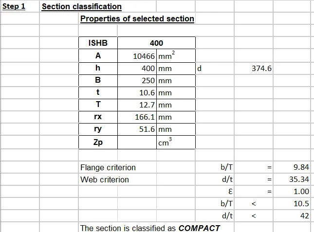
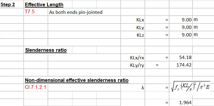
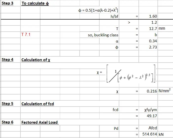
A) Design of Steel Column member in MS-Excel:-
B) Design of Steel Rafter in MS-Excel:-
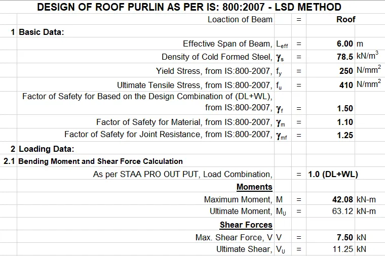
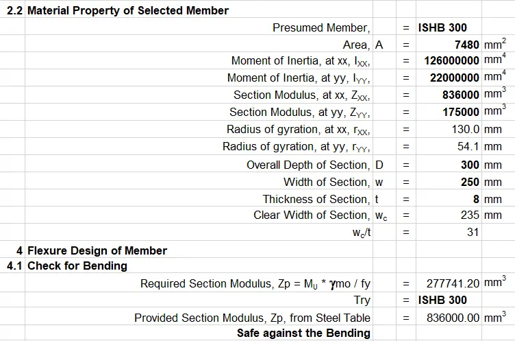
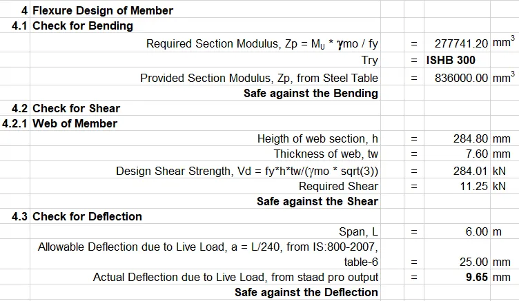
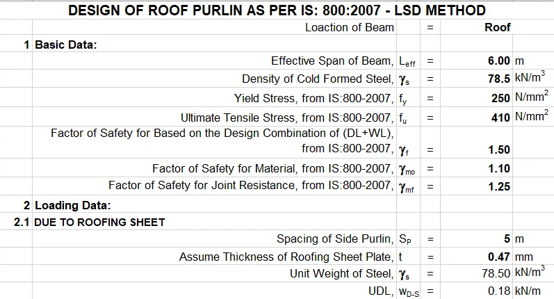
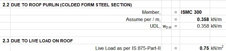
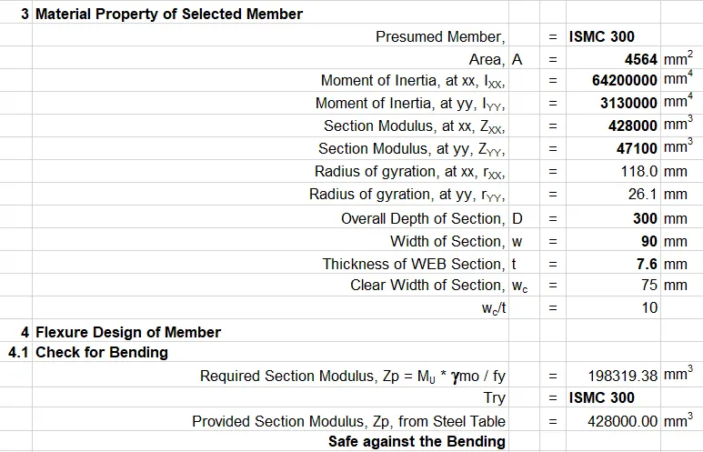
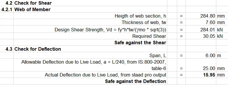
C) Design of Steel purlin in MS-Excel:-
D) Design of base plate in MS-Excel:-
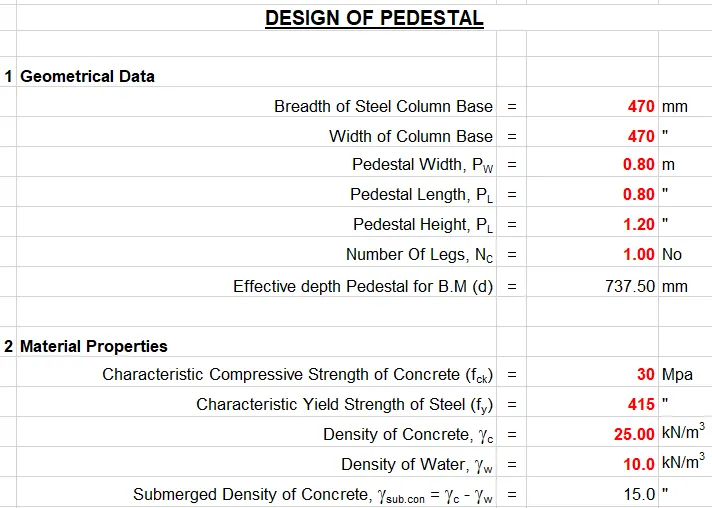
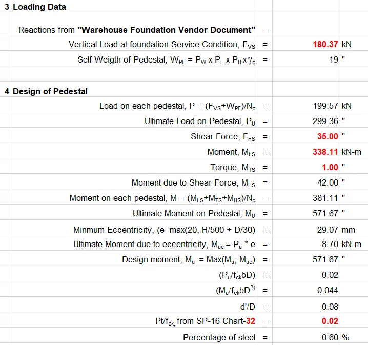
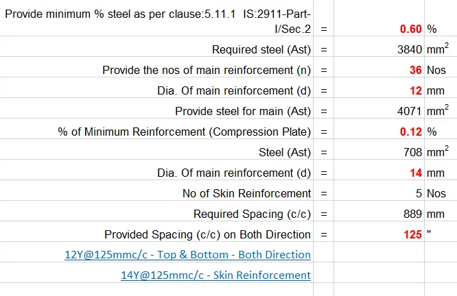
E) Design of Pedestral in MS-Excel:-
6) Design Foundations using STAAD Foundation:
Step:1- Open staad foundation
- Open the model
- Click on Staad Foundation
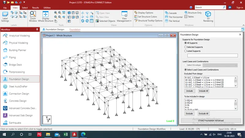
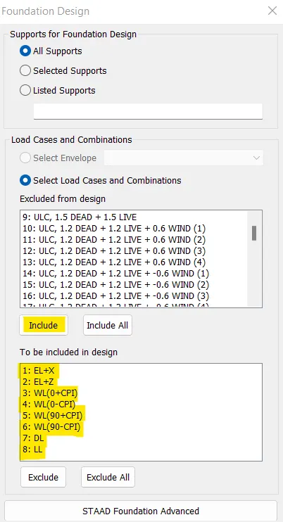
- Include only Prime load cases
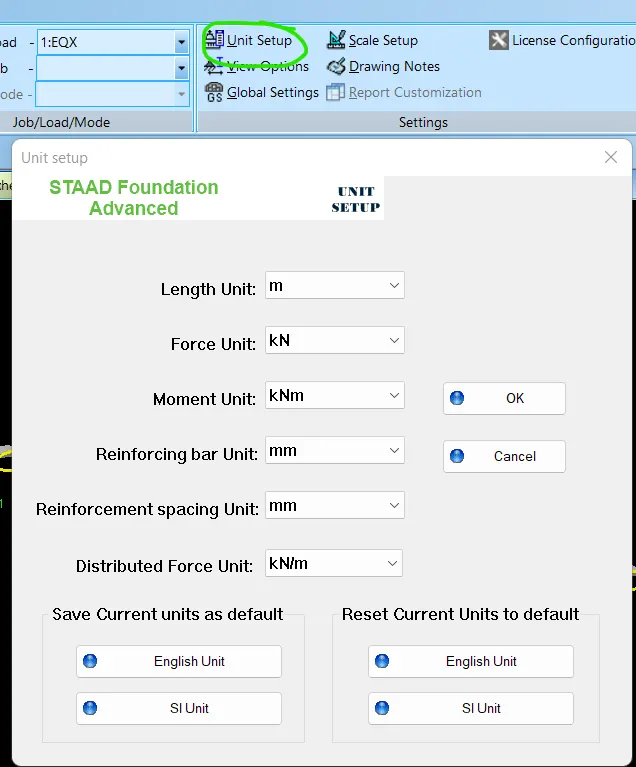
Step:-2 Unit Setup:
- Set the unit system
Step:-3 Generate load combination
Generate Service and ultimate Load combination
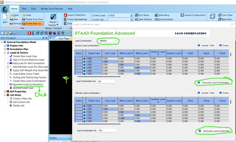
-Then click to column reaction load
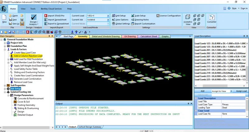
Step:4 - Create Job:
- Click on Job setup - Create a New Job
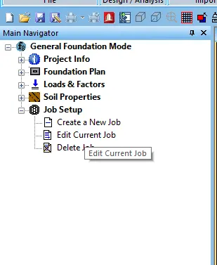
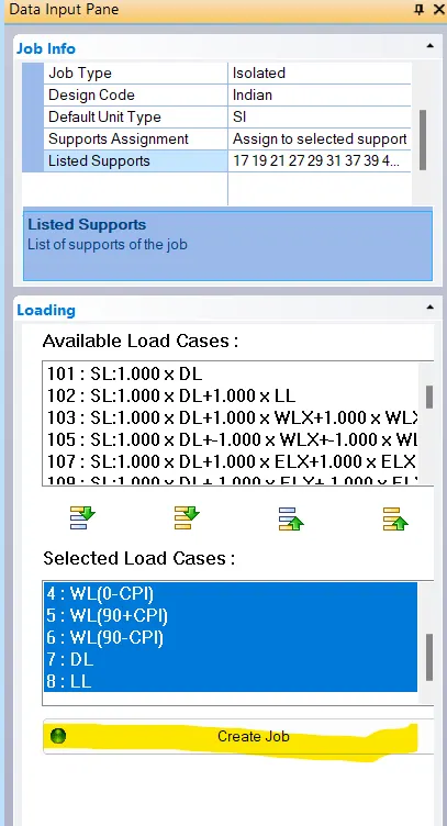
Step:5 - Apply Design Paramters
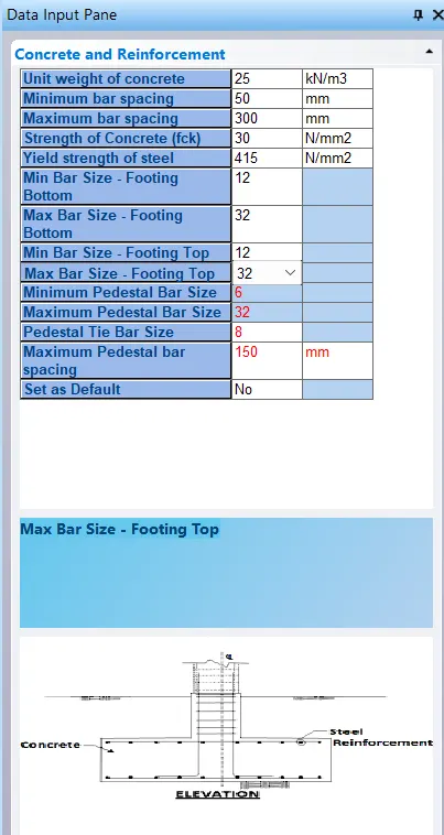
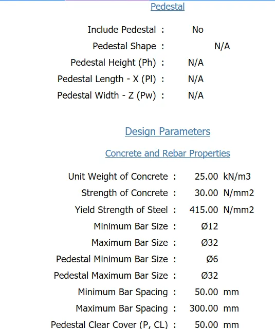
- Enter concrete and reinforcement details
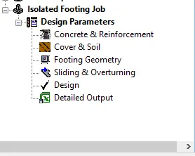
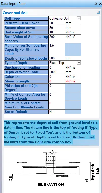
- Enter Soil property
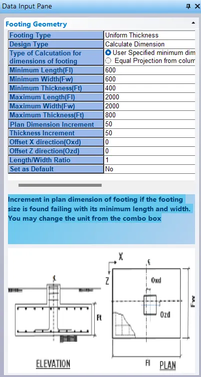
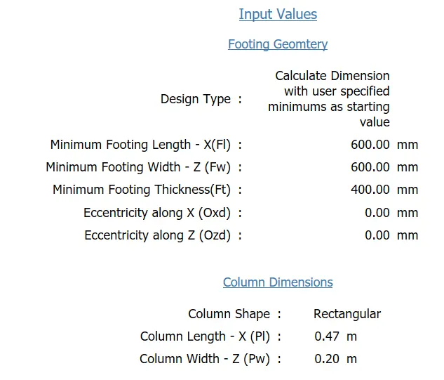
-Enter Footing Geometry
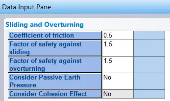
- Provide sliding & overturning data
- Click on Design
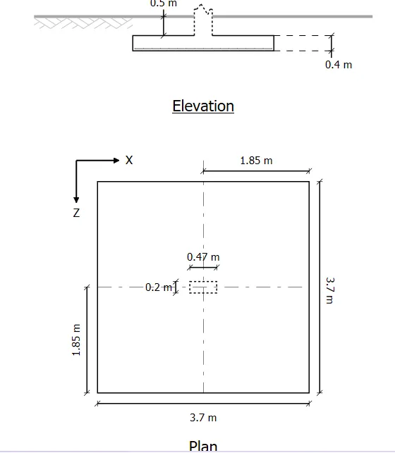
- Once design is completed you will see the details of footing
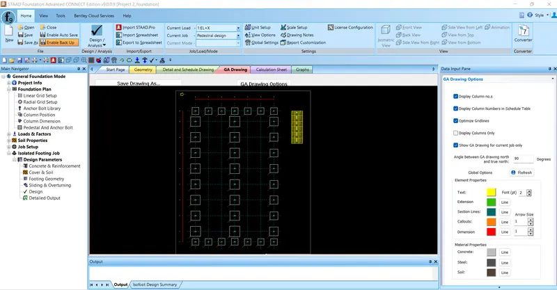
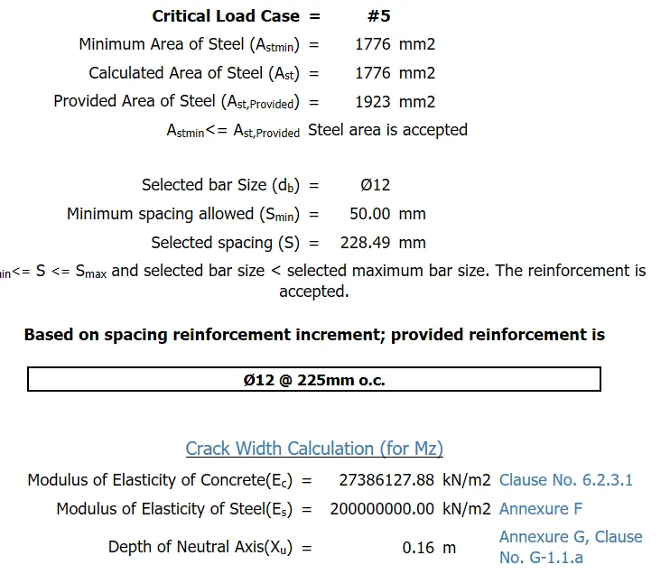
- Design output of footing
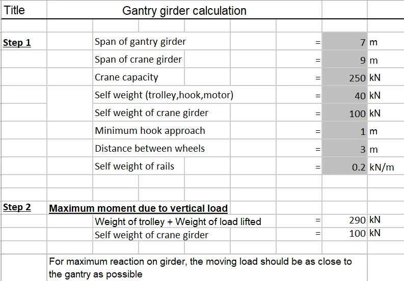
2. Design a simply supported gantry girder to carry electric overhead travelling crane
Given:
Span of gantry girder = 7 m
Span of crane girder = 9 m
Crane capacity = 250 kN
Self-weight of trolley, hook, electric motor etc. = 40 kN
Self-weight of crane girder excluding trolley = 100 kN
Minimum hook approach = 1.0 m
Distance between wheels = 3 m
Self-weight of rails = 0.2 kN/m.
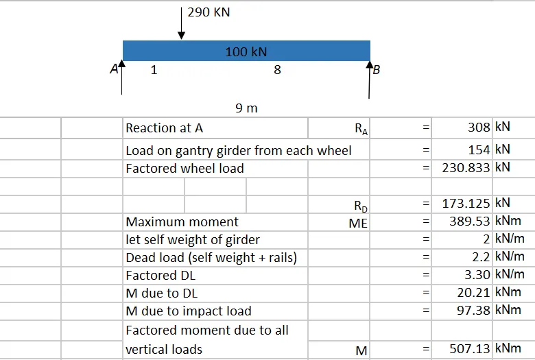
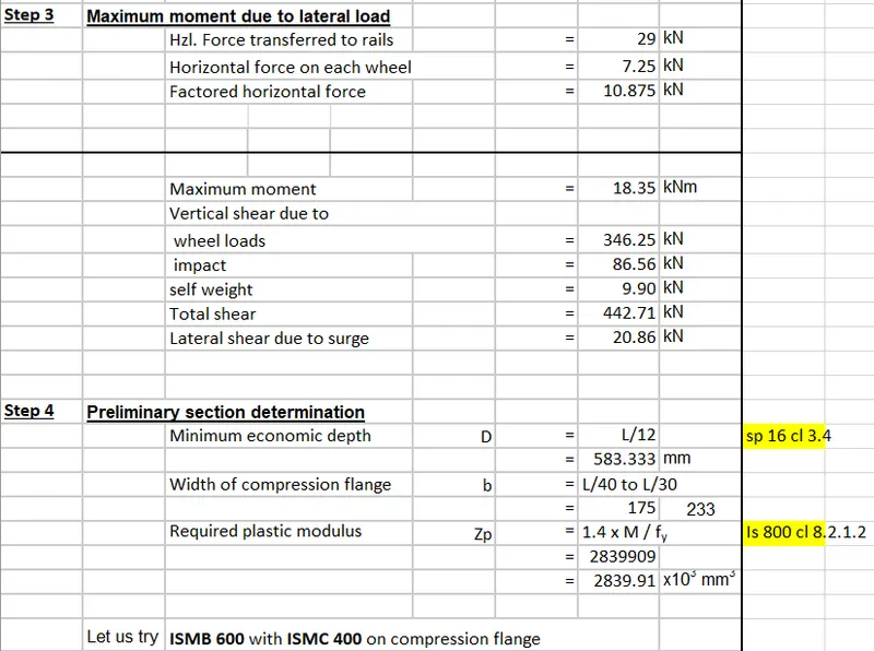
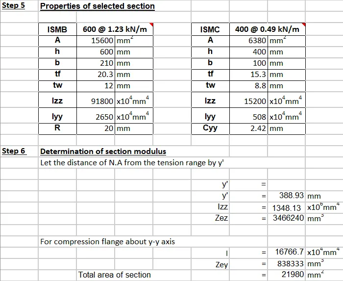
Ans: