Project 2
AUTOMOTIVE WIRING HARNESS FOR BACKDOOR
Aim: To route the wiring harness on the given backdoor assembly and prepare the flatten view drawing in CATIA V5.
Objective: The objective of this project is to route the wiring harness and prepare flatten view drawing for the Backdoor of the car. All types of packaging rules have to be considered while routing the harness and industry based practices shall be demonstrated in harness design. All necessary details like clearance, clipping/clamping selection, harness fixing requirements, harness continuity should be provided in order to design the wiring harness.
Introduction:
The trunk or boot of a car is the vehicle's main storage or cargo compartment it also have a hatch at the rear of the vehicle. It is also called a tailgate. These doors can be operated manually or electric powered. here we design the trunk or back door wire harness using the Catia.The Backdoor is an assembly of many parts such as inner panel, outer panel upper, outer panel lower and Reinforcement. Inner panel is attached to the outer panel using mastic sealant.
Types of doors based on working position
- Top Mounted Door
- Side mounted Door
- Bottom Door
WIRING HARNESS ROUTING
Procedure :
Step 1. Create context assembly product file
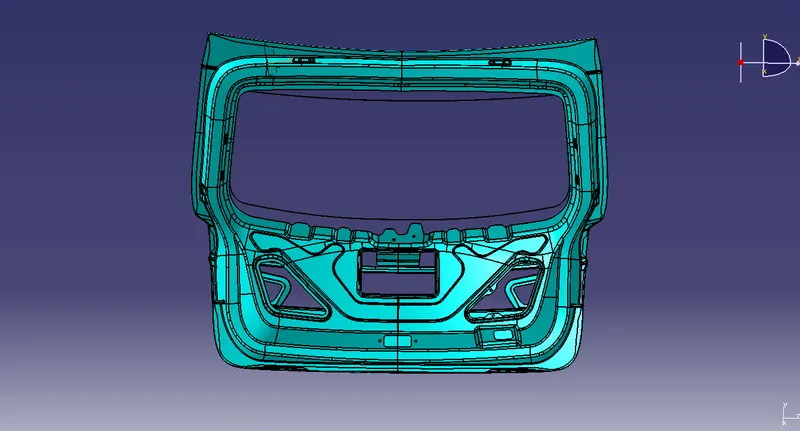
Create context assembly as shown in the image above. The context assembly will contain 3D CAD data for the backdoor
Step 2. Define the connectors electrically
Before adding connectors into the geometrical bundle define all the required connectors electrically.
To define any connector electrically,
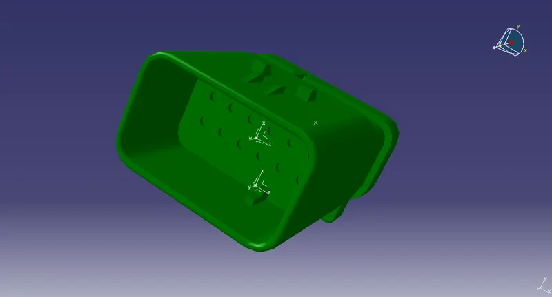
a. Create required geometrical parameters like bundle connection point, connector connection axis and cavity connection axis (if required) to the connector in the part design workbench as shown in the image below.
b. Now define connector with electrical properties such as connector connection point, bundle connection point and cavity connection point.
c.Go to electrical part design workbench and select connector command and input the no. of terminals as per the available connector.

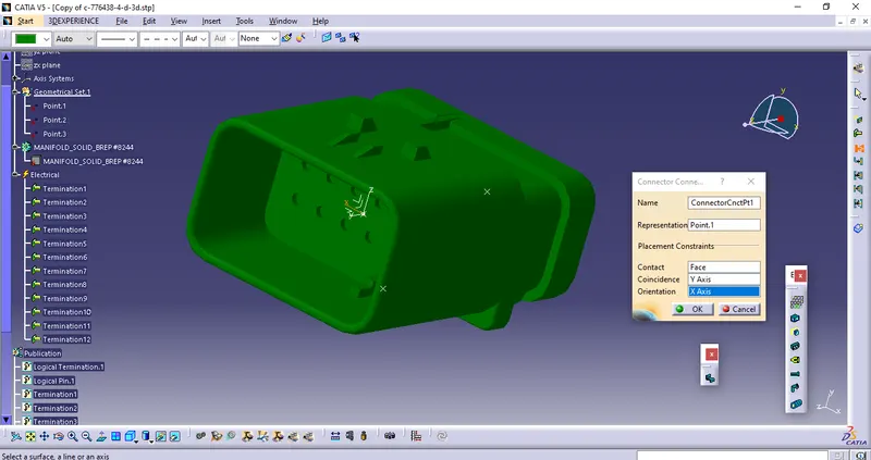
d. Defining connector connection point using connector connection point command and define the parameters as shown in the image below.
e. Define bundle connection point using bundle connection point command and define the parameters as below.
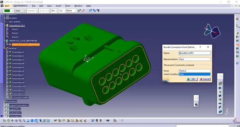
f. Define cavity connection point using cavity connection point command and defining the parameters as shown below.
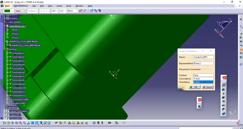
Hence the connector is defined electrically.
Use the same procedure to define all the connectors
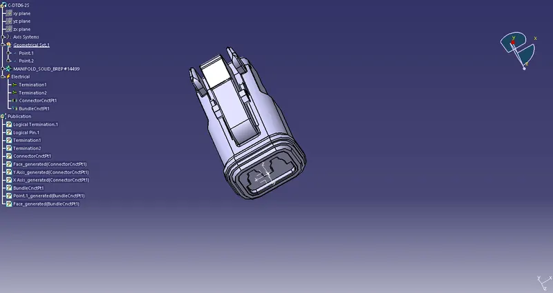
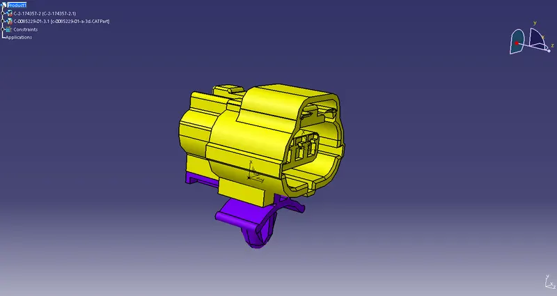
Create a catalouge using the Electrical part family and add the connetors
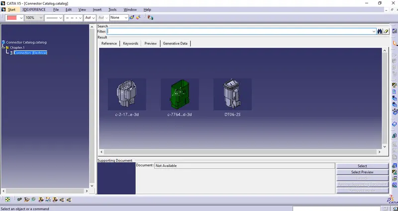
Step 3. Inserting connectors into geometrical bundle and positioning them
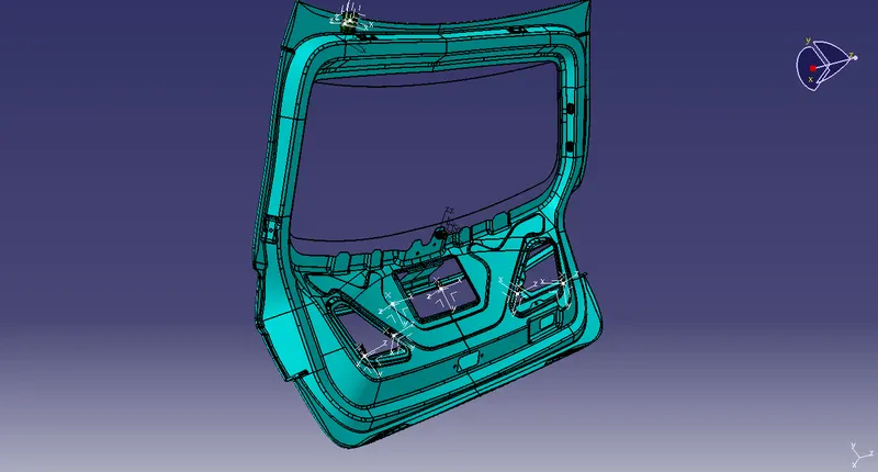
Adding P-clamps and Furr tree clip to provide positive clamping for the wiring harness.
P-clamps and Furr tree clip should be defined with electrical properties before inserting into the geometrical bundle assembly.
Define geometrical parameters such as entry point, entry plane, exit point, exit plane and base plane
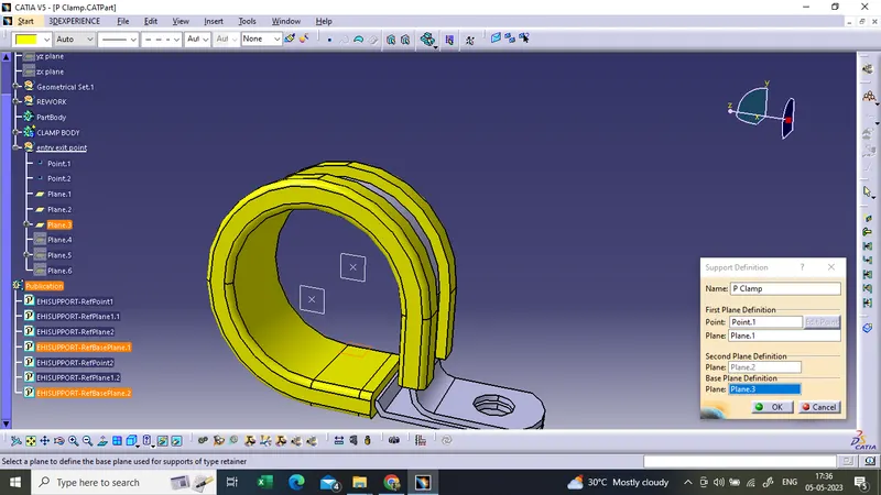
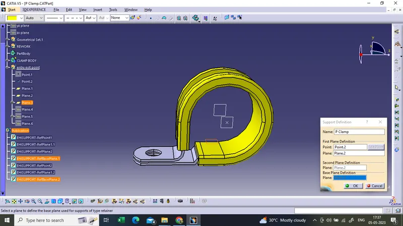
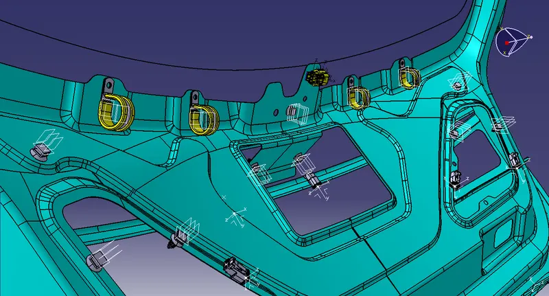
Routing the wiring harness to the connectors
Go to electrical harness assembly workbench and select geometrical bundle command and select the geometrical bundle in the model tree. Then select the multibranchable command to start the bundle routing and go to route definition.
- The bundle routing starts from interconnection connector and then to the P-clamps and to the guiding channels.
- Adding branches wherever necessary to connect the various connectors to the main branch
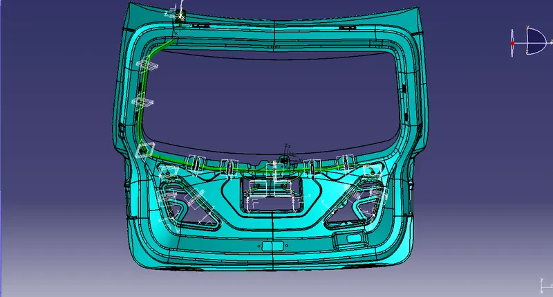
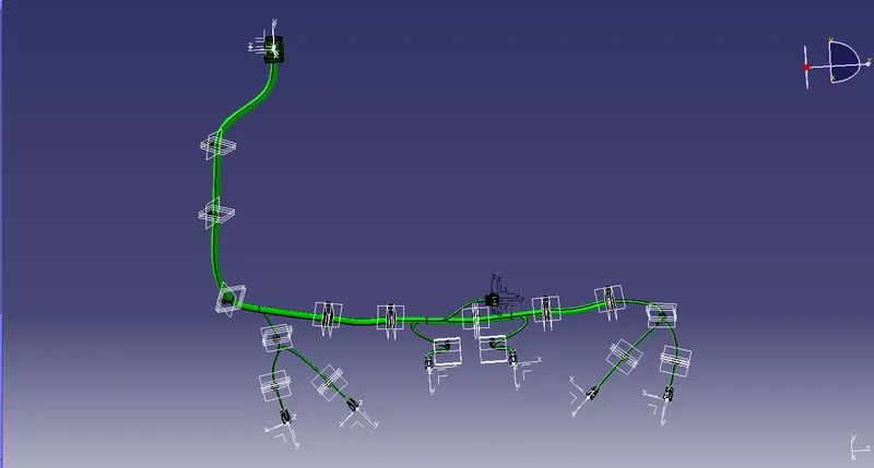
Check For bundel continuity
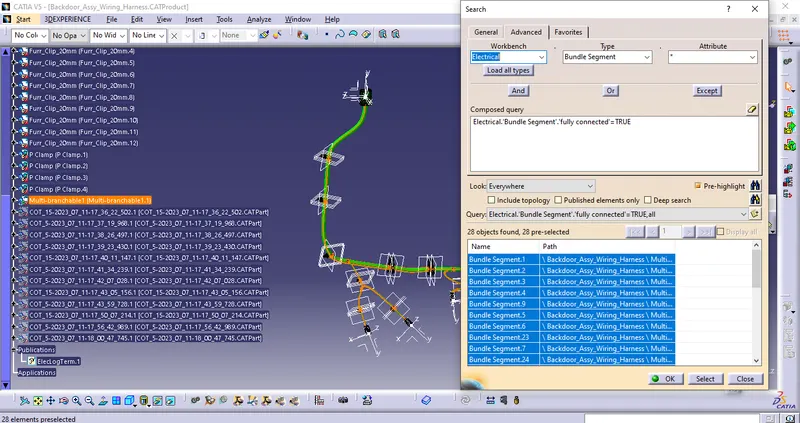
The Bundel is fully connected
Add protective covering such as Cot Tuebes which already added in the cataloge
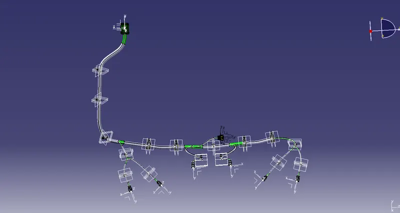
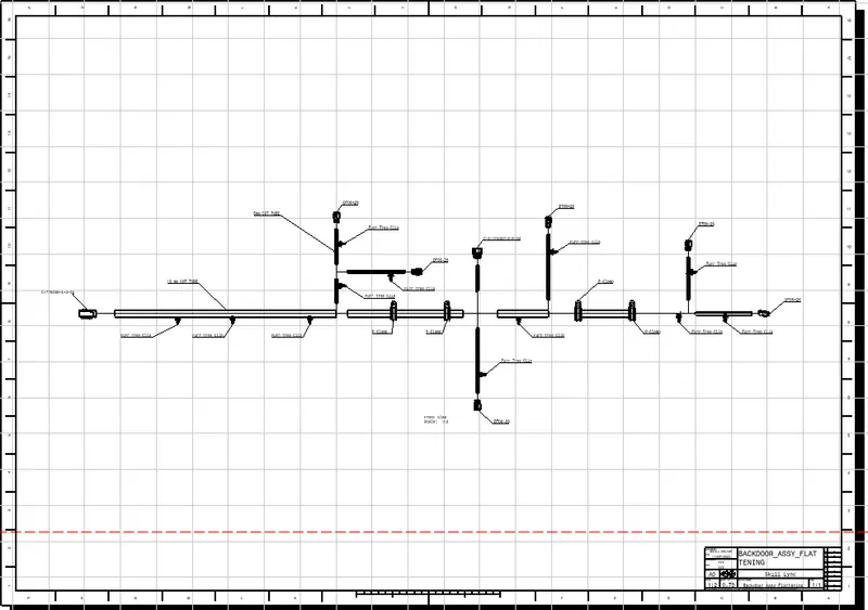
TO FLATTEN THE WIRING HARNESS AND DRAFT THE WIRING HARNESS ASSEMBLY.
HARNESS FLATTENING:
- WE GO TO THE HARNESS FLATTENING WORKBENCH AND DEFINE THE FLATTENING PARAMETERS.
- WE USE THE EXTRACT COMMAND TO BRING THE HARNESS ASSEMBLY TO THE FLATTENING WORKBENCH HERE.
- CHOOSING A SUITABLE PLANE WE FLATTEN THE HARNESS ASSEMBLY.
- BUNDLE SEGMENTS ARE ROTATED AT THE REQUIRED ANGLES. THE HARNESS ASSEMBLY IS THEN DRAFTED.
- FLATTENING PARAMETERS ARE DEFINED IN ORDER TO MAKE THE BUNDLE AND THE CORRUGATED TUBES VISIBLE IN THE 3D DRAWINGS.
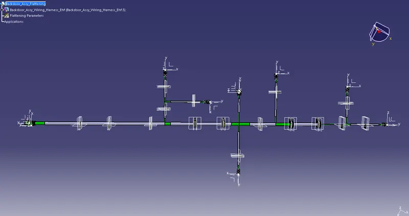
DRAFTING REPRESENTATION: