Project 2
BACK DOOR WIRING HARNESS ASSEMBLY
AIM:
- To route the wiring harness for the given Tailgate.
- Application of all Packaging rules, Industry best practices studied in this course shall be demonstrated in design.
- Apply Protection coverings as required.
COMPONENTS:
DT06-08SA-CE13-03
DT06-4S-C017-02
DT06-3S-PP01-01
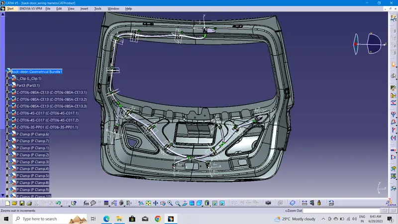
p clamp:10
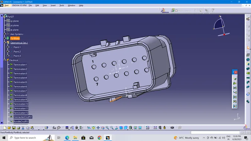
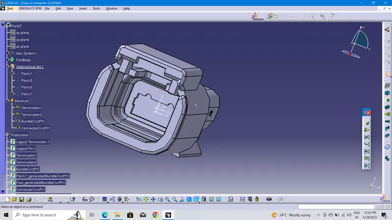
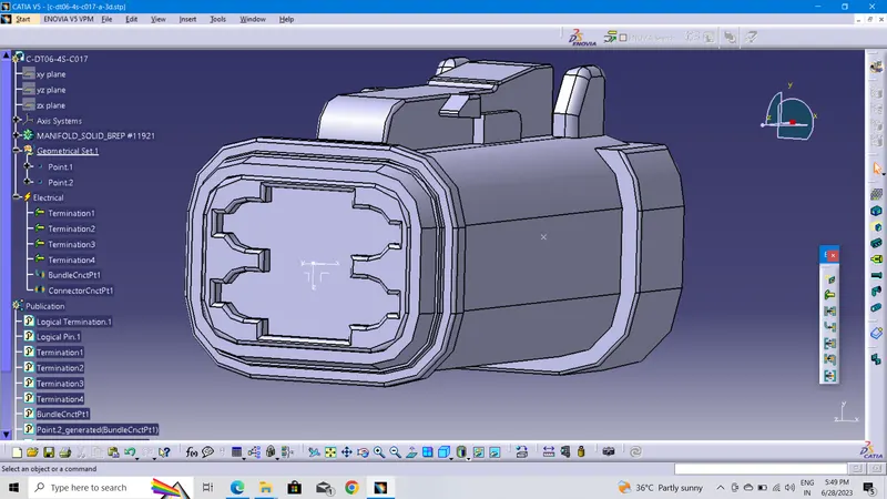
All the connectors should be download into te .com and also connectoers and p clamp must be electrically defined done before assembly
connector connection points
bunnle connection points
connection cavity points all must defined.
PACKAGING RULES:
- Wiring harness routing shall provide ease in manufacturing, accessibility, easy removal, and easy maintenance of attached equipment and wiring harness.
- Routing through small structural holes and openings shall be avoided, minimizing chafing and handling the wiring harness during installation.
- Avoid the harness routing and clipping in the Blind zone of the Operator during harness assembly or in service.
- Routing shall offer protection against possible damage through common misuses such as being handhold and temporary support for test equipment.
- Provide additional slack to the harness according to the surroundings and harness bending requirements.
- Ensure the routing meets the clearance requirements with different surrounding parts.
- Avoid routing over the bolts, near to the bolted joints. It may damage the harness or puncture the harness. Keep harness away from panel mounting screws.
- Avoid harness routing near sharp edges, if not possible provide protection to the harness.
- The maximum distance between two clips on a straight branch is 200mm.
- Provide Clips and clamps if the harness is going to bend at multiple locations.
- The use of too many sheet-metal brackets should be avoided.
- The branch length should be more than 50 mm.
- Min distance between clip and branching point to be 25 mm.
- Min distance between two branch breakouts should be 50 mm.
JUSITIFICATON:
Connectors and p calmp where to be located idenditication done.
but should be avoided into sealing flange fig shown area connecor placed but particular area cut out to be need for connecter fixing purpose design engineer aspects CFT where the location to cut out need for mounting fix and all the thinks should be clarified into CFT
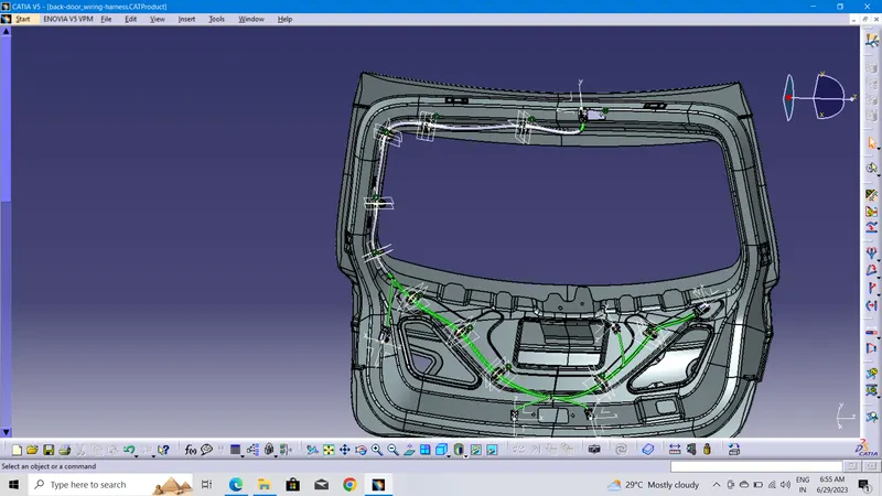
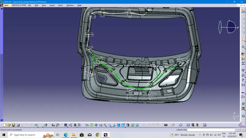
Two connectors placed to for Tail lamps.One connector for Main wiring loom connection, another one Wiper motor activations. Another one connector for back door latch activation another one break lamp or rear parking sensor activation.
clamps all are positioned some of area wiring bunndle with have proper some other area will having more bend so clamps will placed before 20to 30 mm but onthat area wiring bunndle have a bend.then only placed near to near not beyond to 175 mm.
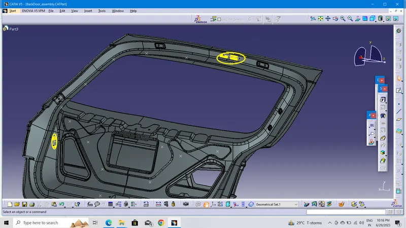
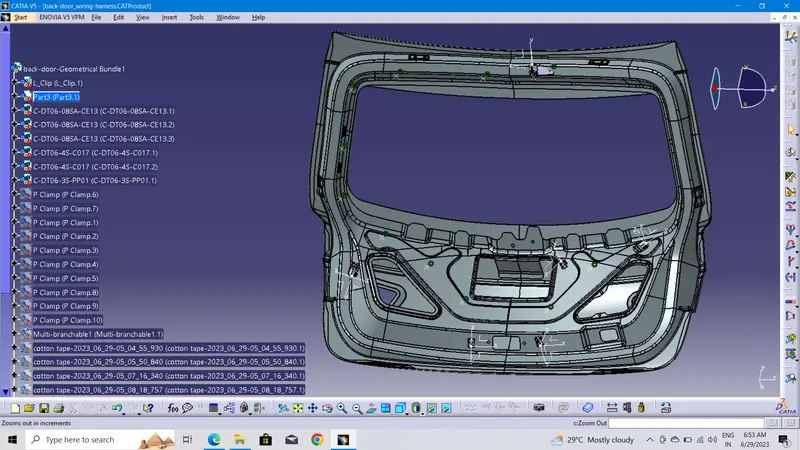
All the connectors and p clamp to be located by manupulatoin and smart move and also by compass move also used.
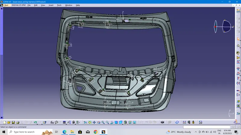
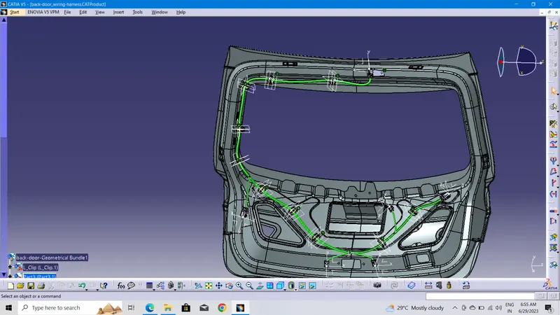
WIRING ROUTING:
After that routining to be done.
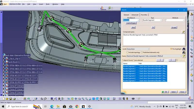
BUNDLE CONTINUITY CHECK:
After wiring Roughting must check bunndle continty to be checked done both True & False condition.
PROTECTION COVERING:
Apply Protection coverings as required to be applyied by pvc tapes& cotten tapes.
FLATENED FILE:
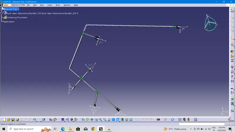
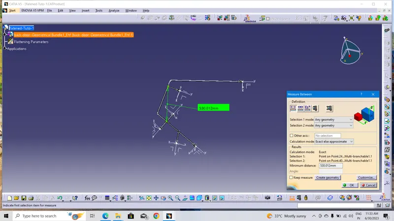
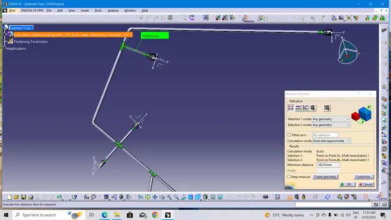
Aftrer complting my back door wiring harness routing Flatened parameters to be created for Wiring harness roughting should be flatened.
DRAWING FILE:
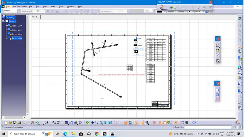
Flatened model should be draft into drawing file.
CONCLUSION:
The harness is routed for the given Tailgate and flattened the Harness.
created the drawing for the harness in the sheet.