Project 2
PROJECT 2
Objective:
Statement of assignment:
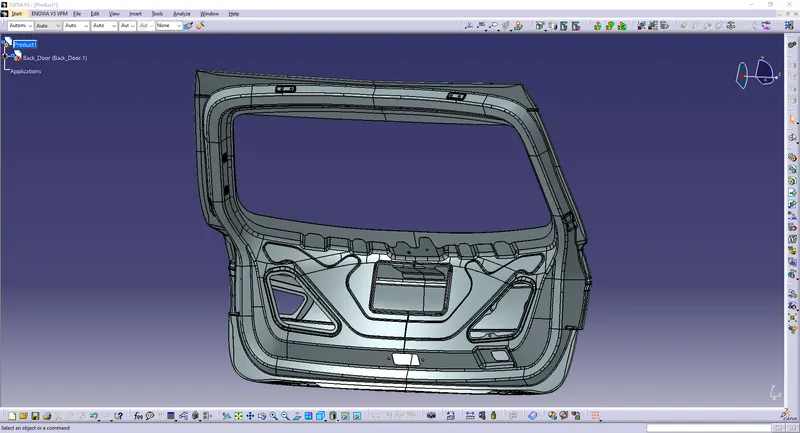
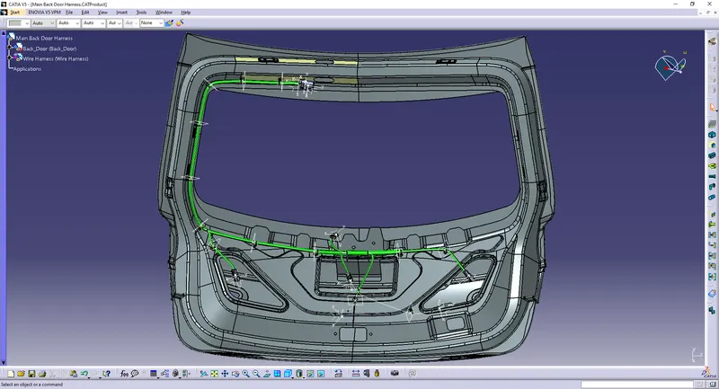
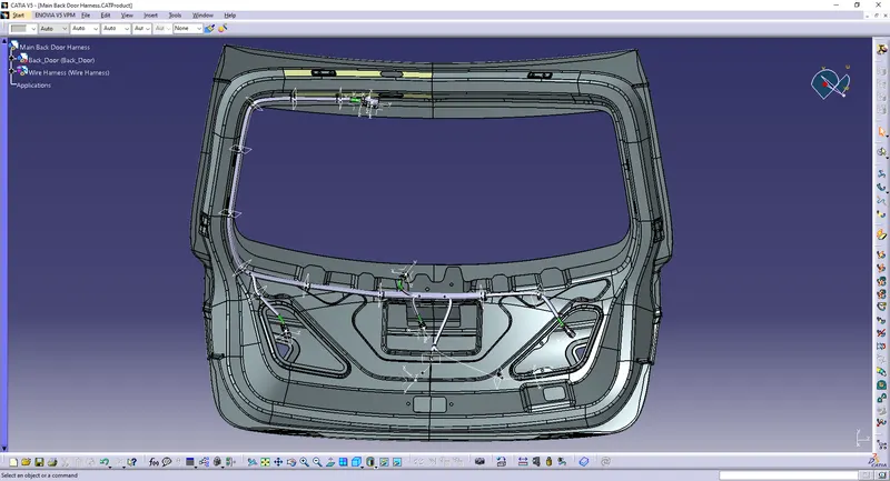
Route ofthe Wiring harness on the given car body and prepare a flattened view drawing in
CATIA V5. Application of all packaging rules, industry best practices studied in this course
shall be demonstrated in design. Apply Protection Coverings as required.
Available connector 3D data can be used, or you can download the connectors
from www.te.com
Prepare & Submit all necessary reports like clearance, Clipping/clamping selection,
Harness fixing requirments, Harness continuity, and Assumption if any along with CATIA
3D data.
Procedure:
Given the electrical properties to the connectors, and clip.
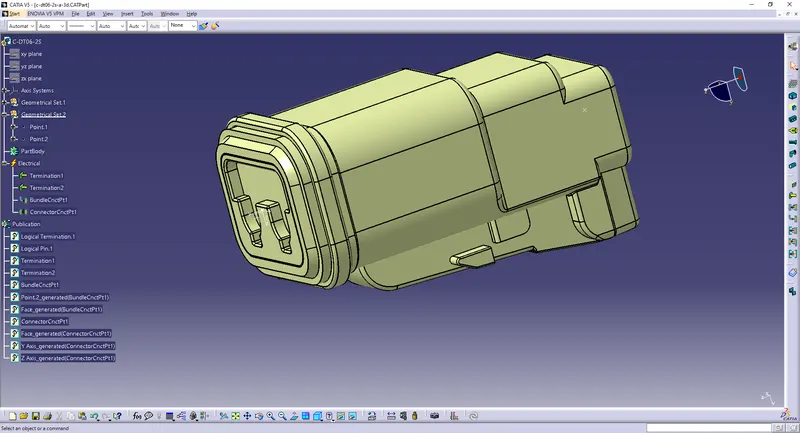
Connectors 1:
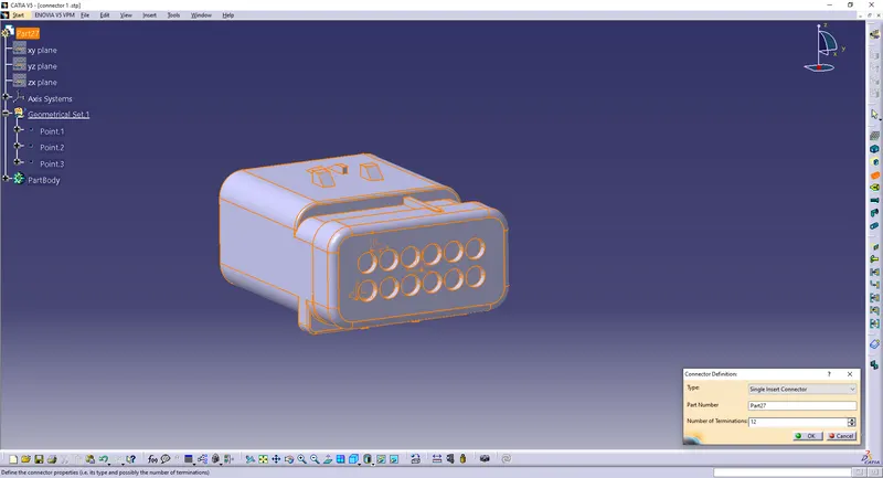
Create a point on the mating surface and a point at the back as the bundle entry point.
Create an axis on the point.
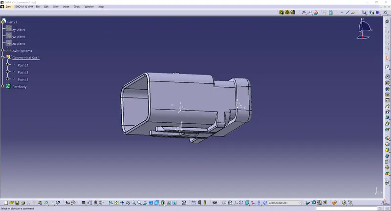
Define the part as a connector with 12 terminations.
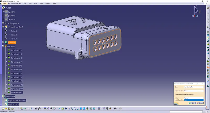
Define Bundle Connection Point.
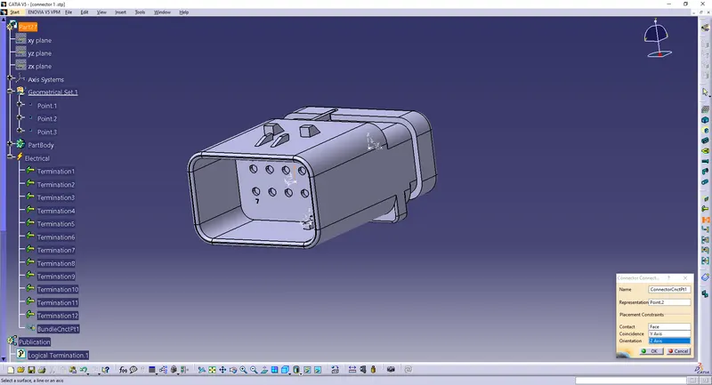
Define Connector Connection Point.
Define Cavity Connection Point (Not Necessary).

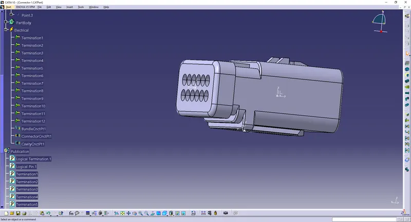
Connector 2:
Create a point on the mating surface and a point at the back as the bundle entry point.
Create axis on the point.
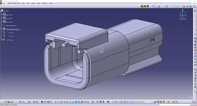
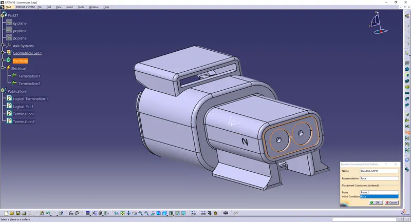
Define the part as a connector with 2 terminations.

Define Connector Connection Point.
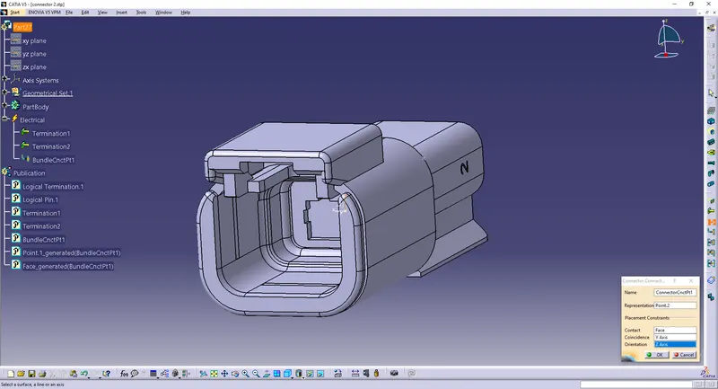
Define Connector Connection Point.
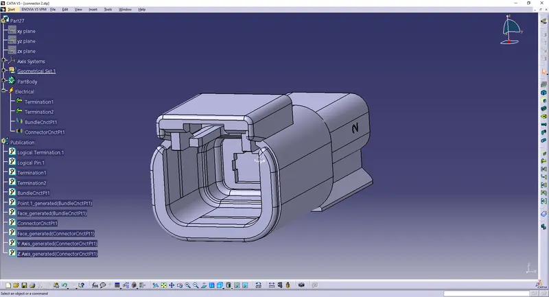
Connector 3:
Create a point on the mating surface and a point at the back as the bundle entry point.
Create an axis on the point.
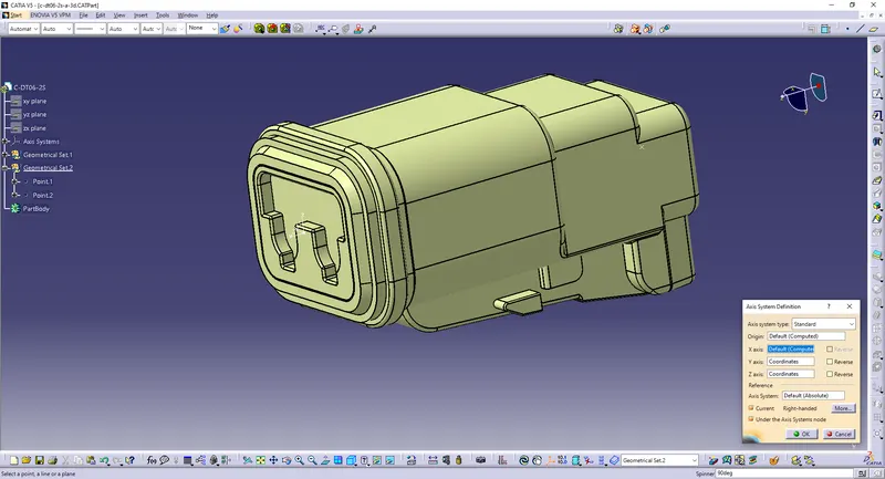
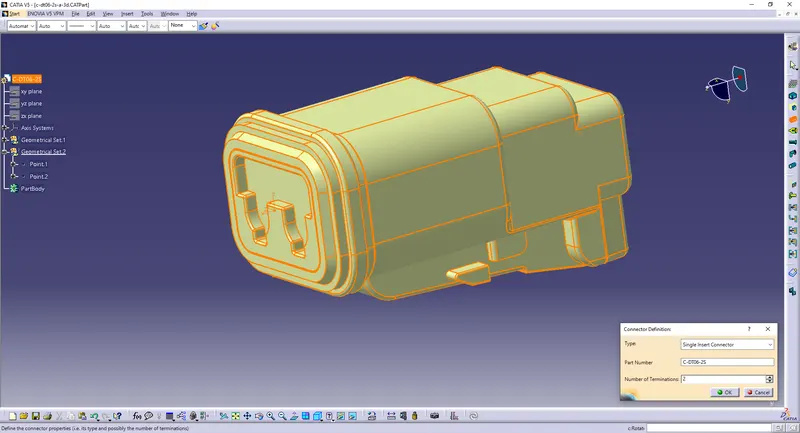
Define the part as a connector with 2 terminations.
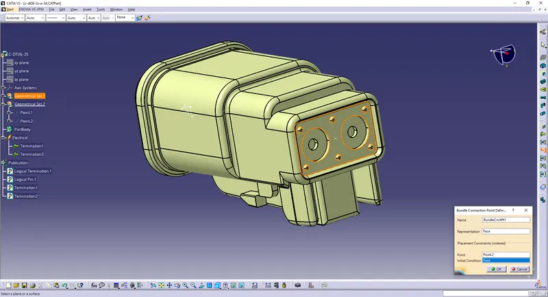
Define Bundle Connection Point.
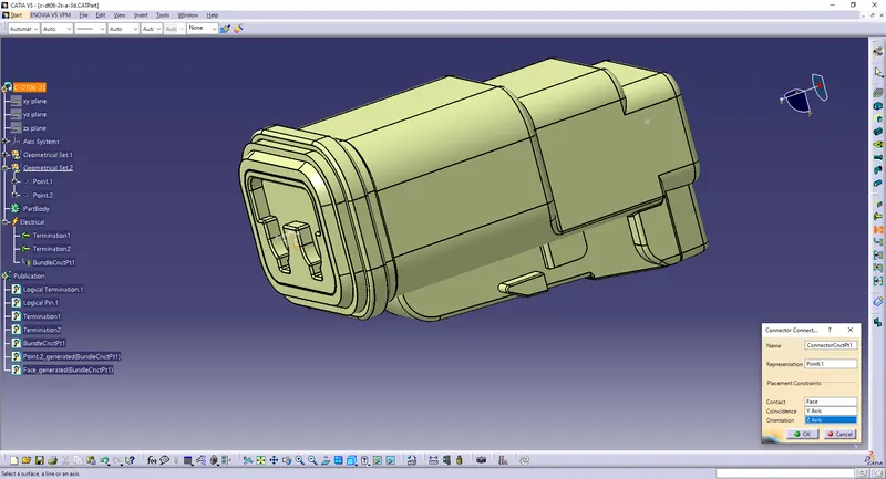
Define Connector Connection Point.
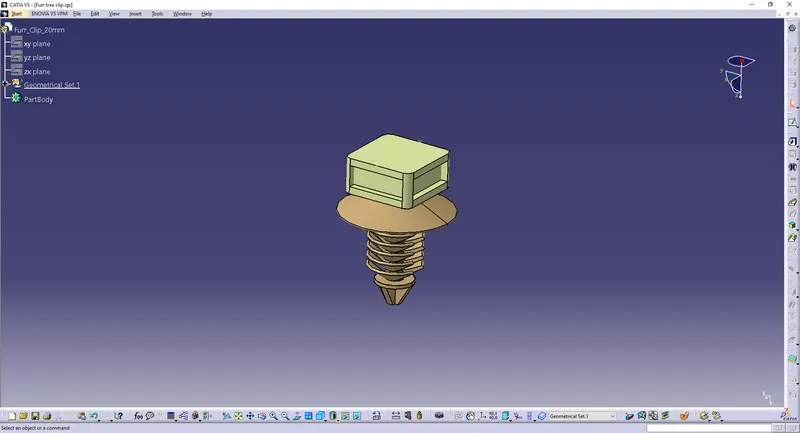
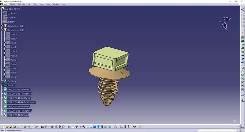
Furr Tree Clip:
Create 2 points on the top surface.
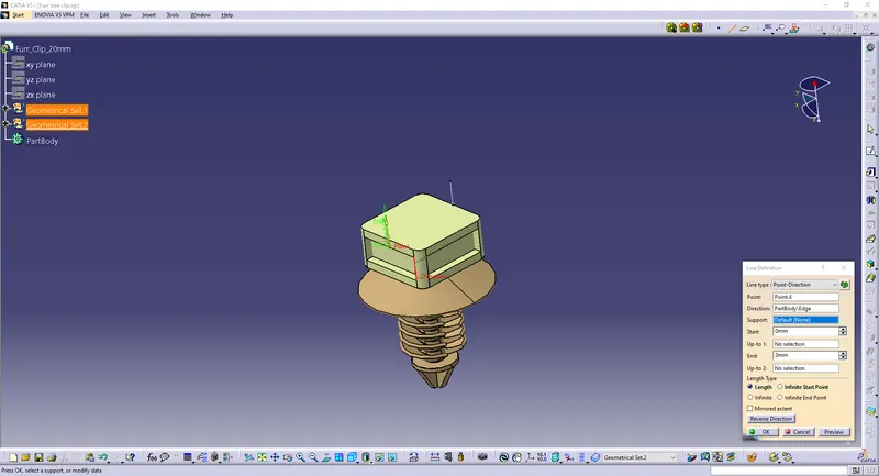
Make 2 lines through these points.
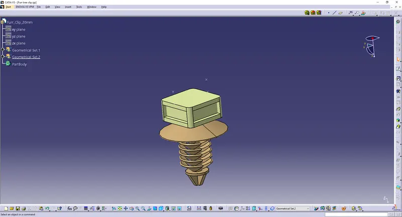
Make 2 pointson the ends of these lines.
Create 2 planes.
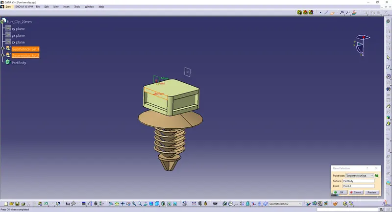
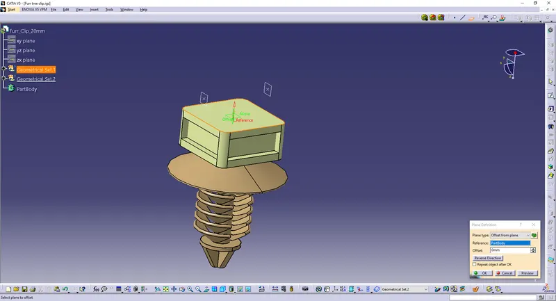
Select and define the clip as a support part.
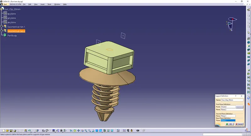
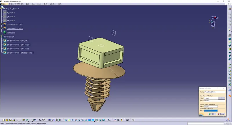
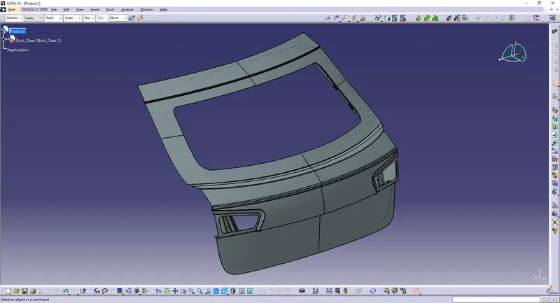
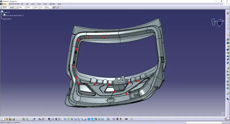
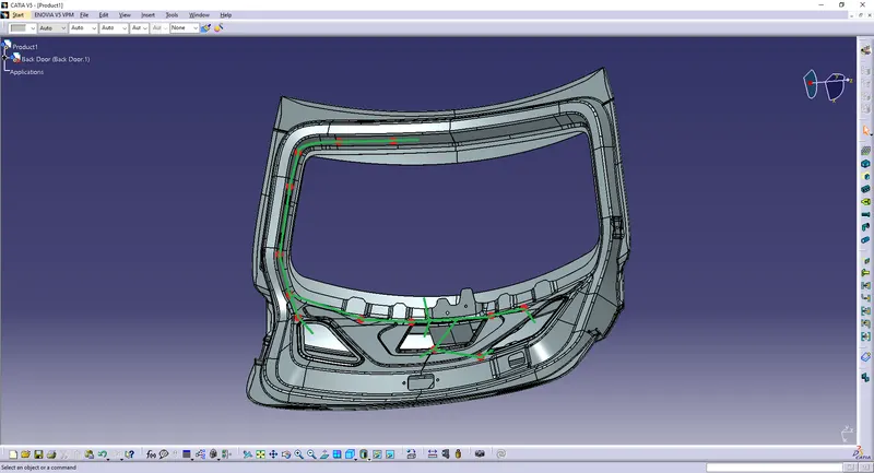
Deciding the routing path and clip position by observing the Back Door:
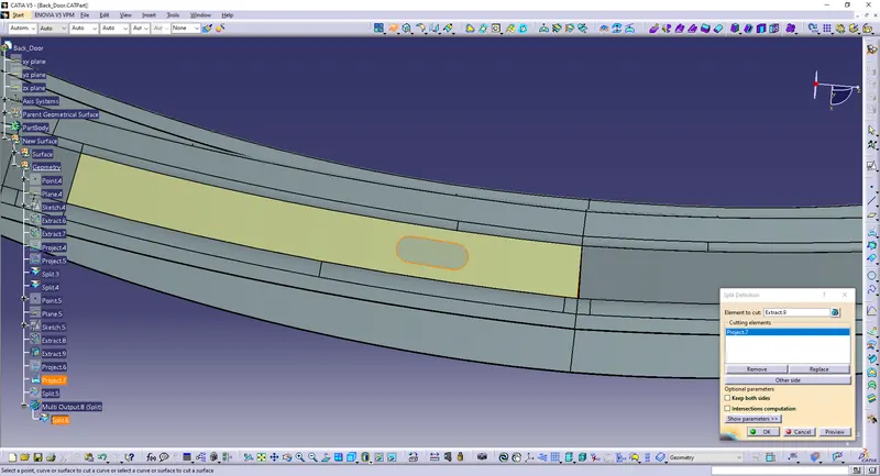
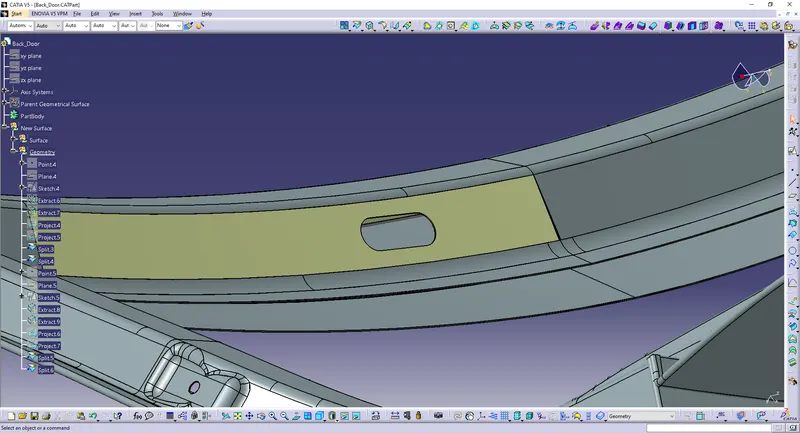
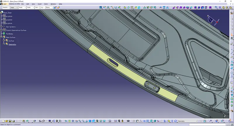
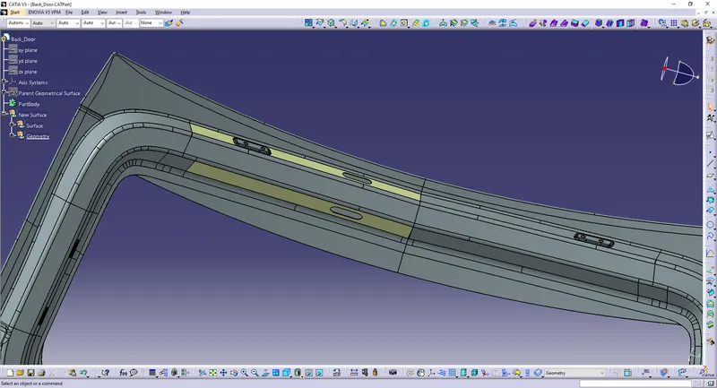
Make slot holes:
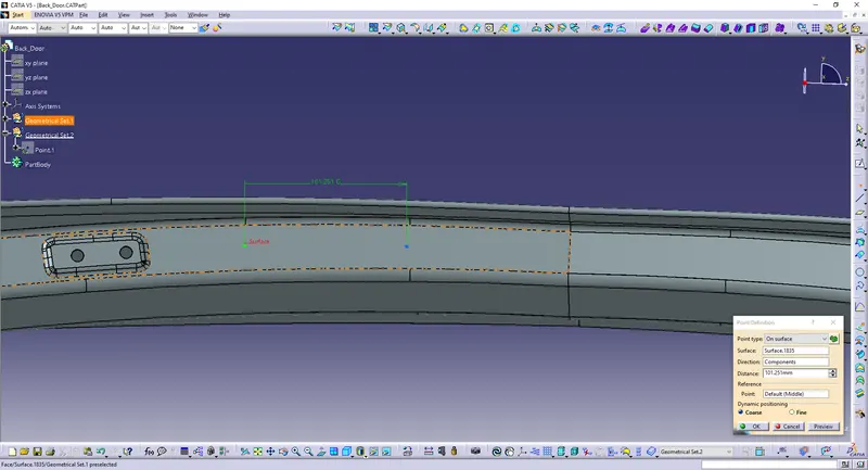
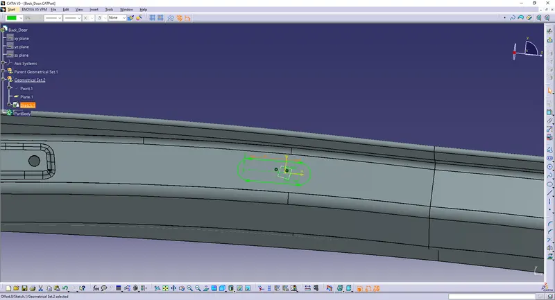
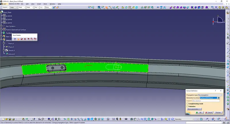
Extract the surface.
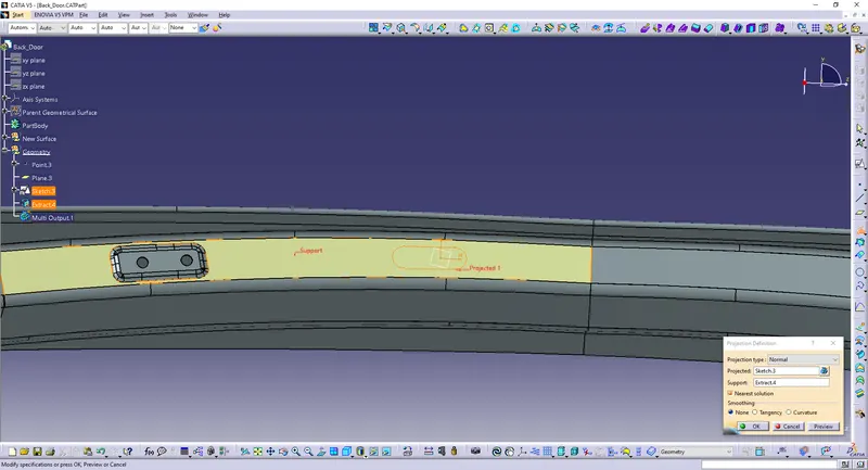
Project the sketch.
Split the surface.
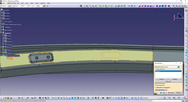
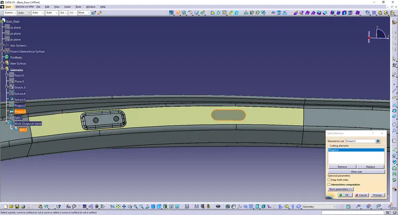
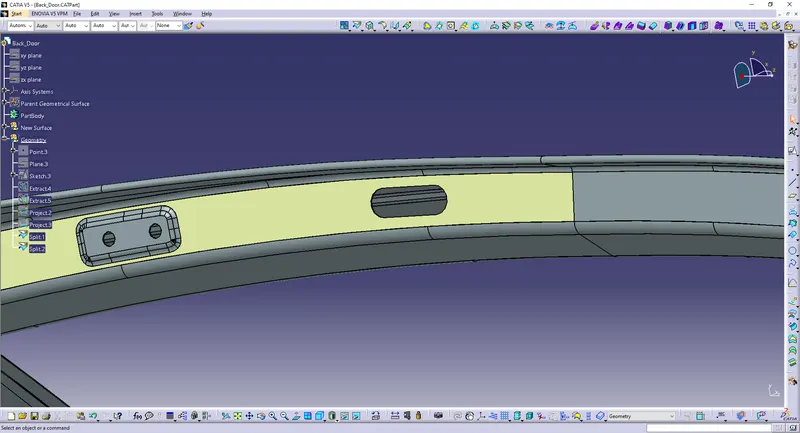
Do the same on the lower part.
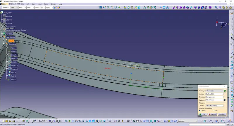
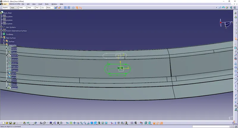
Extract the surface.
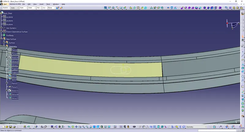
Project the sketch.
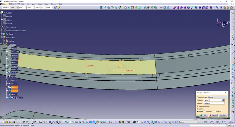
Split the surface.
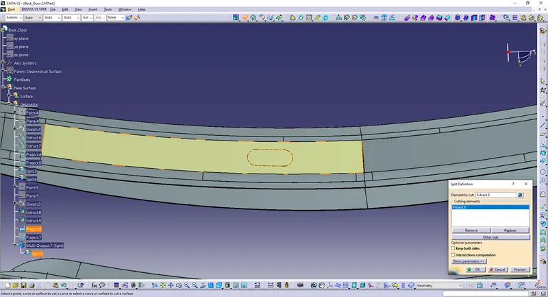
Start to align the clips:
Insert the clips and align them.
Use the 'Manipulation' and 'Smart Move' option to align the chip.
Making sure the clips are placed between 50mm-200mm as per the design rules.
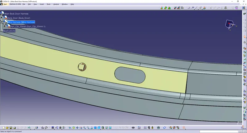
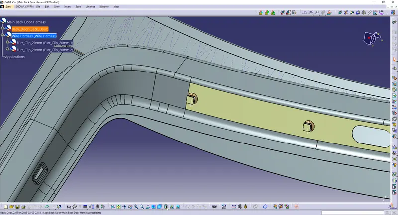
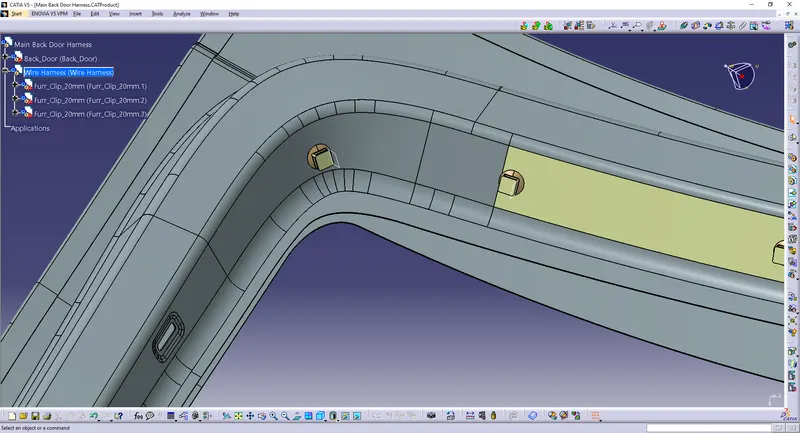
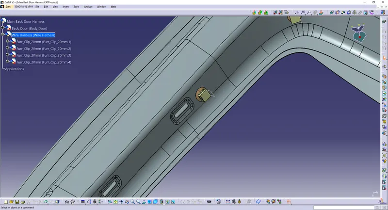
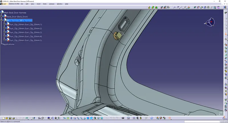

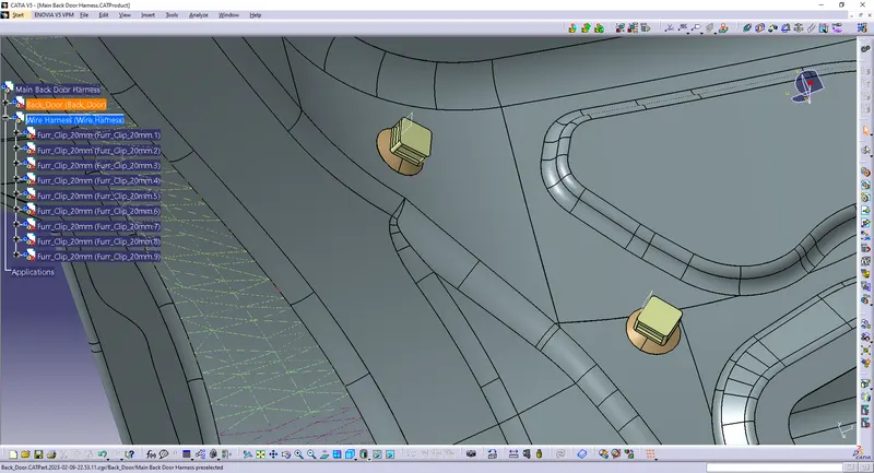
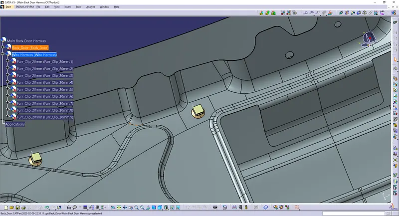
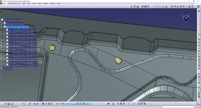
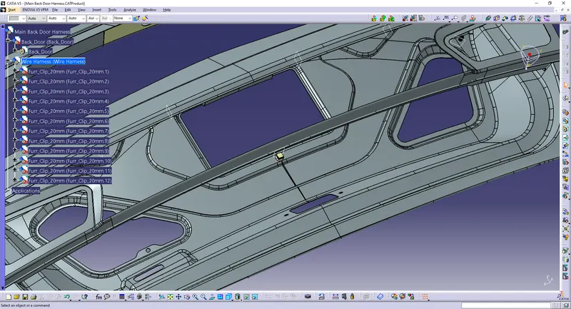
Insert the connectors and align them:
1 interconnection connector.
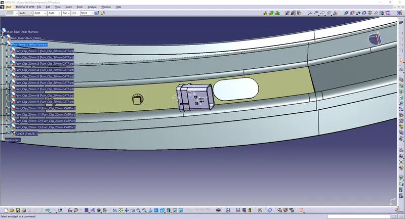
2 tail light connectors.
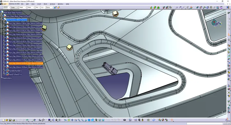
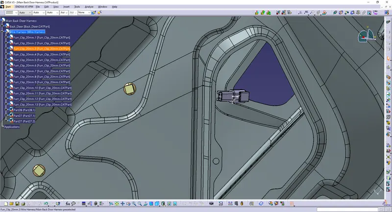
1 window wiper connector.
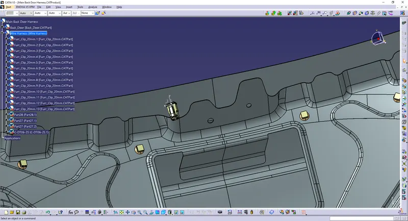
1 number plate light connector.
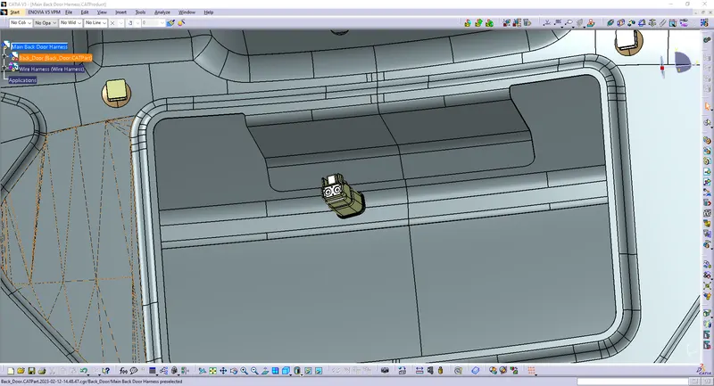
1 power lock/latch connector.
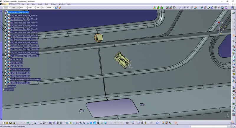
1 tailgate button connector.
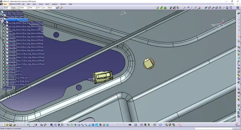
Start routing the bundle segment:
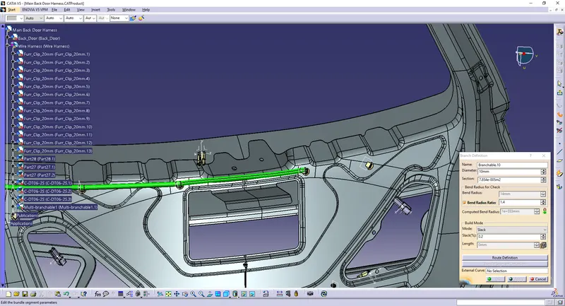
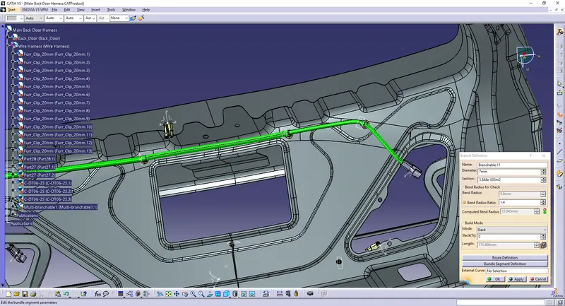
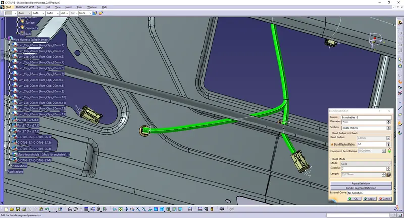
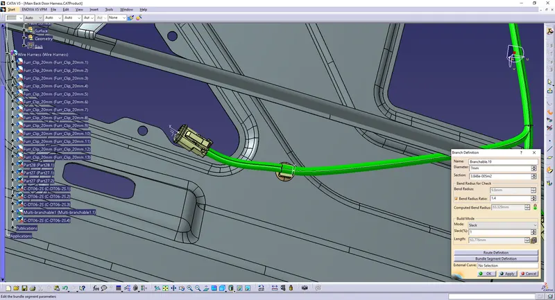
Create branch.
The bend ratio is 1.4 .
Slack 1-5% is provided at the necessary location.
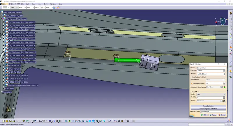
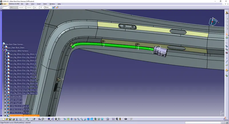
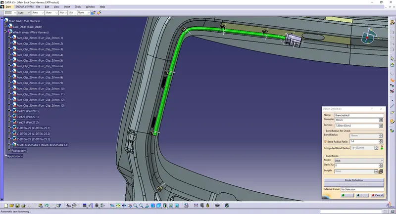
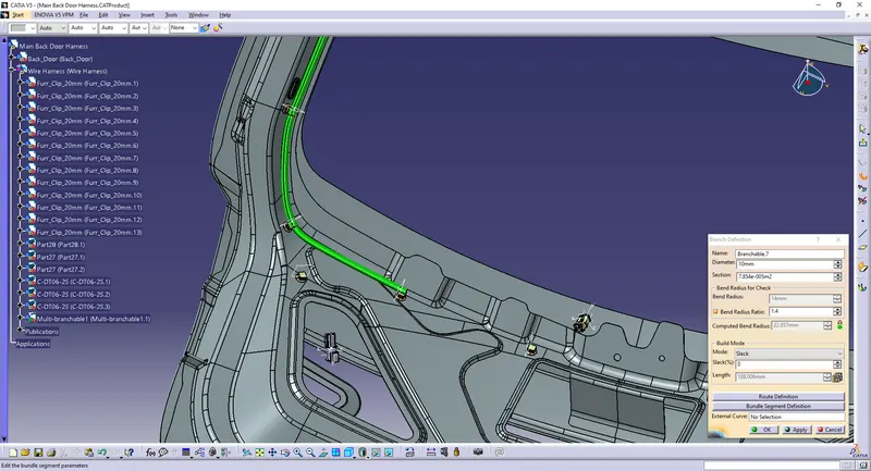
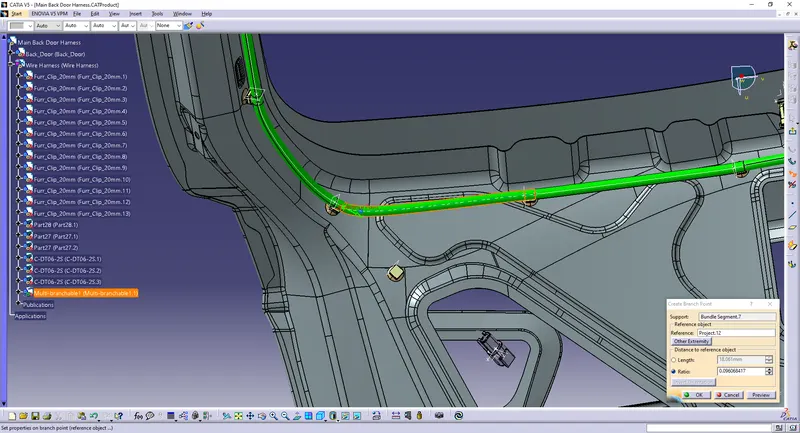
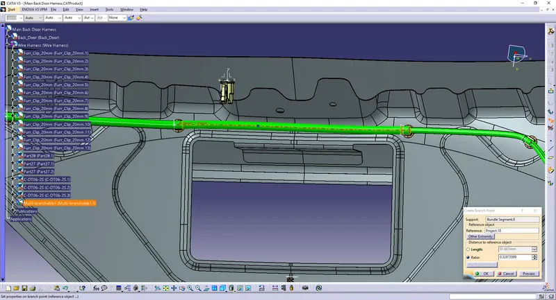
Create branch points where ever necessary.
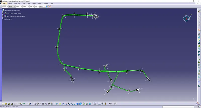
Continue the branch and connect to the remaining connectors.
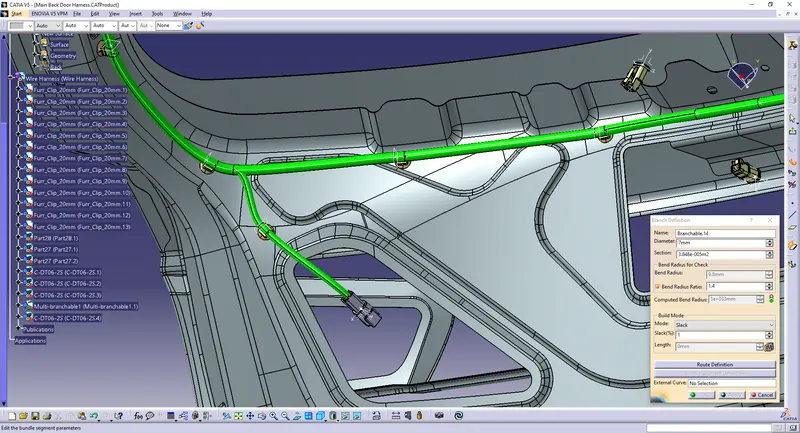
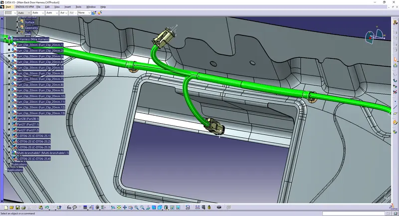
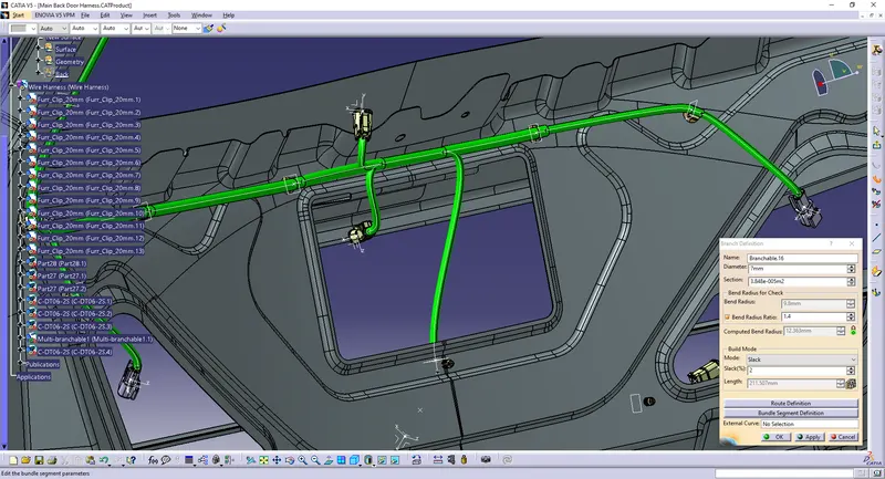
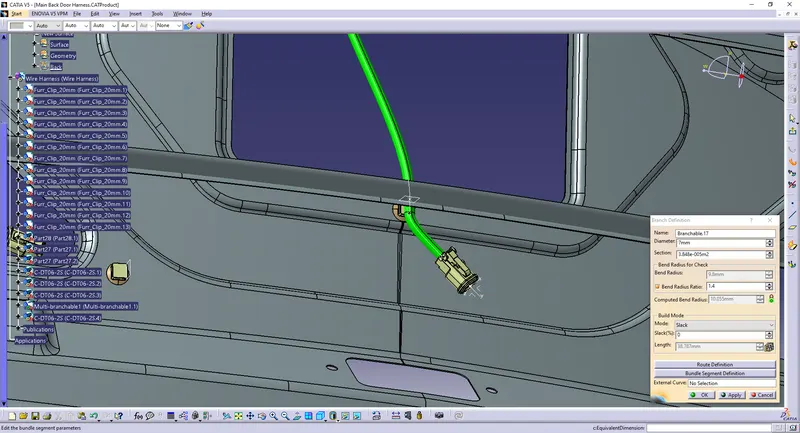
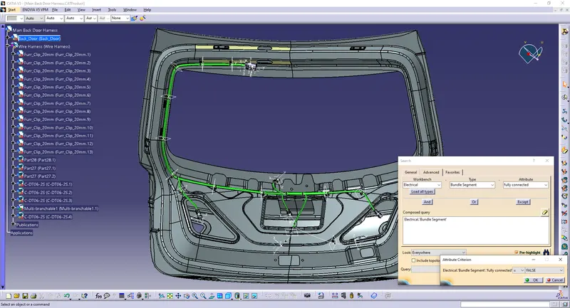
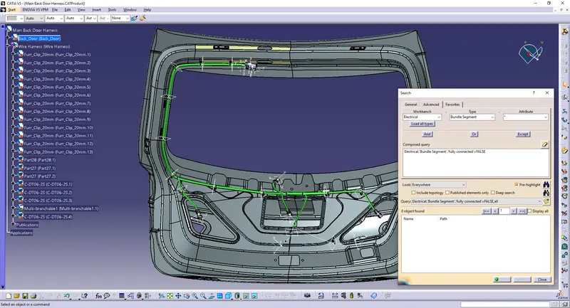
Cheking the connections:
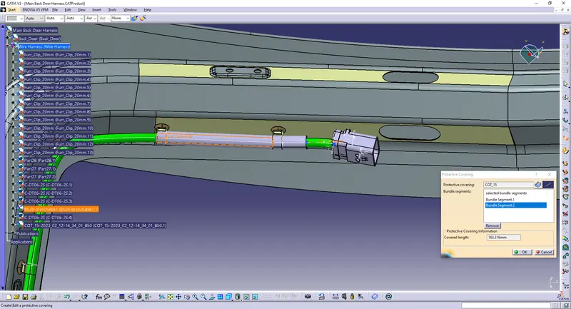
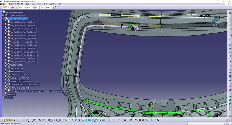
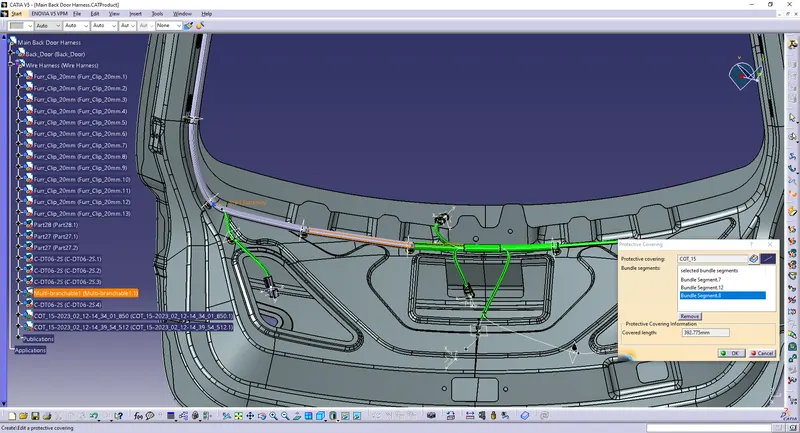
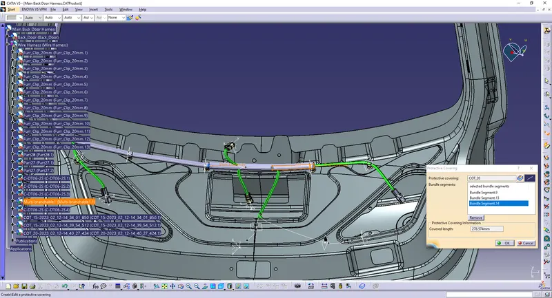
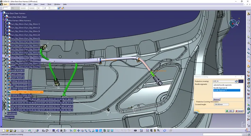
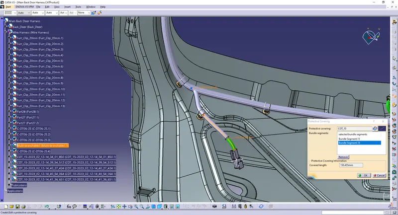
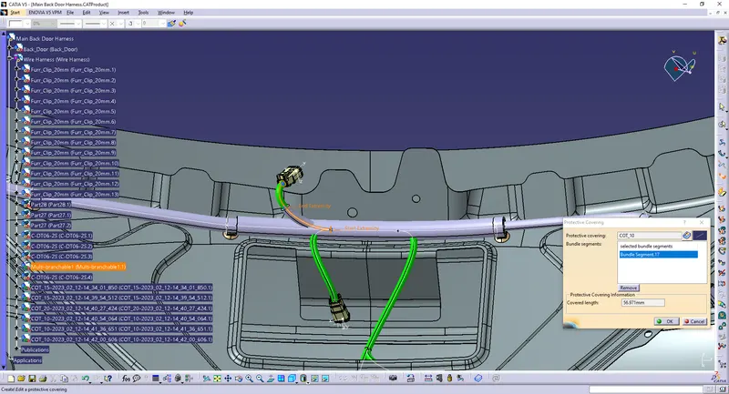
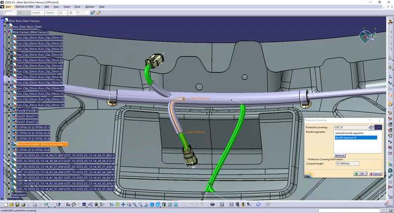
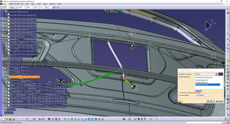
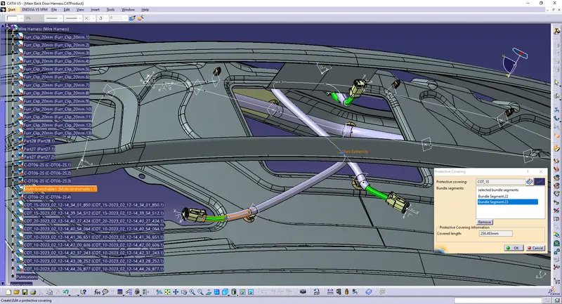
Apply protective covering to the bundle segments:
Keep the extermities 30 mm away from the connectors.

Flattening the Harness Assembly:
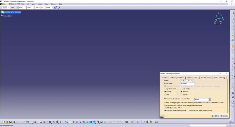
Create a new product and go into the 'Electrical Harness Flattening' Workbench.
Click on the 'Harness Flattening Parameters' option to adjust the parameters.
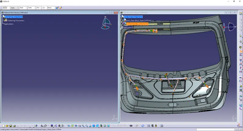
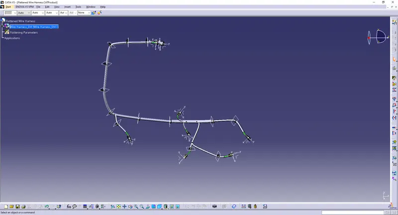
Use the 'Flatten' option to flatten the assembly.
Select a plane/flat surface or a connector and all the the branches.
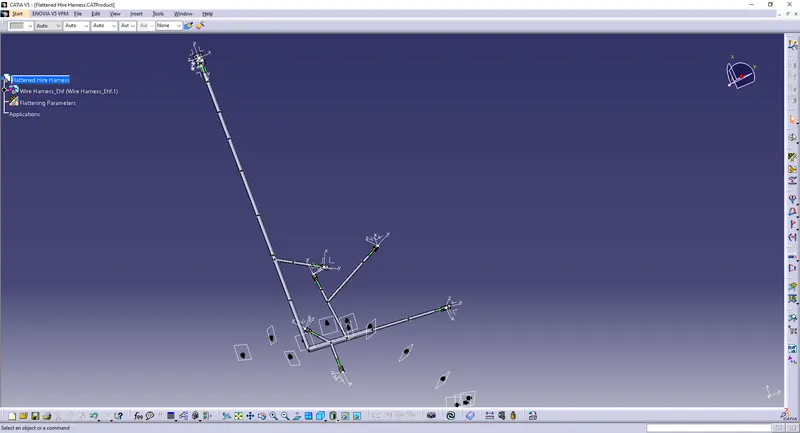
Rotate the bundle segments and align the clips accordingly. use the Manipulation, Smart Move
and Roll option to align.
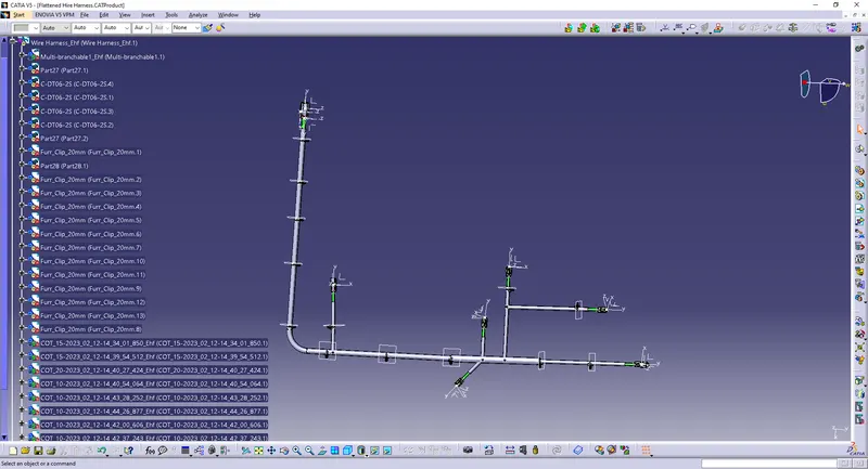
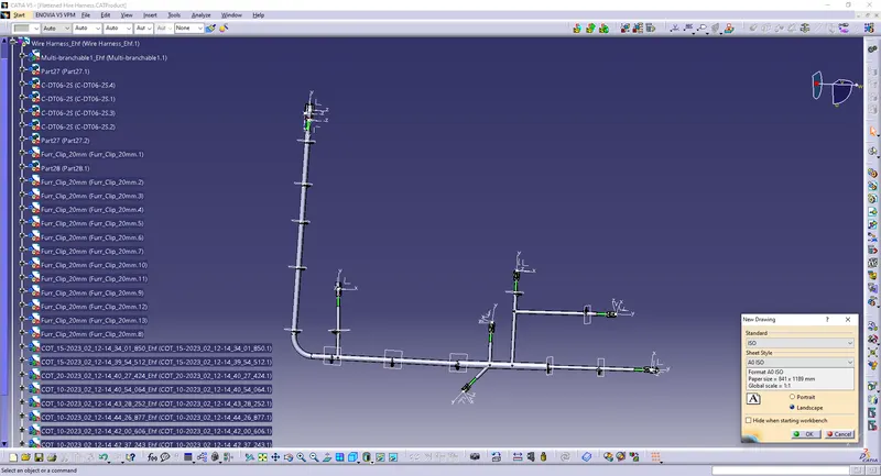
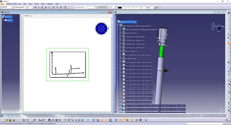
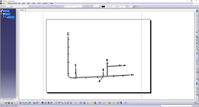
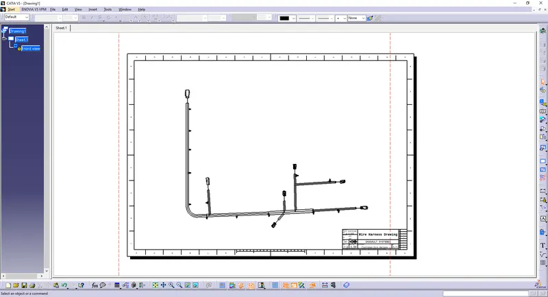
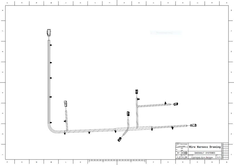
Create a 'Drawing' file and add the harness assembly to the drawing.
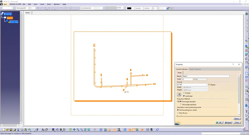
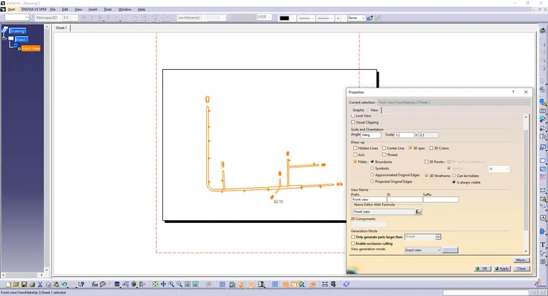
Change the parameters.
Conclusion:
All the necessary properties are applied to the connectors, clip, p-clamp, and cannel.
Provided proper routing of the bundle with support part like clips and clamps.
Added protective covering to the bundles.
Flattened the harness assembly completely. Placed the flattened view on the drawing sheet.