Project 2
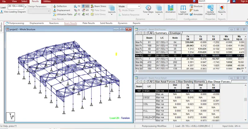
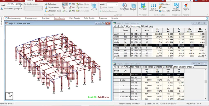
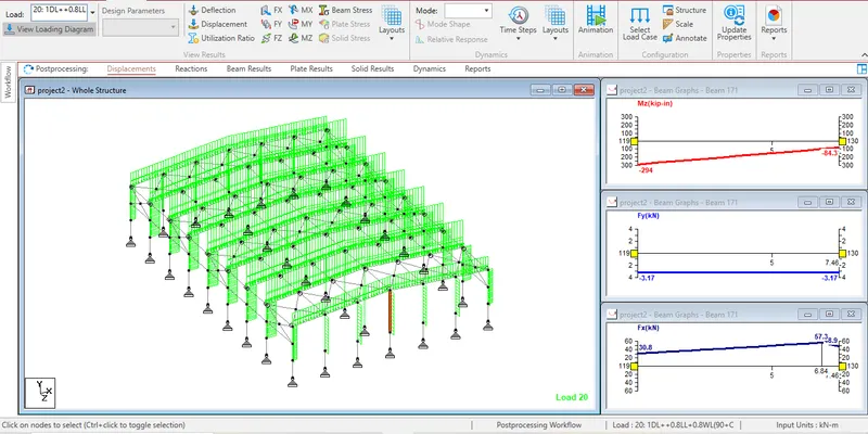
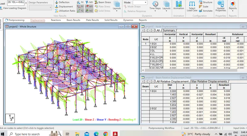
AIM: Design a Warehouse Building located in Chennai using STAAD Pro and staad foundation.
1.1ANS:
GIVEN
|
Width |
30m |
|
Length |
50m |
|
Eave Height |
9m |
|
Bay spacing |
6m |
|
Soil type |
Medium |
|
Safe Bearing Capacity |
200 kN/m2 |
|
Roof slope |
1 in 12 |
STEP_I -Roof Calculation
x/(b/2)=1/12
x/(35/2)=1/12
x=1.46m
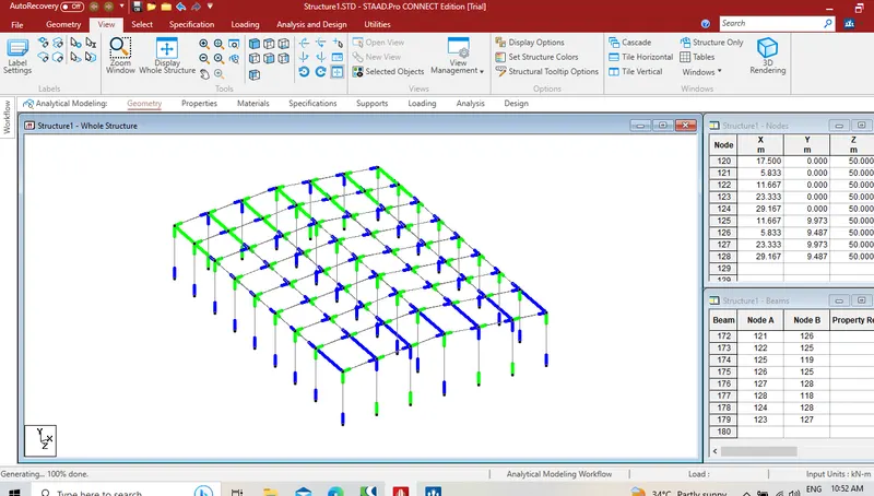
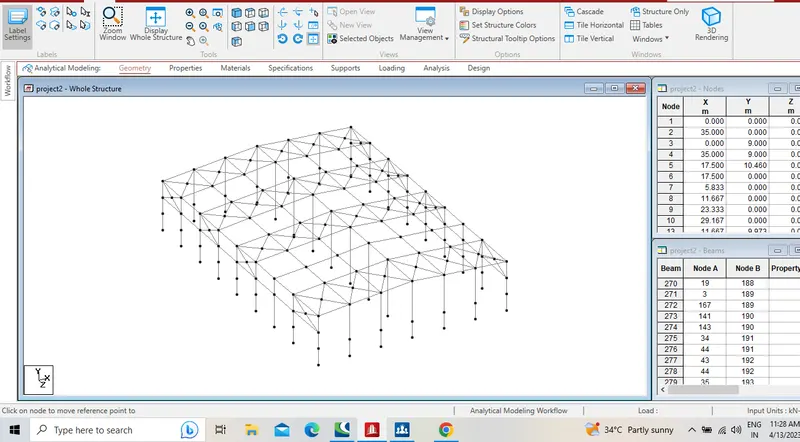
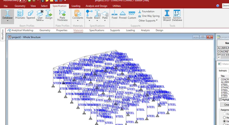
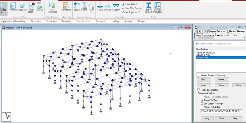
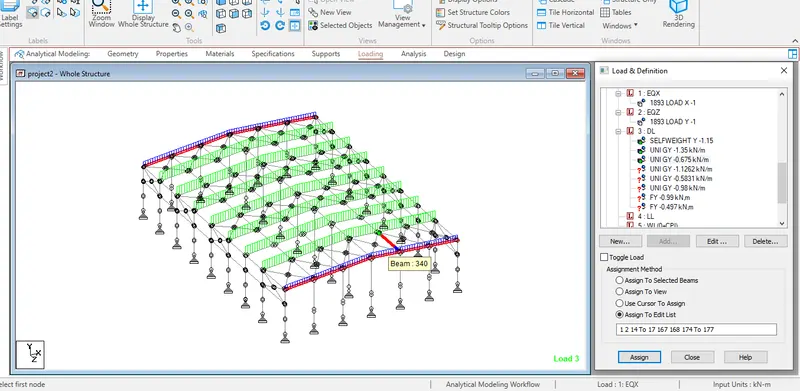
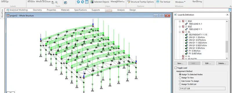
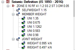
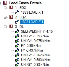

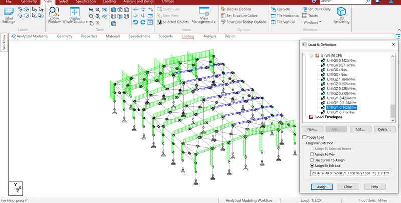
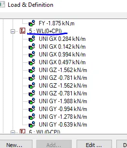
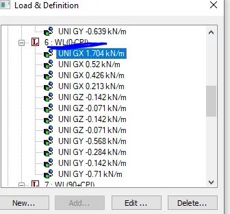
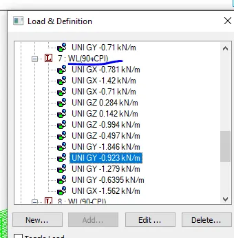
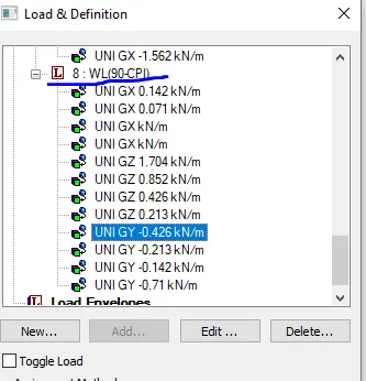
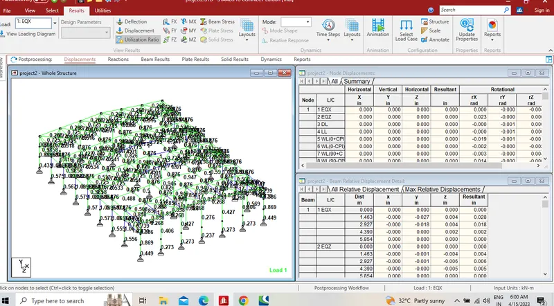
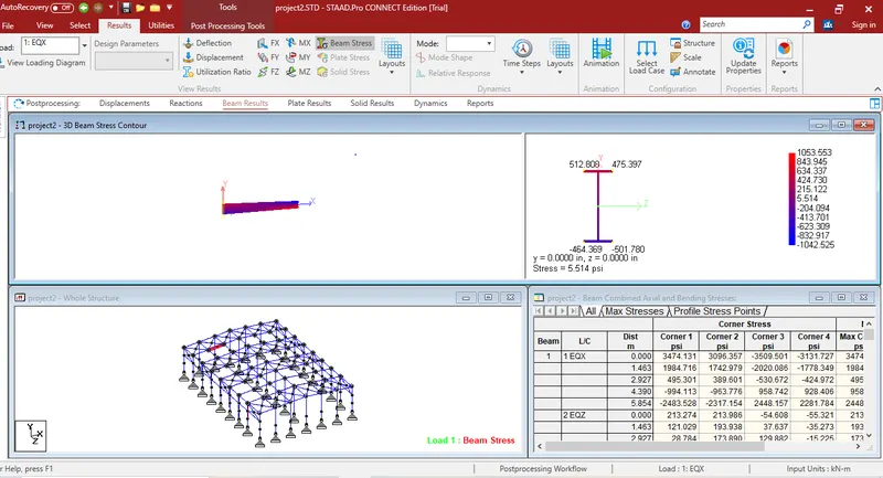
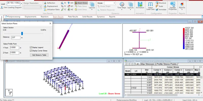
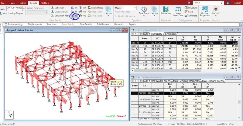
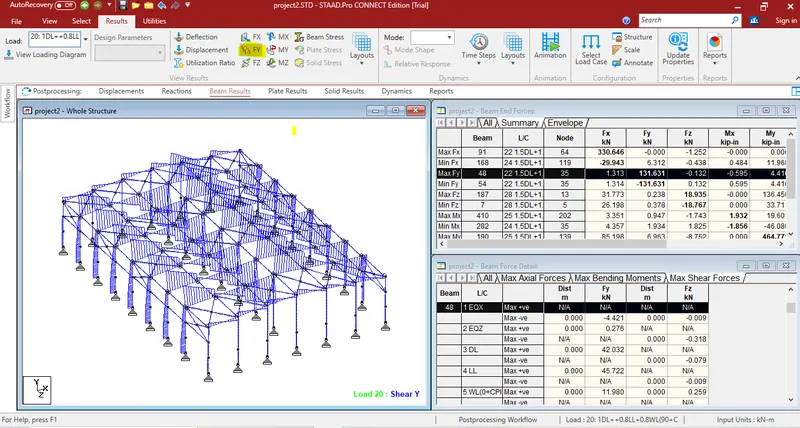
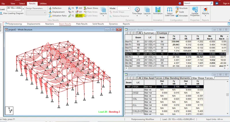
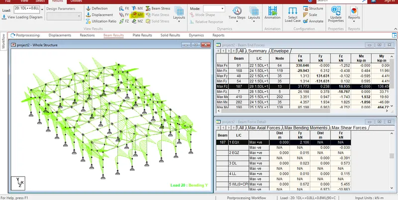
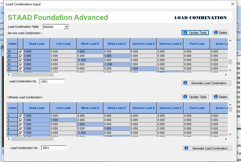
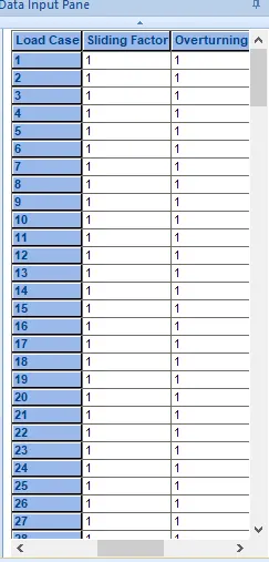
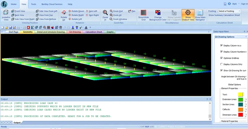
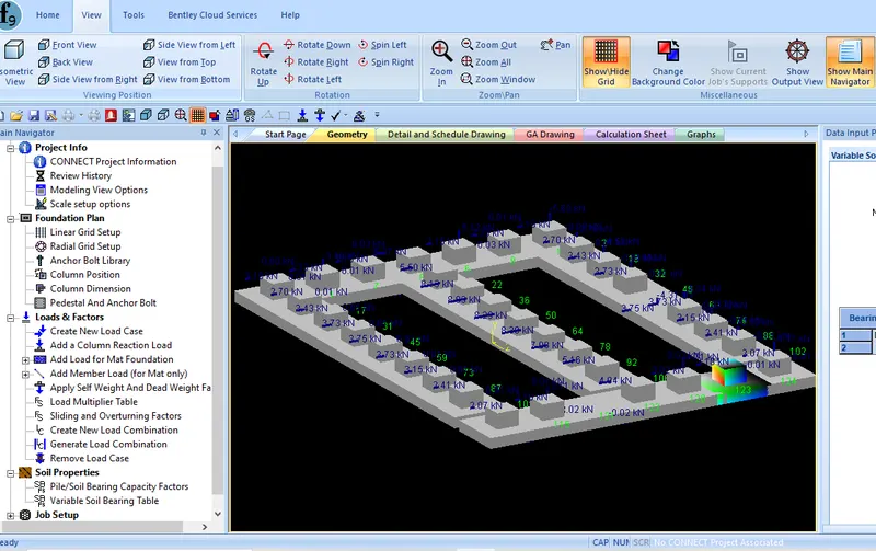
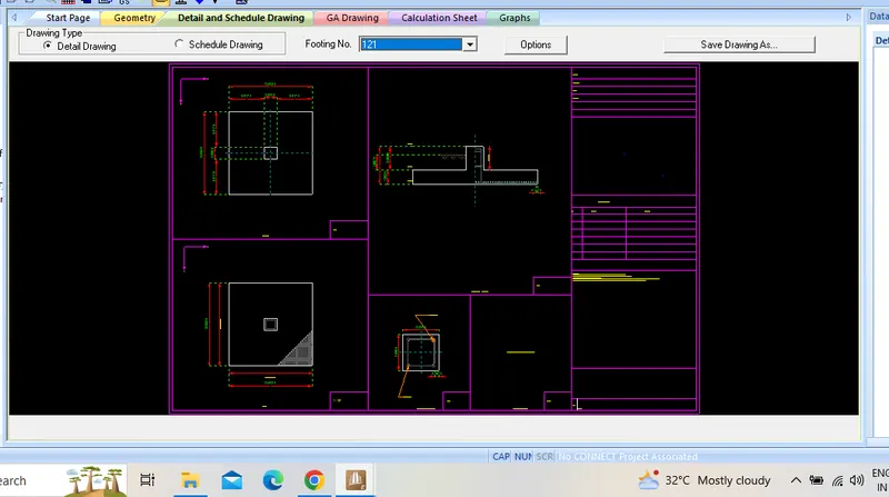
4a ANS:
DESIG OF STEEL COLUMN
Height of the colum = 9 Mts
Reactio of load = 123 KN
Moment = 116 KN
Yield strength = 250 N/mm2
Design compressive strength = 80 N/mm2
STEP-I Required cross section area
Area required =
Design compressive strength(Pd) = Ac*fcd
Ac = Pd/fcd
Ac = 1537 mm2
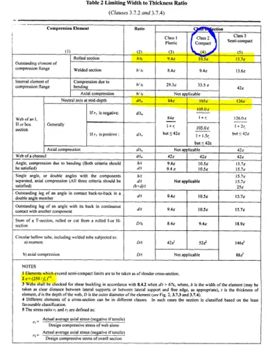
STEP-II Section Classification
Select the section must be greater or equal to Ac=1537mm2
ISMB-300 Section on Is 800- 2007 A-H
A=7485mm2 ry=5.41cm4
B=250mm lyy=2193.6cm4
tw=7.6mm ze=836.3cm3
tf=10.6mm Zp=962.18cm3
h=300mm lxx=12545.2cm4
rx=12.95cm4
Flange criterion = b/tf
11 mm
Web criterion = h/tw
39
€ 1.77
b/tf < 10.50 €
h/tw < 84 €
THIS SECTION IS COMPACT
STEP-III
Axial stress = axial/area
16 N/mm2
Bending stress = Moment(Mu)/section modulus(ze)
138 N/mm2
Horizontal shear developed V = 13 KN
From CI.8.4
Av=h*tw 1900 Vp 274249
Vd=Vp/1.1
Vd = 249317 N
249.317 KN
V/Vd 0.05
V/Vd <0.6
STEP-IV For Unity Check
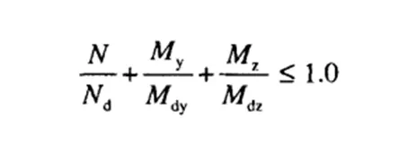
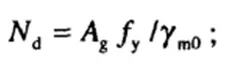
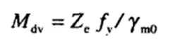
Nd = 1701136
1701.136 KN
Mdv = 190081
1901.81 KN
Therefore
N/Nd+M/Mz <1.0
0.072+0.061<1.0
0.133<1.0
STEP-IV Check for Buckling failure
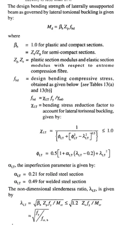
fcr,b from table no 14
h/tf= 23
KL/r= 133 mm
fcr,b= 194.856

תLT 1.135
1.243
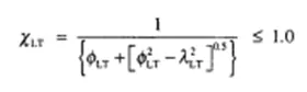
0.6<1.0
fbd =136
4bANS:
DESIGN OF RAFTER
Span of rafter = 5.85 m
Dead load = 0.675 Kn/m
Live load = 2.25 Kn/m
Length of bearing = 100 mm
Yield strength 250 mm2
STEP-I Design load calculation
Factored load = 4.3875 Kn/m
Factored Bending moment = wl2/8 18 Kn-m
STEP-II Section required
Zreq = 1.1*(m/fy)
79200
792 cm3
STEP-III Section Claasification
ISMB-450
Area=92.27mm2 lyy=8340.0cm4 rz=7.5mm
h=250mm rxx=10.15cm Ze=1350.7cm3
b=150mm ryy=3.01cm Zp=1533.36cm3
tf=17.4mm Zxx=1350.7cm3
tw=9.4mm Zyy=111.2cm3
lxx=30390.8cm4 r1=15mm
Flange criterion = b/tf
7 mm
Web criterion = h/tw
47
€ 1
b/tf < 9.40 €
h/tw < 84 €
THIS SECTION IS PLASTIC
STEP-III Moment of resistance of cross section
From CI.8.2
From CI.8.2.1

Md 348490
348.49 KN-M
M<Md
Hence the section is adequte for flexural
STEP-VI Shear resistance of cross section
Shear capacity Vc = 0.6fy Av/1.1 486321
486.321 KN
Factored Shear force V=wl/2 12 Kn
V/Vc 0.025 < 0.6
STEP-V Check for Web buckling
Slenderness ratio of web =2.5d/t = 100 mm
Design compressive stress fcd = 227 N/mm2
Pw= 480105
480.105 kn
>12kn
Hence web is safe against shear buckling
STEP-V Check for Crippling at section
tf+r 32.4 mm
Dispersionn length n2 = 2.5(tfr)
81 mm
Fw = 369869
369.869 kn
>12Kn
Hence section is adequeate for web crippling
STEP-VI Check for Serviceability deflection
Design load = 4.3875 Kn/m
Max deflection = 5wl^4/384EI
0.000334 mm
Allowable deflection = L/200
29 mm
Hence serviceablity is a safe.
4c.ANS:
Design of Base Plate
Step-I
Strength of concrete fcu = 40 N/mm2
Yield strength of steel = 250 N/mm2
Material factor = 1.1 KN
Factored lolad = 600 KN
Step-II Steel column section
The thickness of flange (column) =10.6mm
It must be greater than the column flange
Step-III Area required
Bearing strength of concrete =0.4fcu
16 N/mm2
Area required = load/bbearing strength of concrete
37500 mm2
Let size of base plate B = 150 mm
D = 150 mm
Area of the plate = 22500 mm2
Let the projection on each side a= b = 25 mm
Therefore w W = W = load/area
26 N/mm2
Step-IV Thickness of slab base
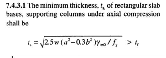
ts = 4.62 mm
< 10.6mm
ts = 11.1884851521553 >tf
So,base plate 150mmx150x11mm
4dANS:
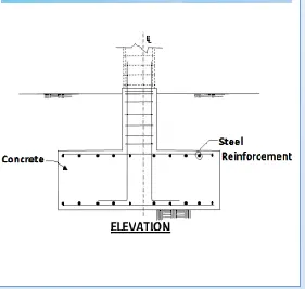
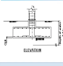
DESIGN OF PEDESTAL
Concrete and Rebar Value Unit
Unit Weight Of Concrete 0.15 kip/ft3
Minimum bar spacing 2 in
Maximum bar spacing 18 in
Strength of concrete 4 kip/in2
Yield strength of steel 60 kip/in2
Minimum bar size 3
Maximum bar size 9
Minimum Ped bar size 3
Maximum Ped bar size 9
Minimum Top bar size 3
Maximum Top bar size 9
Maximum Pedestal Bar Spacing 6 in
Pedestal Tie Bar Size 3
Cover and Soil Value Unit
Soil Type Cohesive Soil
Pedestal Clear Cover 3 in
Bottom Clear Cover 2 in
Unit weight of Soil 0.112 kip/ft3
Soil bearing capacity 0.017 kip/in2
Soil Bearing Capacity Factor For Ultimate Loads 1.7
Soil Depth 20 in
Type of Depth Fixed Top
Surcharge for loading 0 kip/in2
Depth of Water Table 78.7 in
Cohesion 0 kip/in2
Shear Strength 0 kip/in2
Phi value of soil (in Degree) 0
Min. % of Contact Area 0
Minimum % of Contact Area For Ultimate Loads 0
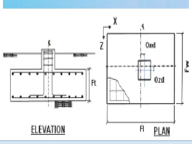
Footing Geometry Value Unit
Footing Type Uniform Thickness
Design Type Calculate Dimension
Calculate Dimension Type User Specific minimum dimensions
Minimum Length =100 in
Minimum Width =100 in
Minimum Thickness =19 in
Minimum Slope End Thickness =10 in
Maximum Length =300 in
Maximum Width=300 in
Maximum Thickness =28 in
Maximum Slope End Thickness =100 in
Plan Dimension Inc. =2 in
Thickness Increment= 2 in
Offset X direction 0 in
Offset Z direction 0 in
Length/Width Ratio 1
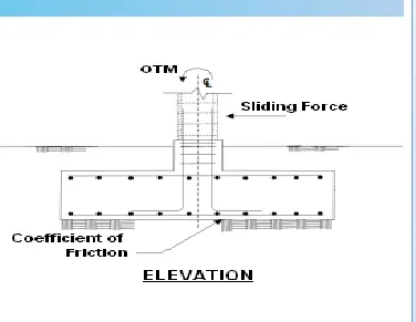
Sliding and Overturning Value Unit
Coefficient of friction =0.5
Factor of safety against sliding= 1.5
Factor of safety against overturning= 1.5
Consider Passive Earth Pressure No
Consider Cohesion Effect No
4eANS:
Design of Purlins
Step-I
Yield stress for the steel,fy = 250 N/mm2
Elastic Modulus of steel,Es = 2*10^5 N/mm2
Partial safety factor for material = 1.1
Slope of roof ,θ = 6
Effective length of the purlin@Lz = 6 m
Effective length of the purlin@Ly = 3 m(sag rods)
Maximum c/c spacing of purlins,s = 1.5 m
Step-II Section propreties
Let Purlin section ISMC125
A = 16.19 cm2 lyy = 59.9 cm4
h = 125 mm rxx = 5.07 cm
bf = 65 mm ryy = 1.92 cm
tf = 8.1 mm Zxx = 66.6 cm3
tw = 5 mm Zyy = 13.1 cm3
cyy = 1.94 cm r1 = 9.5 mm
lxx = 416.4 cm4 r2 = 5 mm
λxx = KL/rxx 118 <300
λyy = KL/ryy 156 <300
Design shear strength Vd@ major axis = 82 KN
Design shear strength Vd@ minor axis = 138 KN
Step-III Forces &Moments
Load case 1- Dead load
Weight of sheeting = 0.08 KN/m2
Other load(insulation,sag rods, etc) = 0.005 KN/m2
Total dead load = 0.085 KN/m2
Udl on purlin due to DL = 0.1275 KN/m
Self wt of purlin from ismc125 = 0.127 KN/m
Total udl = 0.2545 KN/m
Load case 2- Live load
Total Live load = 0.75 KN/m2
Udl on purlin due to DL = 1.125 KN/m
Load case 2- Wind load
Maximum upward wind pressure = 0.8 KN/m2
Udl on purlin due to Max U/w WP = 1.2 KN/m
Maximum downward wind pressure = 0.5 KN/m2
Udl on purlin due to Max D/w WP = 0.75 KN/m
Step-IV Load combination1-DL+LL
Factored udl on purlin due to DL+LL = 2.06925 KN/m
Load on purlin DL+LL = 0.835 KN/m2
Shear major axis force,Vz = 6 KN
Shear minor axis force,Vy = 0.62 KN
Bending moment at major axis force,Mz = 9.27 KN-m
Bending moment at minor axis force,My = 0.23 KN-m
Check for stress
fbc = (Mz/Zz)+(My/Zy) 156.7464411 N/mm2
Permissible bending stress for the section = 227 N/mm2 >156.75N/mm2
Hence stress is ok
Utilization ratio = 156.75/227
0.69
Check for Deflection
Deflection at major axis = 5wl^4/384 EI 27.81 mm
27.81mm < L/150 40 mm
Hence Ok
Deflection at minor axis = 5wl^4/384 EI 0.64 mm
0.64mm < L/150 20 mm
Hence Ok
Step-V Load combination2-DL+WL(Upward Wind Pressure)
Factored udl on purlin due to DL+WL = -1.572 KN/m
Load on purlin DL+LL = 0.885 KN/m2
Shear major axis force,Vz = 4.720 KN
Shear minor axis force,Vy = 0.07 KN
Bending moment at major axis force,Mz = 7.07 KN-m
Bending moment at minor axis force,My = 0.03 KN-m
Check for stress
fbc = (Mz/Zz)+(My/Zy) 123.7134081 N/mm2
Permissible bending stress for the section = 227 N/mm2 123.713
Hence stress is ok
Utilization ratio = 123.713/227
0.55
Check for Deflection
Deflection at major axis = 5wl^4/384 EI 19.18 mm
19.18mm < L/150 40 mm
Hence Ok
Deflection at minor axis = 5wl^4/384 EI 0.22 mm
0.22mm < L/150 20 mm
Hence Ok
Step-VI Load combination2-DL+WL(Downward Wind Pressure)
Factored udl on purlin due to DL+WL = 1.50675 KN/m
Load on purlin DL+LL = 0.585 KN/m2
Shear major axis force,Vz = 4.520 KN
Shear minor axis force,Vy = 0.11 KN
Bending moment at major axis force,Mz = 6.77 KN-m
Bending moment at minor axis force,My = 0.04 KN-m
Check for stress
fbc = (Mz/Zz)+(My/Zy) 104.7050868 N/mm2
Permissible bending stress for the section = 227 N/mm2 >104.751
Hence stress is ok
Utilization ratio = 104.751/227
0.46
Check for Deflection
Deflection at major axis = 5wl^4/384 EI 20.33 mm
20.33mm < L/150 40 mm
Hence Ok
Deflection at minor axis = 5wl^4/384 EI 0.22 mm
0.22mm < L/150 20 mm
Hence Ok
Step-Vii Load combination2-DL+WL+LL(Downward Wind Pressure)
Factored udl on purlin due to DL+WL+LL = 2.1054 KN/m
Load on purlin DL+LL = 1.335 KN/m2
Shear major axis force,Vz = 6.300 KN
Shear minor axis force,Vy = 0.50 KN
Bending moment at major axis force,Mz = 9.47 KN-m
Bending moment at minor axis force,My = 0.19 KN-m
Check for stress
fbc = (Mz/Zz)+(My/Zy) 156.696009 N/mm2
Permissible bending stress for the section = 227 N/mm2 >156.696
Hence stress is ok
Utilization ratio = 156.696/227
0.69
Check for Deflection
Deflection at major axis = 5wl^4/384 EI 34.41 mm
34.41mm < L/150 40 mm
Hence Ok
Deflection at minor axis = 5wl^4/384 EI 0.22 mm
0.97mm < L/150 20 mm
Hence Ok
2ANS:
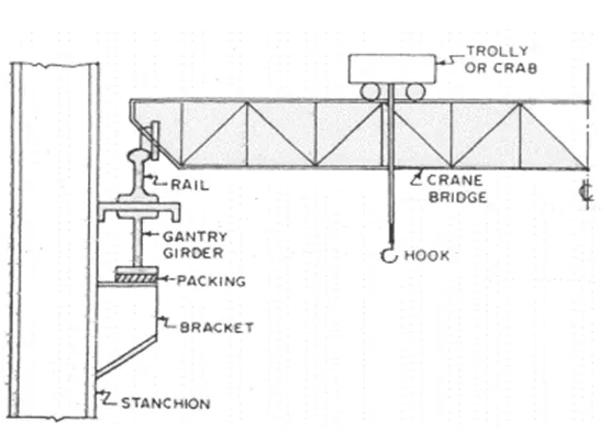
Step 1
Span of gantry girder = 7 m
Span of crane girder = 9 m
Crane capacity = 250 kN
Self weight (trolley,hook,motor) = 40 kN
Self weight of crane girder = 100 kN
Minimum hook approach = 1 m
Distance between wheels = 3 m
Self weight of rails = 0.2 kN/m
Step 2 Maximum moment due to vertical load
Weight of trolley + Weight of load lifted = 140 kN
Self weight of crane girder = 100 kN
For maximum reaction on girder, the moving load should be as close to the gantry as possible
200 kN
Reaction at A RA = 190 kN
Load on gantry girder from each wheel = 95 kN
Factored wheel load = 142.5 kN
RD = 106.875 kN
Maximum moment ME = 240.47 kNm
let self weight of girder = 2 kN/m
Dead load (self weight + rails) = 2.2 kN/m
Factored DL = 3.30 kN/m
M due to DL = 20.21 kNm
M due to impact load = 60.12 kNm
Factored moment due to all vertical loads
M = 320.80 kNm
Step 3 Maximum moment due to lateral load
Hzl. Force transferred to rails = 14 kN
Horizontal force on each wheel = 3.5 kN
Factored horizontal force = 5.25 kN
Maximum moment = 8.86 kNm
Vertical shear due to
wheel loads = 213.75 kN
impact = 53.44 kN
self weight = 9.90 kN
Total shear = 277.09 kN
Lateral shear due to surge = 10.21 kN
Step 4 Preliminary section determination
Minimum economic depth D = L/12
= 583.3333333 mm
Width of compression flange b = L/40 to L/30
= 175 233
Required plastic modulus Zp = 1.4 x M / fy
= 1796471.25
= 1796.47 x103 mm3
Let us try ISMB 600 with ISMC 400 on compression flange
Step 5 Properties of selected section
ISMB 600 @ 1.21 kN/m ISMC 400 @ 0.49 kN/m
A 15600 mm2 A 6380 mm2
h 600 mm h 400 mm
b 210 mm b 100 mm
tf 20.3 mm tf 15.3 mm
tw 12 mm tw 8.8 mm
Izz 91800 x104mm4 Izz 15200 x104mm4
Iyy 2650 x104mm4 Iyy 508 x104mm4
R 20 mm Cyy 2.42 mm
Step 6 Determination of section modulus
Let the distance of N.A from the tension range by y'
y' = 388.93 mm
Izz = 1348.128426 x106mm4
Zez = 3466240.196 mm3
For compression flange about y-y axis
I = 16766.6525 x104mm4
Zey = 838332.625 mm3
Total area of section = 21980 mm2
Let plastic NA be at a distance Yp from tension flange.
Yp = 580.88 mm
Zpz = 4410317.327 mm3
For top flange Zpy = 1078488.402 mm3
Step 7 Section classification
For ISMB b/t = 4.90
< 9.4e
d/t = 43.28
< 84e
For ISMC b/t = 5.96
< 9.4e
Hence section is plastic
Step 8 Check for local moment capacity
Local moment capacity for bending in vertical plane
Mdz = fyZp / 1.1
= 1002.34 kNm
= 1.2 Zefy / 1.1
= 945.34 kNm
Mdz = 945.34 kNm
For top flange
Mdy = 245.11 kNm
= 228.6361705 kNm
Mdy = 228.64 kNm
Step 9 Check for combined local capacity
0.38 < 1
unity check
Step 10 Check for buckling resistance
Md = βb Zp fbd
For plastic section βb = 1
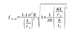
LLT = 7000 mm
E = 200000 N/mm2
hf = 597.5 mm
Iy = 17850 x104mm4
A = 21980 mm2
ry = 90.12 mm
fcr,b = 417.43 N/mm2
λ = 0.774
ϕ = 0.95
X = 0.97 N/mm2
fbd = 166.5909091
Mdz = 734.72 kNm
Mdy = 202.84 kNm
Hence 0.48 < 1
Hence section is safe against torsional buckling
Step 11 Check for shear
Vz = 277.09 kN
Shear capacity = Av*fyw / √3 *1.1
= 944754.9859 N
= 944.7549859 kN
> 277.09
Now = 566.8529916 kN
low shear
Step 12 Check for web buckling
b = 175 mm
n1 = 232.6 mm
d = 519.4 mm
t = 12 mm
λ = 104.7456667
For buckling Class a Table 9a
Fcd = 128.6 N/mm2
Buckling resistance = 629008 kN
> 277.09 kN
Step 13 Check for deflection at working load
Serviceability vertical wheel load = 95 kN
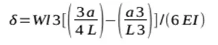
Deflection at mid span
a = 2000 mm
Izz = 1348.13 x106mm4
δ = 9.60 mm
Horizontal deflection
I = 16766.65 x104mm4
δ = 4.88 mm
L/750 = 9.33 mm
Unsafe in vertical direction
Safe in lateral direction
RESULT:To complete the design of ware house in staad pro.