Project 2
AIM
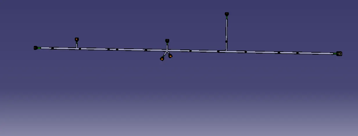
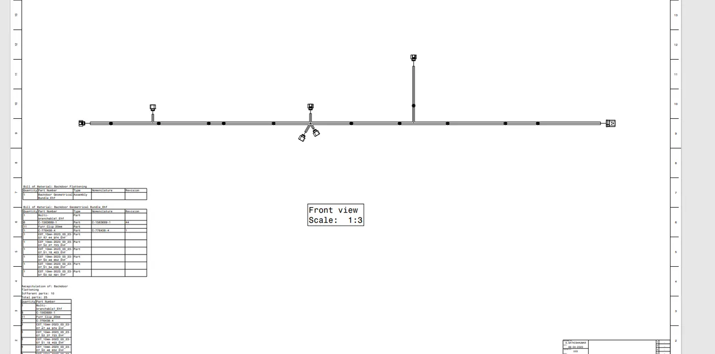
Route the wire harness on back door and prepare flatten drawing using CATIA V5
OBJECTIVE
Route the wire harness for car back door
prepare flatten view drawing in CATIA V5
Apply all packaging rules and industrial best price
Apply protection covering as required
Packaging rules and assumption made in the project
Avoid harness routing and clipping in blind zone
Provide additional slack to the according to surroundings
Provide enough clearance for the wire harness
Provide guiding channel if required
Enough clamps to be provided to ensure positive clearance with surrounding
Distance between two clamp in same branch to 200 mm
Use rubber grommet for protection and vibration
Branch length should be minimum 50 mm
Minimum distance between clip and branch point should be 23 mm
Maximum branches on a single point should be 4
TECHNICAL SPECIFICATIONS AND ASSUMPTIONS:
Wiring harness routing shall be ease in manufacturing, accessibility, maintenance and removal.
Avoid routing through small structural holes, bolts, bolted joints, screwed joints to avoid harness puncture
Provide additional slack to the harness according to the surrounding and harness bending requirements.
Provide additional slack to the harness branch which connects to the loads and covered with enclosures.
Avoid routing near sharp edges or over the sharp edges, in case of non avoidable situations additional protection should be provided.
Ensure harness is routed atleast 100mm away from ABC pedals.
Enough clips and clamps shall be provided to ensure the positive clearance with surroundings and safety of wiring harness.
Keep the harness away from engine heat generation components, heating lines and EGR components.
Avoid direct support of harness on fuel lines routed in engine, in that case a separator clamp to be provided to satisfy clearance requirements.
Harness branch length should minimum 50mm.
Minimum distance between clip and nearest branching point should be 25mm.
Limit the number of branches from single branching point to 4.
Harness Protection should be provided according to the surrounding temperature.
Clips/Clamps that are used should be selected such that they are easily available in the market.
The given car body hatch focuses on different areas of study under which comprises of routing harness bundles for two tail lamps and two number plate lights which connects the car main electrical system.
For all these four lights a Deustch 2 pole connectors are used (DT06-2s) and a an Interconnection connector which connects from car body hatch to the main car body wiring harness and is used at a preferred location from where the routing for these lights starts. For interconnection 12 pole connector is used.
As for the mounting parts clips/clamps which are used where ever necessary, hellerman mounting clip and fixing clips are used.
PROCEDURE:
DOWNLOADED BACKDOOR FILE
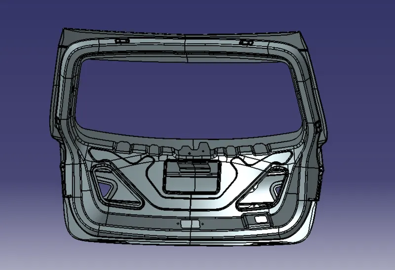
Step1: Creating Car body context assembly and Geometrical assembly
Car body hatch context assembly contains 3D data of car body hatch and all the non electrical data are stored in it and also the geometrical bundle assembly which consists of the electrical data needed for the project.
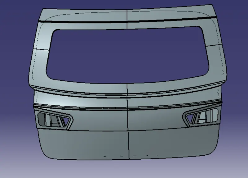
Step2: Defining 12 pole inter connector electrically and position it.
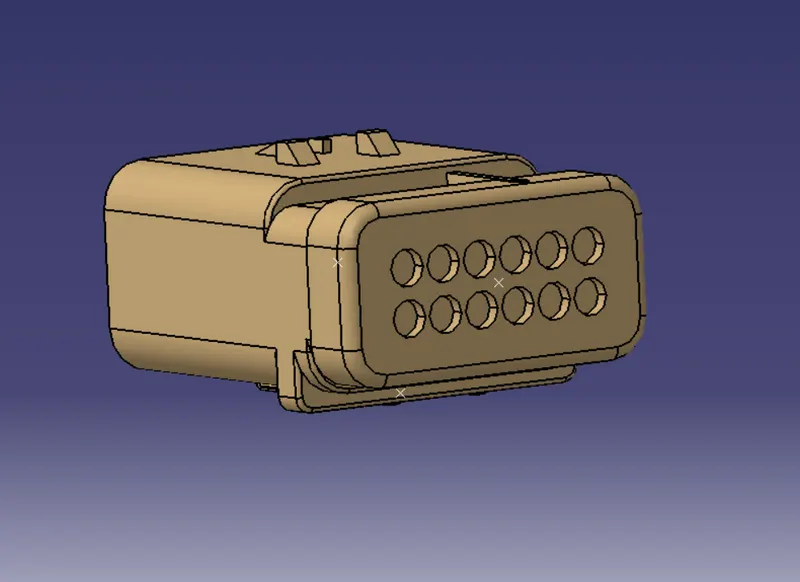
Step3: Defining 2 pole connector electrically.
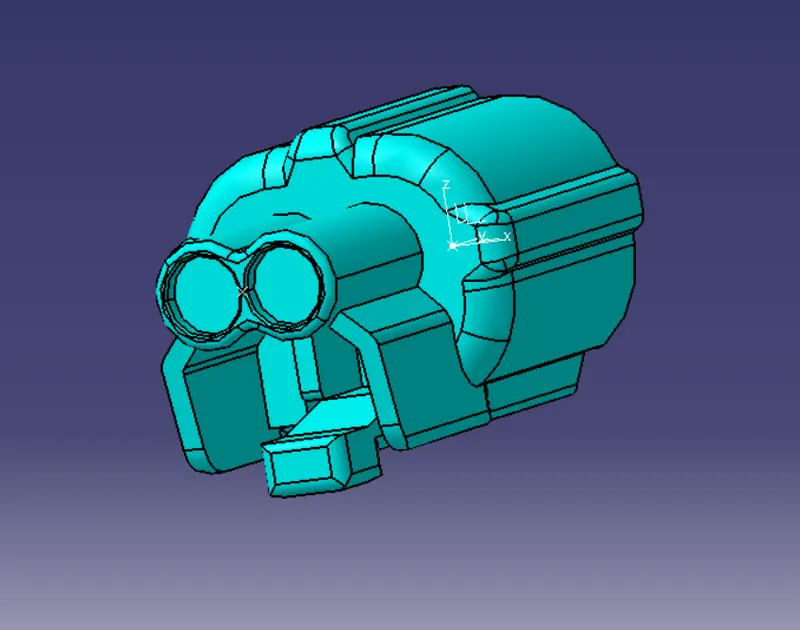
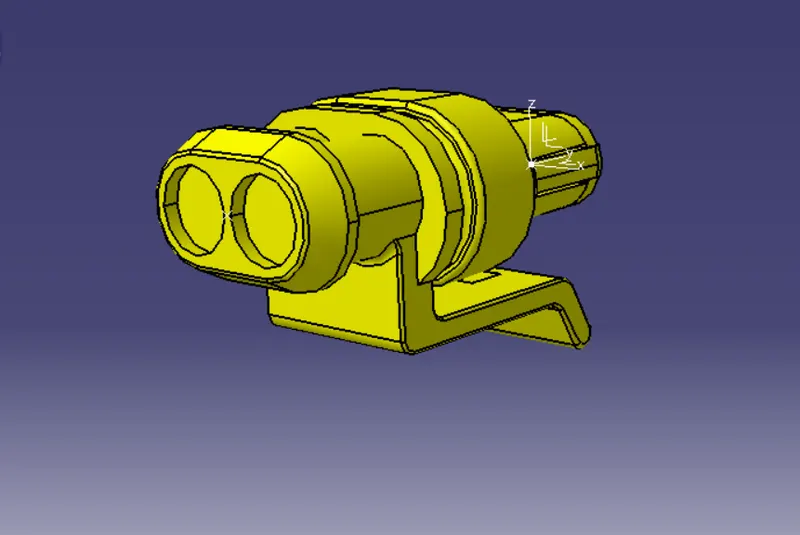
The 2 pole connector DT06-2S is used as 2 for lights, 1 for number plate, 1 for wiper motor, 1 for rear camera, 1 for rear sensor are defined electrically with all the bundle connection point and connector connection points, as shown in the fig below.Then position it at the appropriate place.
Step 4: Defining Clips as support
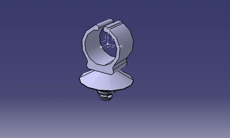
Step 5:Positioning the Defined Clips as support
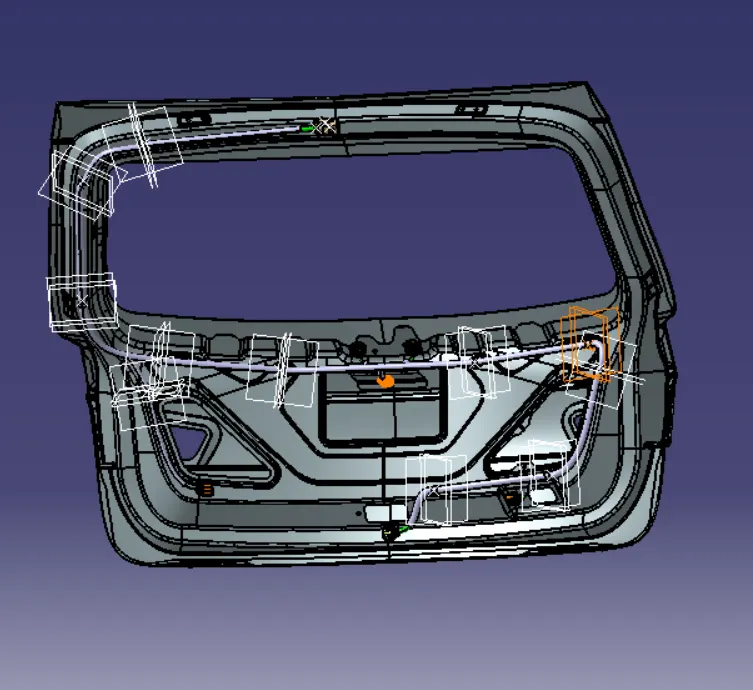
Step 6: Bundle routing from interconnection connector to all the connectors arranged and all the mounting clips
The dimensions assigned for bundles, like diameter and bend radius are assumed and actual values are provided at a later stage. From the below figure it is seen that the routing starts from the interconnection connector and goes through all the clips and then to the all the connectors.
The bend radius for all the bundles is assumed to be 1.4mm
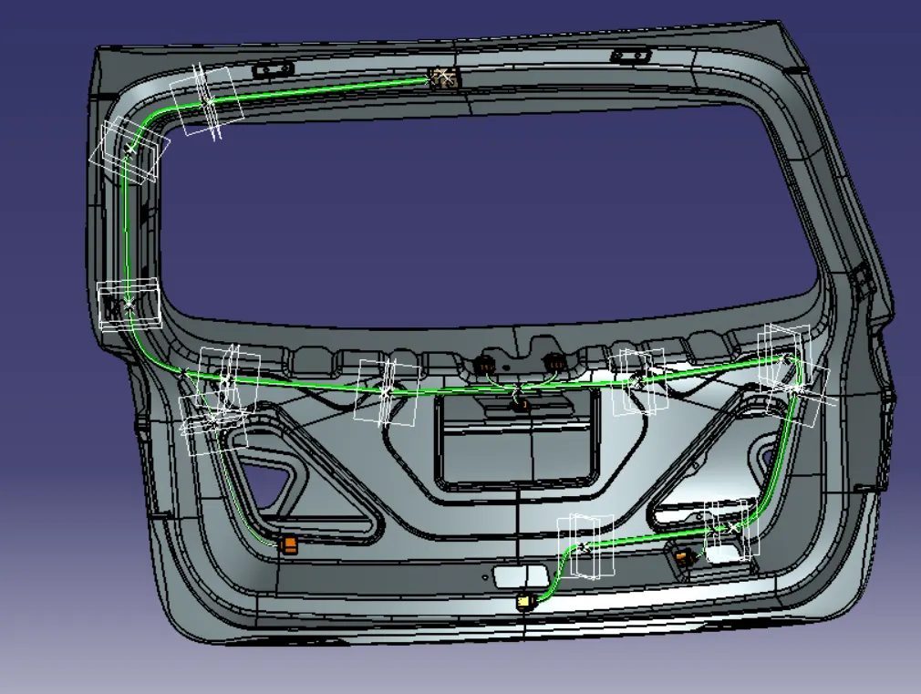
Step 7: Creation of protection covering(COT Tubes) for the routing
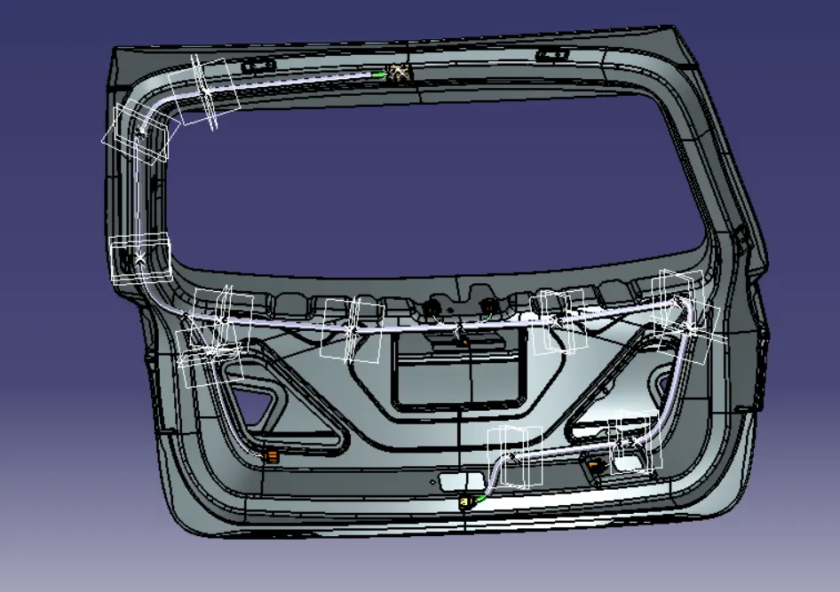
Step 8: Creation of Flattening for the routing