Project 2
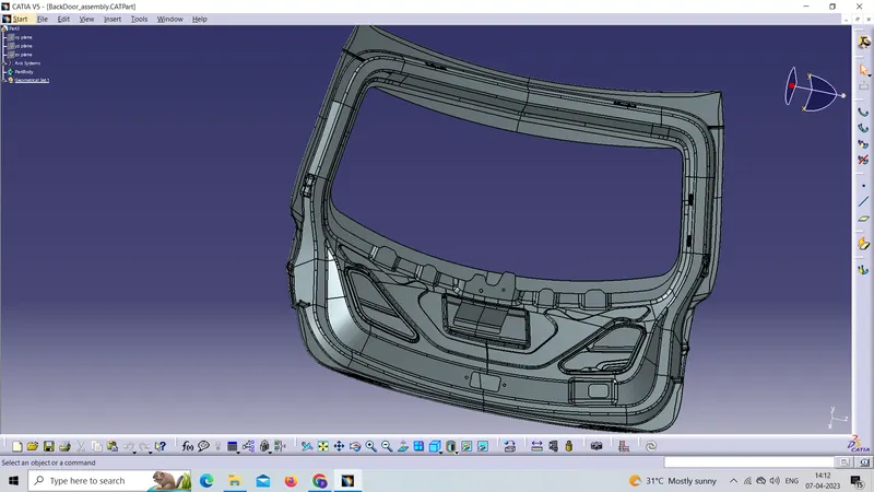
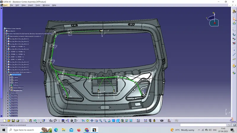
Above picture is the Backdoor of a car for which a Wiring Harness has to be designed
A wiring harness will be done for the taillights and the no-plate lights
There are 3 Taillight connectors which have 4 poles and 2 numberplate light connectors which have 2 poles and a 12-pin Interconnection connector
The Interconnection connector that will connect it to the Main Harness
The bend ratio should be 1.5 for all bundle segments.
Step 1:
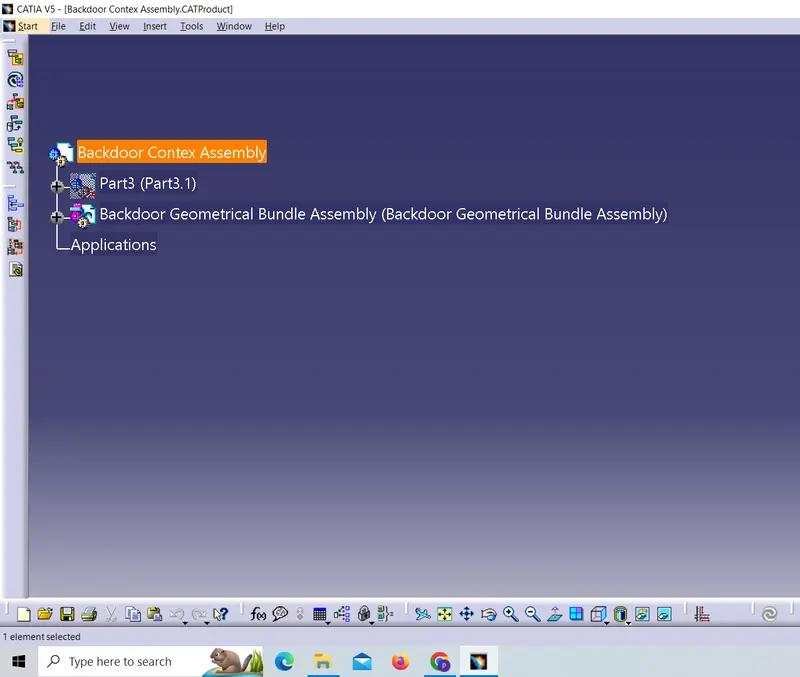
Creating the context assembly and Then adding the Given car body And also creating the geometrical bundle assembly in which we can route the Wiring harness
Step 2:
define the electrical properties of the components (Different connectors And supporting devices ) which are used for routing the wiring harness
1. ‘C-776438’ Which is a 12 Pole connector is used as an Interconnection Connector
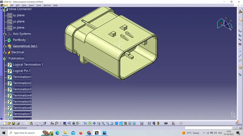
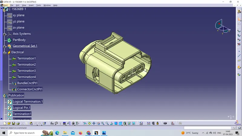
2. 'C-1563689-1' is a Taillight connector that has 4 poles
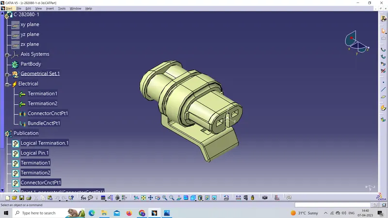
3. 'C-282080-1' numberplate light connector which has 2 poles
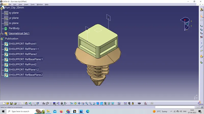
4. fir tree clip is used for supporting the bundle segments
Step 3
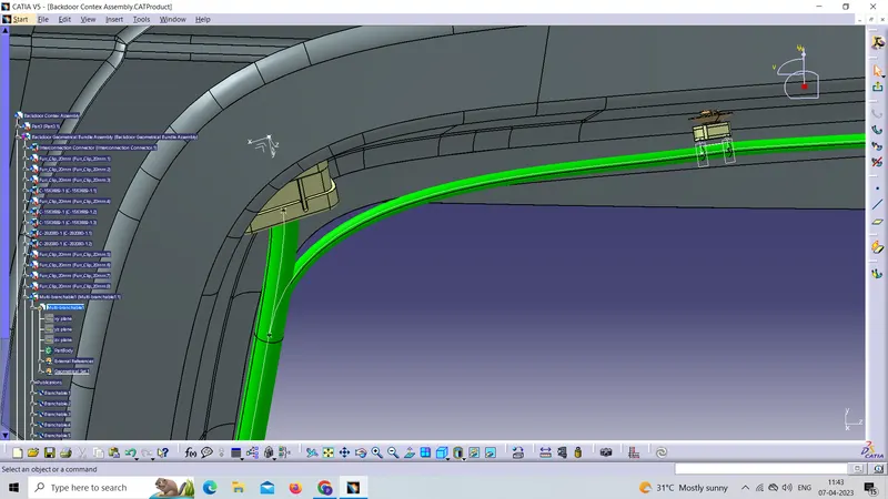
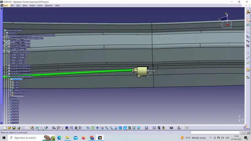
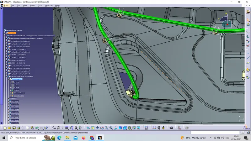
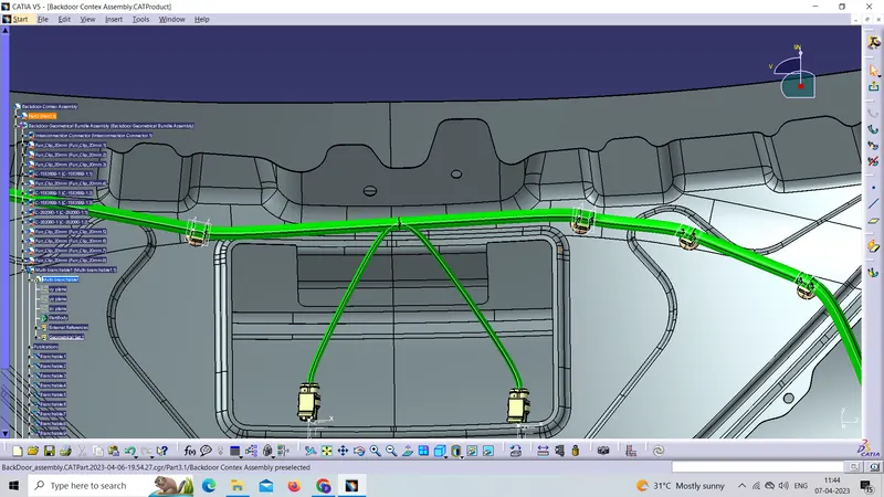
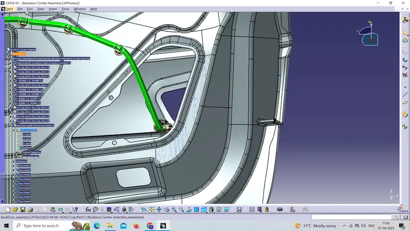
Now placing the connectors Clips in the required places for routing the wiring harness
Step 4:
Bundle Routing
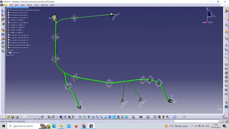
The bundle segment is routed from the interconnection connector to the fir tree clip and guided towards the 4 and 2 Pin connectors. while maintaining the Bend radius ratio of 1.5.
We have used bundle thickness of 5-10mm
Step 5:
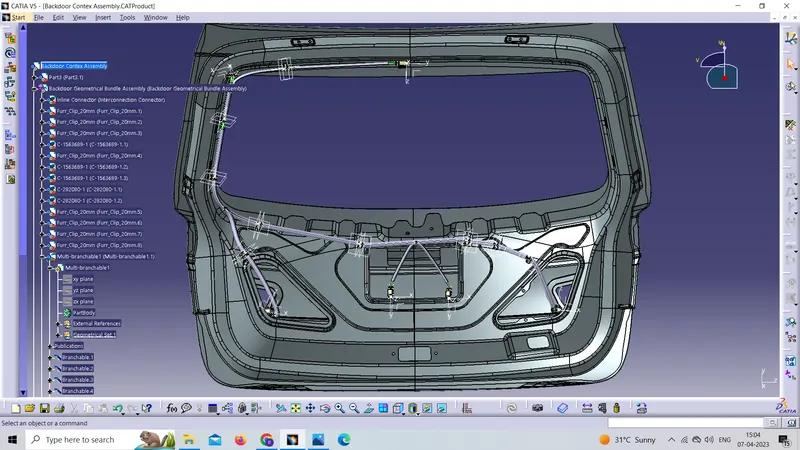
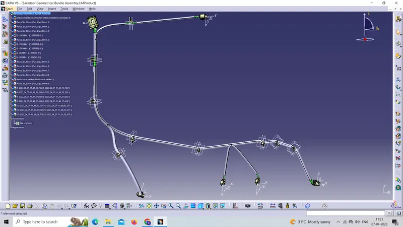
Adding protective coverings to harness the bundle
Here is the below figure, we have done with the whole wiring harness routing for the Backdoor. Now, we have to add protective coverings to all bundle segments
Step 6:
Checking the bundle continuity
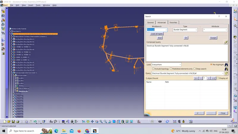
In this step, we must first ensure that multi-branch capability is selected before proceeding to Edit>Search>Advanced>Workbench-Electrical>Type-Bundle Segment>Attribute-Fully Connected.
Selecting 'True' displays all connected bundle segments while selecting 'False' displays all non-connected bundle segments.
In this case, we chose the 'True' option and searched for results. As shown in the figure below, all of the bundle segments are highlighted, indicating that they are all electrically connected.
Step 7:
Creating a flattened view of the Backdoor Wire harness geometrical bundle assembly
In this step, we will use Catia V5's Electrical Harness Flattening workbench to create a flattened view. We should also ensure that the flattening file is saved in the same folder as the other harness assembly files.
The bundle assembly was extracted into a Back door wire Harness Flattening the Product file, now by using flattening commands we flatten the wiring harness shown below picture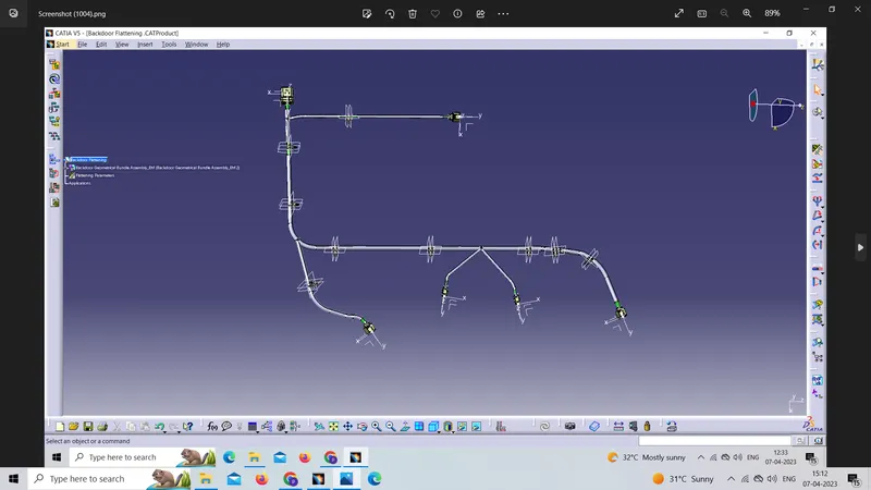
step 8:
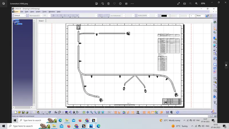
here I created a drawing view of a flattened wiring harness
for creating drawings we create a new drawing file after creating the drawing file click on the front view command and go back to the file which we have drawn in drawing view and click on any surface we want from the drawing representation