Project 2
Q . Using MATLAB/simulink and the drive cycle from the attached excel sheet, find-
- The max heat generation of the battery
There are two types heat sources for battery generation
i. Joules heat
ii. Entropy heat
Heat genrated = Joules Heat + Entropy Heat
Joules Heat = i^2Rt
get form Ohm Law
V= IR
when a current flowing through a resistance there is a heat dissipited in the resistor , This heat dissipation is called Joule heating. Joule heating is also known as ohmic heating.
Power,
P= V*I = I*I*R = I^2R
Heat , H = ∫P.dt with time limit ) to t
H= I^2*R*t
Joule heat
H = I^2*R*t
where
p = Power
V = Voltage
R = Resistance
H= Heat
t = Time
Entropy Heat
The heat generation due to entropy change inside a battery occurs when electro chemical reactions are performed. The entropy heat is reversible heat resulting from change in open circuit voltage with respect to temperature at two Electronics
Entropic heating Coefficieny -
it is the rate of change of the batteries open circuit voltage wrt to temp
it is a function of temperature and SOC
it is often expressed in V/k
Heat generated = joule heat + Entropy Heat
Maximum Heat genrated = Max Joule +2
=Imax^2*R*maxTime+2
= (-0896)^2*2*2sec+2
= 3.21126+2
= 5.21126 JOULE
2. The SOC of the battery at 2 *104second of the battery operation
| Time | Time Step | Battery Current |
| 00:00.4 | 0.1 | -0.9632 |
| 00:00.5 | 0.2 | -0.952 |
| 00:00.6 | 0.3 | -0.9072 |
| 00:00.7 | 0.4 | -0.9632 |
| 00:00.8 | 0.5 | -1.0304 |
| 00:00.9 | 0.6 | -0.9632 |
| 00:01.0 | 0.7 | -1.0304 |
| 00:01.1 | 0.8 | -1.008 |
| 00:01.2 | 0.9 | -0.9856 |
| 00:01.3 | 1 | -0.9632 |
| 00:01.4 | 1.1 | -0.9184 |
| 00:01.5 | 1.2 | -0.9296 |
| 00:01.6 | 1.3 | -0.9296 |
| 00:01.7 | 1.4 | -0.9296 |
| 00:01.8 | 1.5 | -0.9184 |
| 00:01.9 | 1.6 | -0.9408 |
| 00:02.0 | 1.7 | -0.896 |
| 00:02.1 | 1.8 | -0.9072 |
| 00:02.2 | 1.9 | -0.9072 |
| 00:02.3 | 2 | -0.9408 |
| 00:02.4 | 2.1 | -0.9296 |
| 00:02.5 | 2.2 | -0.9296 |
| 00:02.6 | 2.3 | -0.9968 |
| 00:02.7 | 2.4 | -0.9968 |
| 00:02.8 | 2.5 | -0.9408 |
| 00:02.9 | 2.6 | -0.9408 |
| Battery resistance | 2 milli ohm |
Consider the battery resistance is 0.5 mOhm, delta time is 0.1 and entropic factor is 2
The SOC refers to the state of charge of the battery , which is capcity percent left in the battery which can be used. (For Battery Status)
The SOC can be measured in different way . Some of them are listed below
1. Voltage Trsnalation Method (VT)
2. Coulamb Counting method (CC)
3. Combination of VT and CC
it is measured by Open Circuit Voltage of the battery and comapred it with the Data SHeet of the battery and SoC is edtimated it cannot used while battery is in operation
CC -
it is calculated by the formula
SoC = Total charge input / Max Capcity of the battery
Total charge input = charge current*time(H)
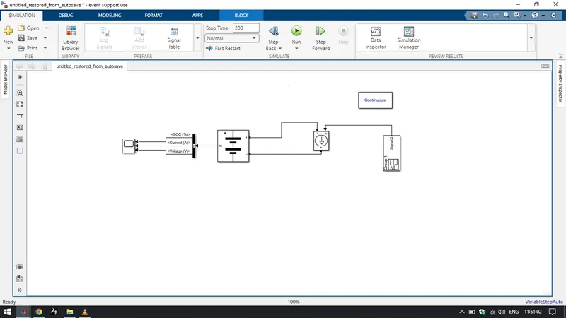
For Siumulink Block are used
Battery- Implement a battery model for most popular battery types. Temperature and aging (due to cyccling ) effect csn be specified for lithium -ion battery type.
Controlled Current Source - Convert the simulink input signal into an equivalent current sorces. The gemrated current is driven by rhe input signa; of the block.
Bus Selctor - This block accepts a bus as a input which can be created from a Bus
creator ,Bus Selctor or a block that defines its output usign a bus object. The left listbox show the element in input bus.
SIgnal Builder block - To use any type of signal till 208 stop time.
Scope - To dispay o/p graph
Powergui - St simulation type smulation aparamaters and preferences.
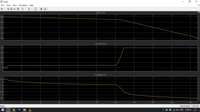
O/P Graph