Project 2
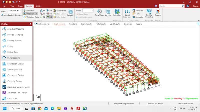
Model & Design a Proposed PEB Warehouse using STAAD. Pro with following Technical specification.
Aim:-
To Model and Design a Proposed PEB Warehouse using STAAD Pro.
Procedure:-
Step 1:-
- Open a STAAD Pro software and Create a File.
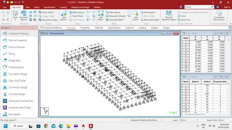
- In Geometry Tab, Create Model using Nodes and Beam commands.
Step 2:-
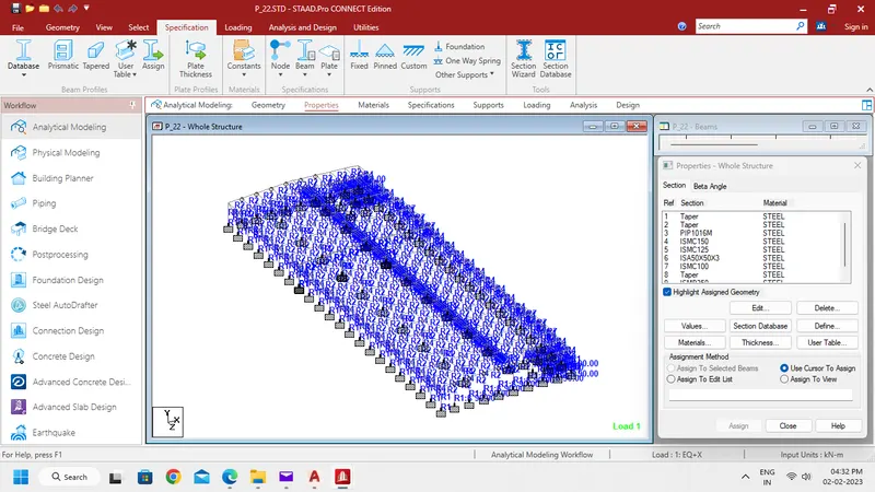
- In Specification Tab, Create and Assign a Sections for the Model.
Step 3:-
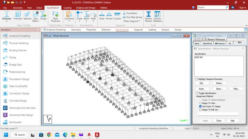
- In Specification Tab, Create a Moment Release and Assign to the Gable End Columns.
Step 4:-
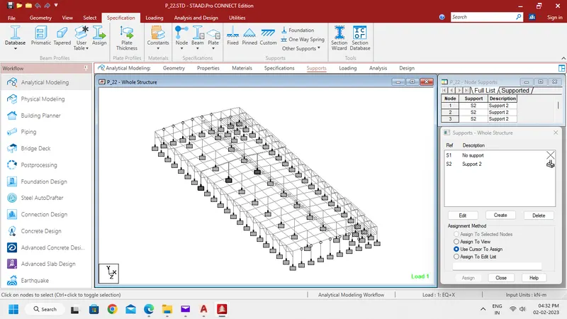
- In Support Tab, Create a Fixed Support and Assign the supports to the all Columns.
Step 5:-
Load Calculation:
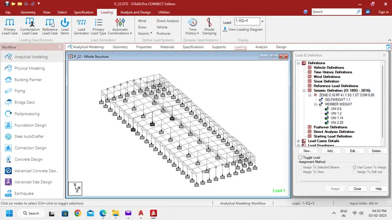
Seismic Load:
Zone Factor = 0.16 (Zone III)
Response Reduction = 4 (Ordinary Moment Resisting Frames)
Importance Factor = 1.0 (Category 4)
Soil Type = 1.0 (Hard Soil – As per Staad)
Type of Structure = 3.0 (Steel Moment Resisting Frames = As per Staad)
25% of Live Load on roof shall be considered for calculation of seismic forces.
100% of collateral load on roof shall be considered for calculation of seismic forces.
50% of (Live load + Collateral load) on mezzanine floor shall be considered for calculation of seismic forces.
100% of Dead load shall be considered for calculation of seismic forces.
Dead Load:
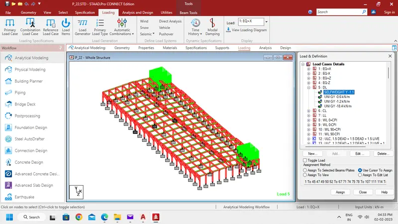
1) Self weight - Assigned to the entire structure as shown in the print screen given below-
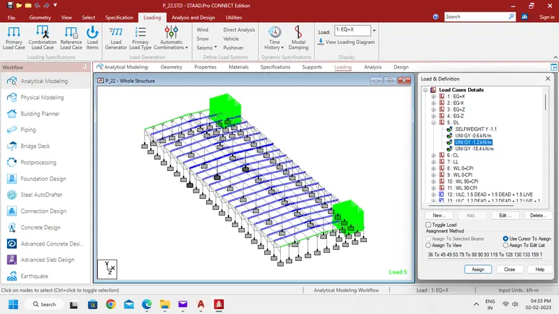
2) Purlin - 10 Kg/m2 and 10 kg/m2 for roof sheeting are as per calculation and print screen given below-
= 20 x 6 (Bay width along span of truss) = 120 Kg/m2
= 1.2 kN/m2 on main rafter
&
0.6 kN/m2 on Gable frame
3) Mezzanine Floor – Load due to 230 mm thick and 4 m height wall around the periphery of Mezzanine Floor.
= 20 X 0.23 X 4 = 18.4 kN/m (on Both Mezzanine Floor)
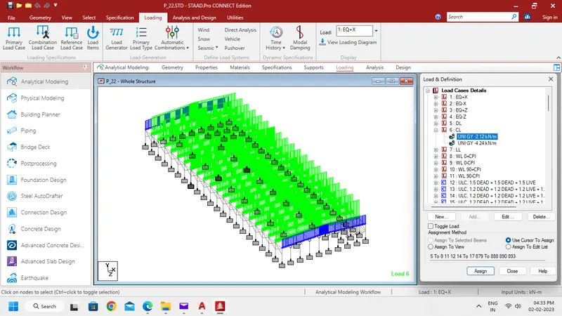
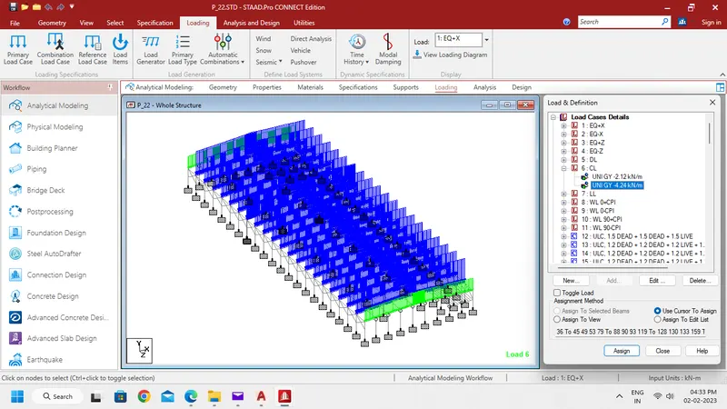
Collateral Load:
On Gable frame - 2.12 kN/m
On Main frame - 4.24 kN/m
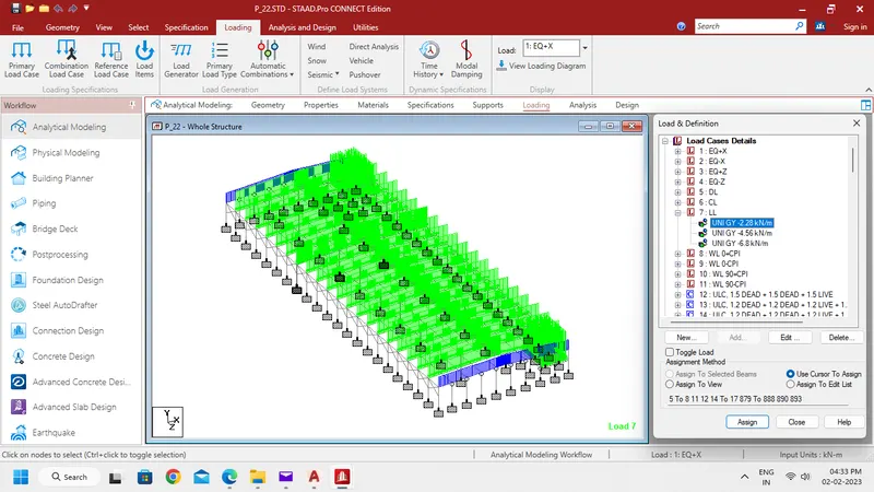
Live Load:
On Gable frame - 2.28 kN/m
On Main frame - 4.56 kN/m
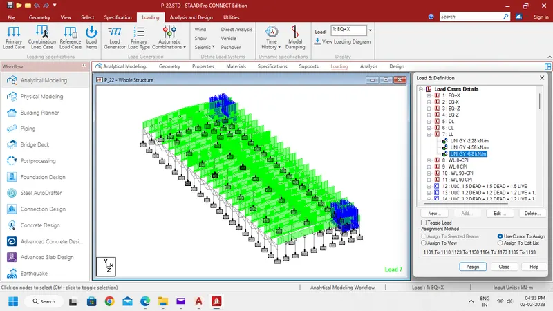
On Mezzanine Floor - 4 kN/m2 or MEMBER LOAD = 6.8 kN/m on all secondary beams except end beams where load will be 3.4 kN/n (4 kN/m2 x 1.78 m (spacing of secondary beams)
- MEMBER LOAD = 6.8 KN/m on all secondary beams except end beams
- MEMBER LOAD = 3.4 KN/m on secondary beams at ends
Wind load:
Basic wind speed = 39 m/s
K1 = 1, K2 = 1.05 (Terrain category), K3 = 1, K4 = 1 (Cyclonic zone)
Design wind speed Vz = Vb x K1 x K2 x K3 x K4
= 39 x 1 x 1.05 x 1 x 1 = 40.95 m/s
Wind Pressure Pz = 0.6 xVz2 = 0.6 x (40.95)2
= 1006.142 N/m2
Ka = 0.8245 (for column)
Ka = 0.8 (for rafter)
Kd = 0.9
Kc = 0.9
Ka x Kd x Kc = 0.8245 x 0.9 x 0.9 = 0.68 < 0.7 so taking least value as 0.72
Design Pressure Pd = Pz x Ka x Kd x Kc = 1006.142 x 0.7 = 704.3 N/m2
= 0.704 KN/m2
Cpi = ±0.2
h/w = 10.05 / 60 = 0.1675
l/w = 170 / 60 = 2.833
External pressure coefficient for walls for rectangular clad building From Table 5 of IS 875 ( part 3) for h/w < 1/2 and 3/2 < l/w <4
|
Wind Angle |
Cpe |
Cpe |
Cpe |
Cpe |
|
Wall |
A |
B |
C |
D |
|
0° |
+0.7 |
-0.25 |
-0.6 |
-0.6 |
|
90° |
-0.5 |
-0.5 |
+0.7 |
-0.1 |
External pressure coefficient for PITCHED ROOF of rectangular clad building From Table of IS 875 ( part 3) for h/w < 1/2
|
Roof Angle |
Wind Angle 0° |
Wind Angle 0° |
Wind Angle 90° |
Wind Angle 90° |
|
EF |
GH |
EG |
FH |
|
|
-0.86 |
-0.4 |
-0.8 |
-0.4 |
On Canopy:
Roof angle = 2.86 degree
Cp( -ve) = -1.08 (Uplift)
Cp (+ve) = + 0.35
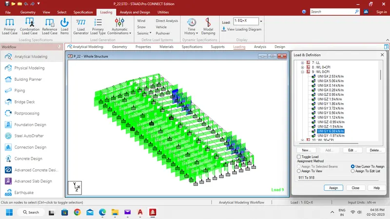
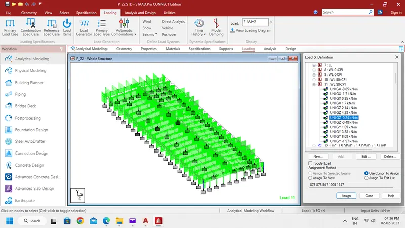
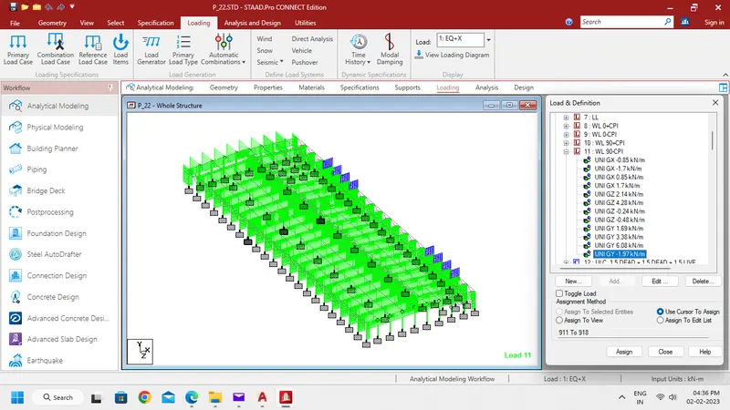
Force on Canopy = -1.08x0.704x8 = 6.08 kN/m (upward)
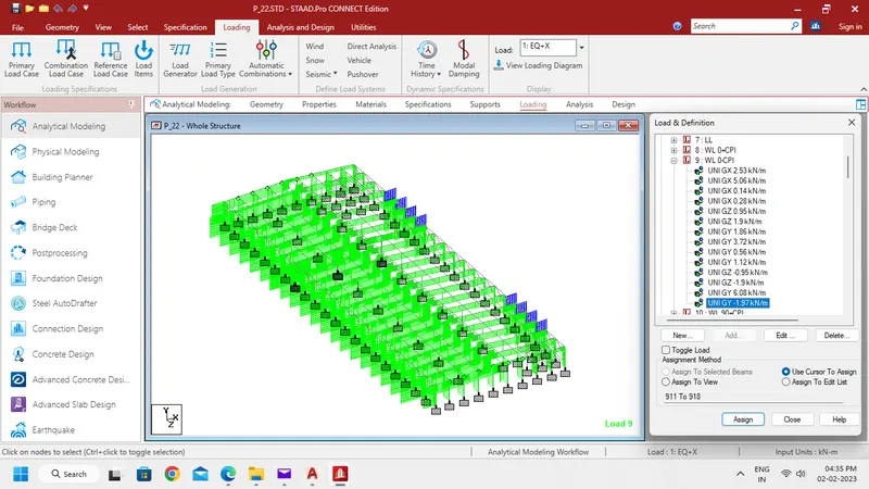
Force on Canopy = +0.35 x 0.704 x 8 = 1.97 kN/m (downward)
For θ = 0° and Cpi = +0.2, Pd = 0.704 kN/m2, MF Spacing = 8m, EF Spacing = 6.75m.
Half of load acting in the Gable Frame
|
Surface |
Cpe |
Cpi |
Cp = Cpe – Cpi |
Wind force on frame |
|
A |
+0.7 |
+0.2 |
+0.5 |
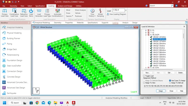
+1.41 / +2.82 |
|
B |
-0.25 |
+0.2 |
-0.45 |
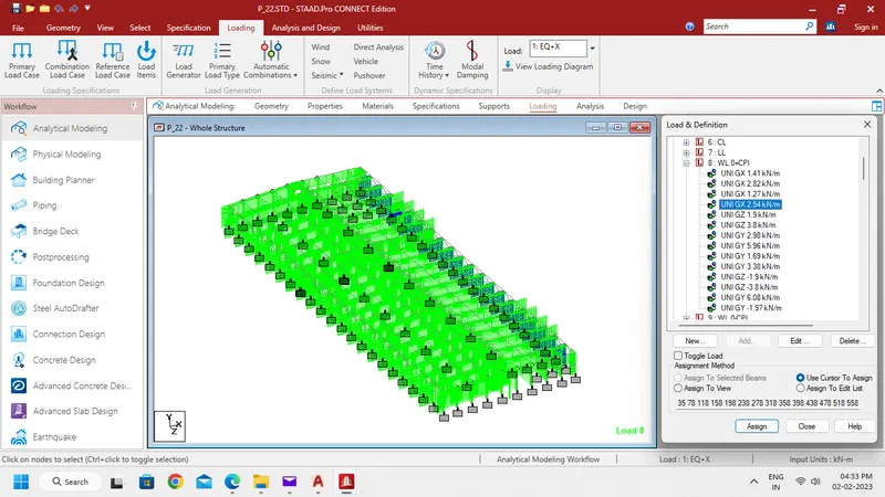
-1.27 / -2.54 |
|
C |
-0.6 |
+0.2 |
-0.8 |
-1.90 / -3.80 |
|
D |
-0.6 |
+0.2 |
-0.8 |
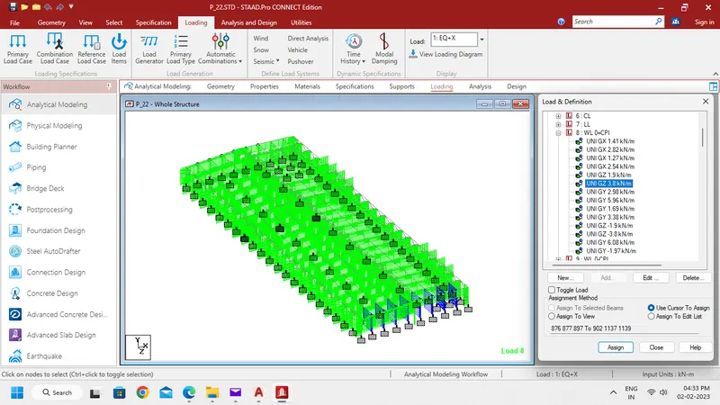
-1.90 / -3.80 |
|
EF |
-0.87 |
+0.2 |
-1.07 |
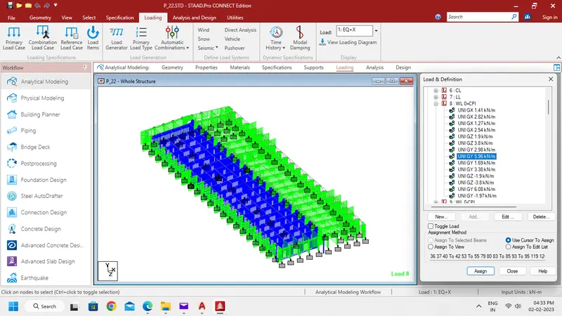
-2.99 / -5.97 |
|
GH |
-0.4 |
+0.2 |
-0.6 |
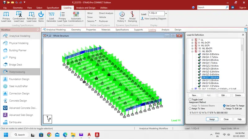
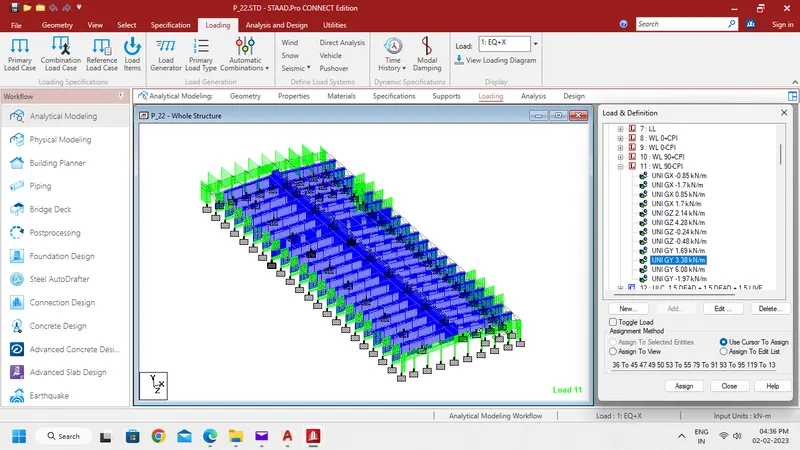
-1.69 / -3.38 |
For θ = 0° and Cpi = -0.2, Pd = 0.704 kN/m2, MF Spacing = 8m, EF Spacing = 6.75m.Half of load acting in the Gable Frame
|
Surface |
Cpe |
Cpi |
Cp = Cpe – Cpi |
Wind force on frame |
|
A |
+0.7 |
-0.2 |
+0.9 |
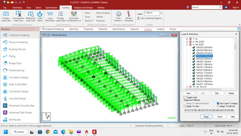
+2.53 / +5.06 |
|
B |
-0.25 |
-0.2 |
-0.05 |
-0.14 / -0.28 |
|
C |
-0.6 |
-0.2 |
-0.4 |
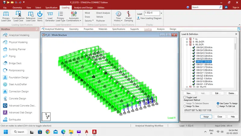
-0.95 / -1.90 |
|
D |
-0.6 |
-0.2 |
-0.4 |
-0.95 / -1.90 |
|
EF |
-0.87 |
-0.2 |
-0.66 |
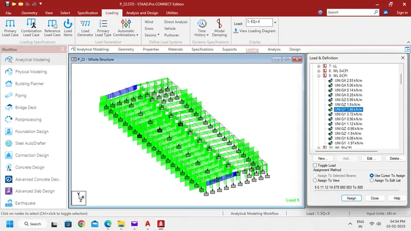
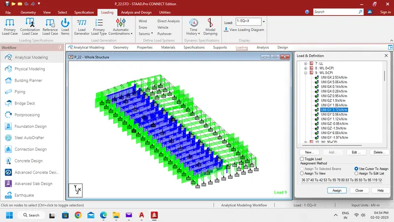
-1.87 / -3.73 |
|
GH |
-0.4 |
-0.2 |
-0.2 |
-0.56 / -1.12 |
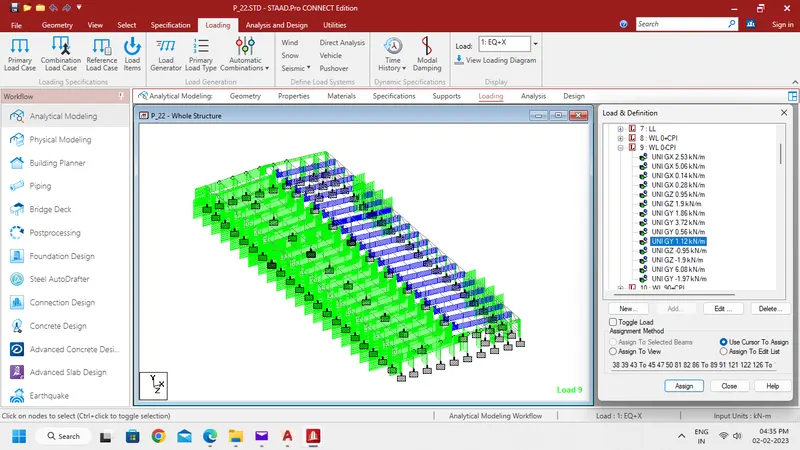
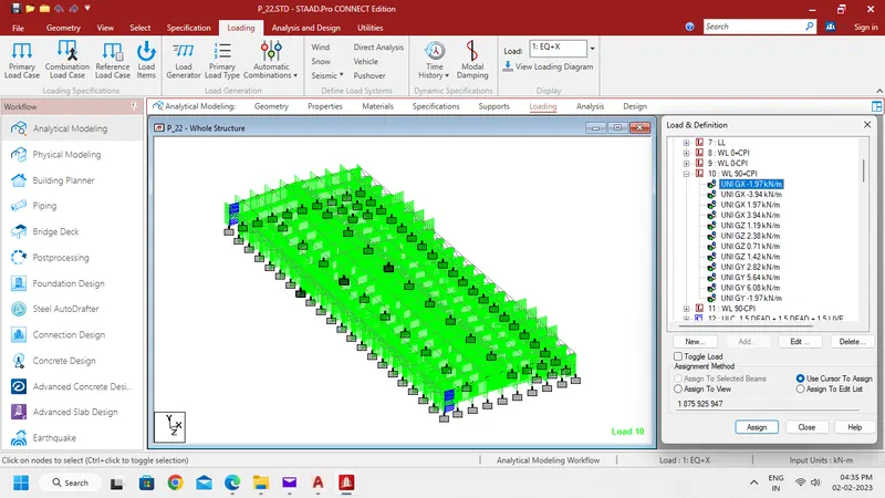
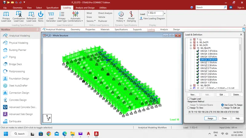
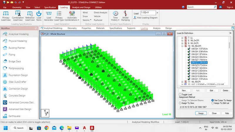
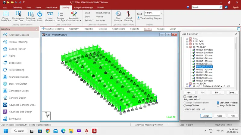
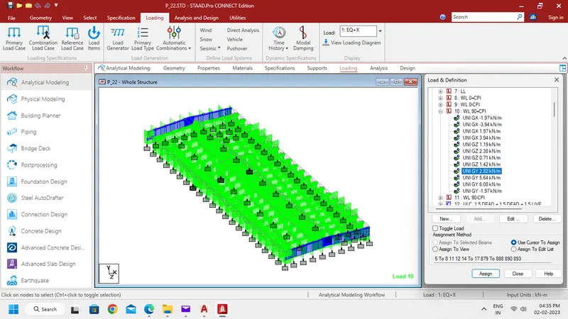
For θ = 90° and Cpi = +0.2, Pd = 0.704 kN/m2, MF Spacing = 8m, EF Spacing = 6.75m.Half of load acting in the Gable Frame
|
Surface |
Cpe |
Cpi |
Cp = Cpe – Cpi |
Wind force on frame |
|
A |
-0.5 |
+0.2 |
-0.7 |
-1.97 / -3.94 |
|
B |
-0.5 |
+0.2 |
-0.7 |
-1.97 / -3.94 |
|
C |
+0.7 |
+0.2 |
+0.5 |
+1.19 / +2.38 |
|
D |
-0.1 |
+0.2 |
-0.3 |
-0.71 / -1.42 |
|
EG |
-0.8 |
+0.2 |
-1.0 |
-2.82 / -5.64 |
|
FH |
-0.4 |
+0.2 |
-0.6 |
-1.69 / -3.38 |
For θ = 90° and Cpi = -0.2, Pd = 0.704 kN/m2, MF Spacing = 8m, EF Spacing = 6.75m.Half of load acting in the Gable Frame
Step 6:-
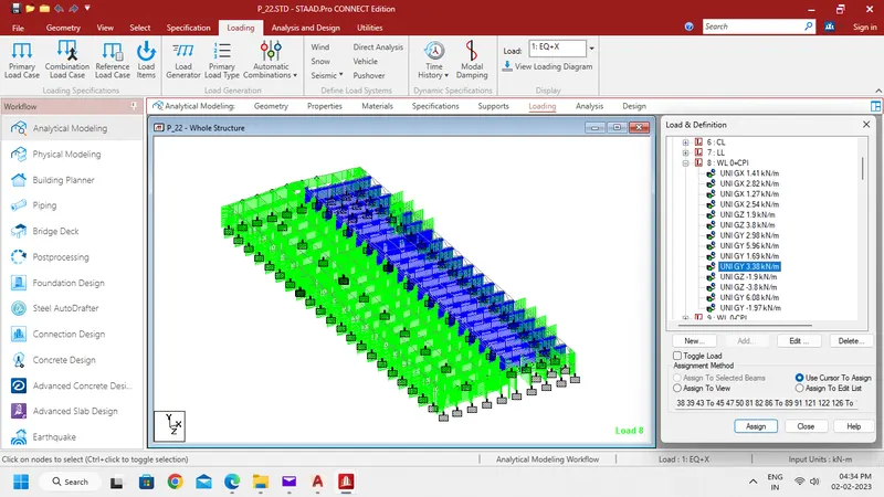
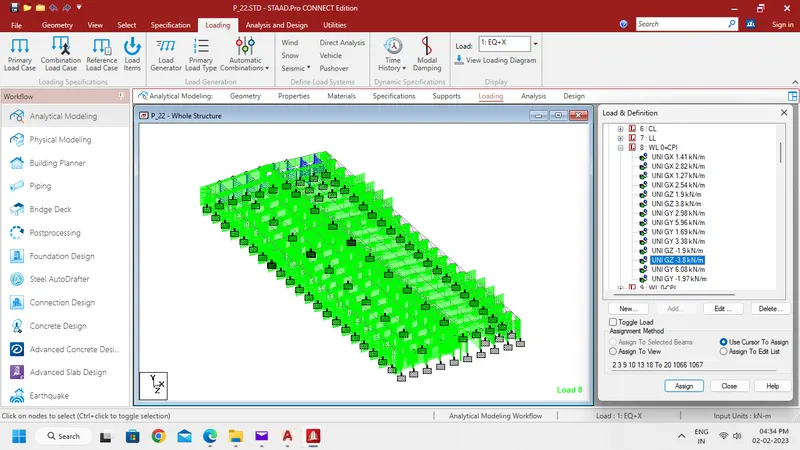
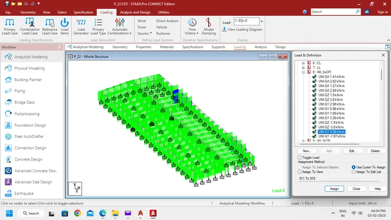
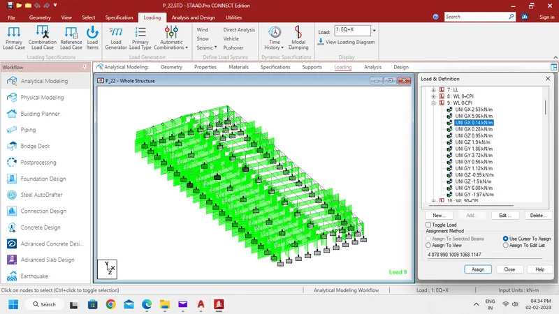
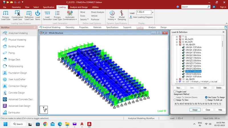
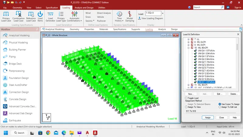
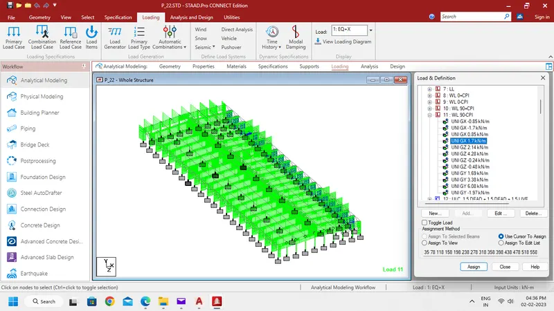
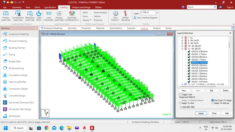
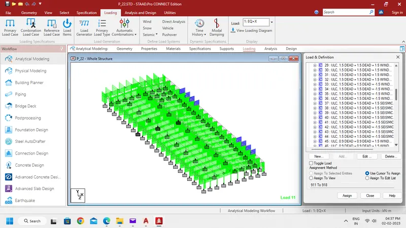
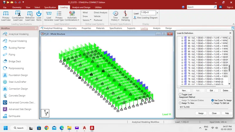
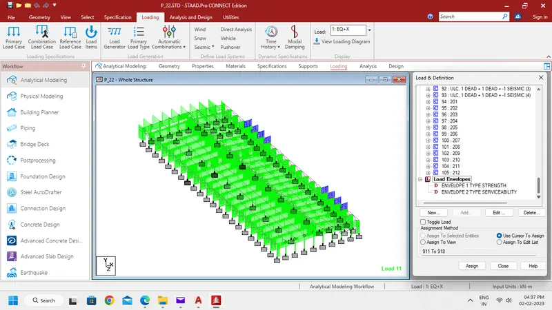
- Load Assignment and Load Combination creation and Assignment.
Step 7:-
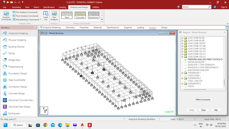
- In Analysis Tab, Create and assign Parameters to the Model.
Step 8:-
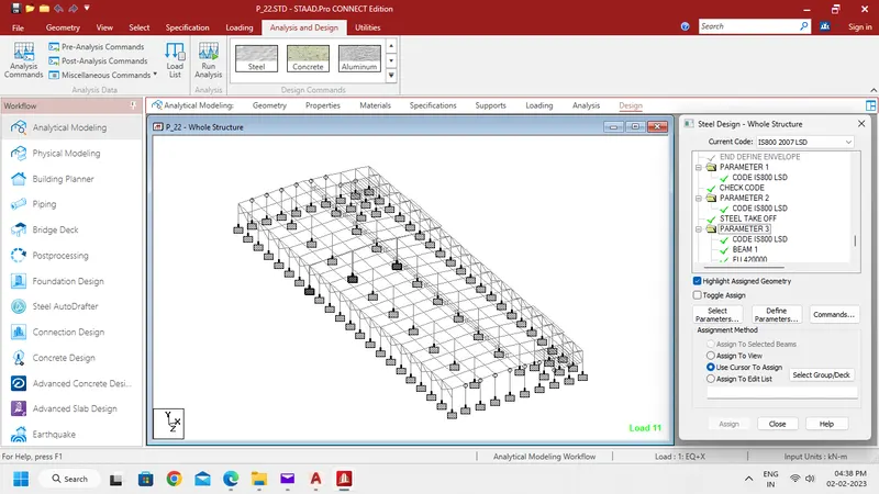
- In Design Tab, Create and assign Design Parameters to the Model.
Step 9:-
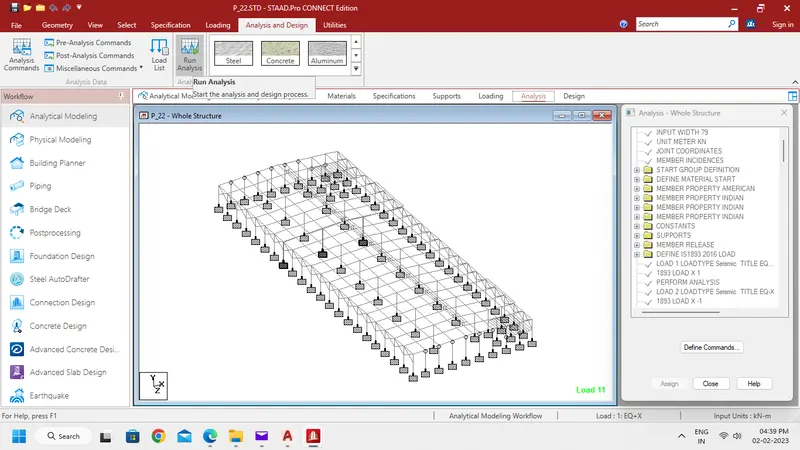
- In Analysis Tab, Click Run Analysis.
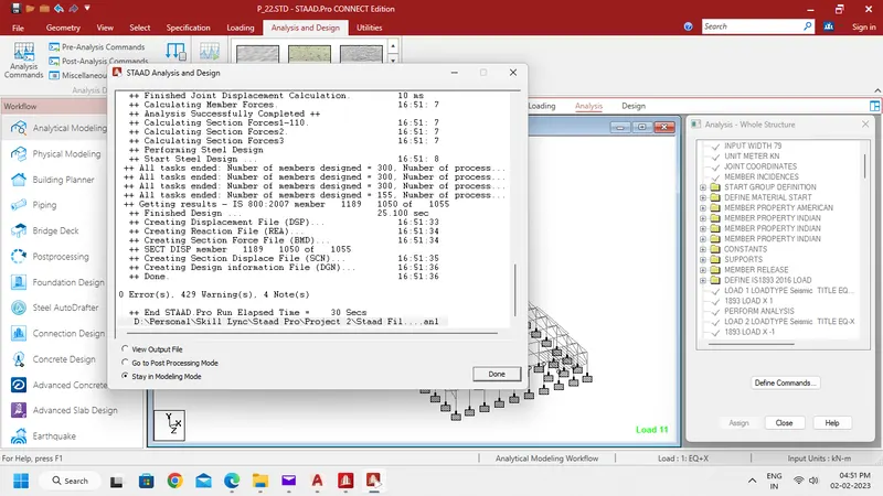
- Output shows 0 Errors.
Result:-
- The Proposed PEB Building was Modelled and Designed using STAAD Pro successfully.