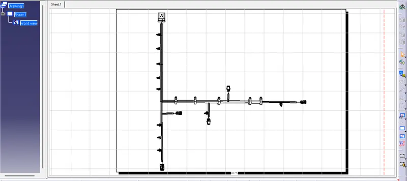
Project 2
STEPS INVOLVED IN WIRING HARNESS ROUTING OF THE BACKDOOR
- Here we are using 6 connectors constitute of one inline connector, 2 connectors for tail lamp, one for camera sensor, one for wiper motor, one for number plate light and for support we will use Fir tree clip & p clamp
- Lets download all the required components
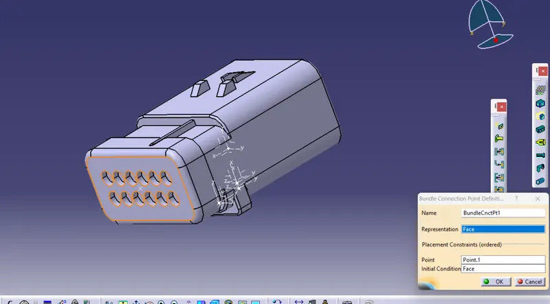
- Define the connector as an electrical part and define the bundle point, and connector connection point of all the connector
- Add the connectors in to the connector catalogue
Inline connector
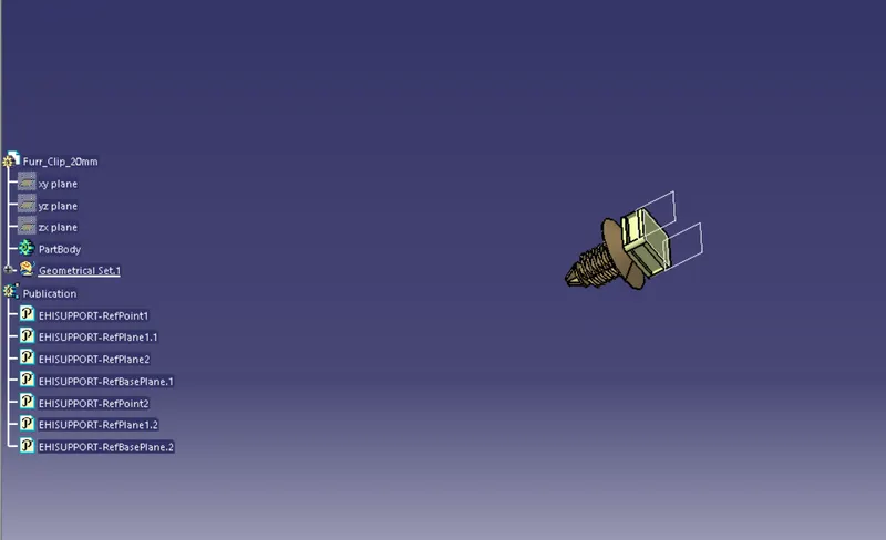
Fir tree clip
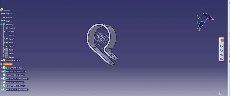
P clamp
- Create a product file and name it as context Wiring harness context file
- Create a product file for geometric bundle assembly and insert all the electrical parts in to this product file
- Copy the geometric bundle assembly in to main context file
- Import the 'Backdoor ' CAD date in to the context file
- Arrange the components like inline connector, Fir tree, P clamps & the other connectors according to the layout
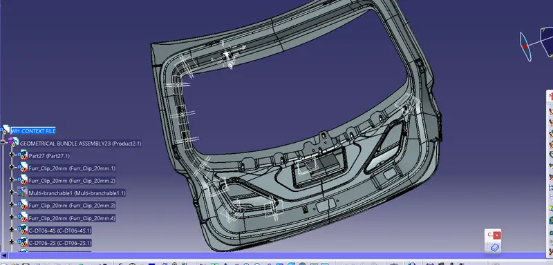
- Now let's start the routing
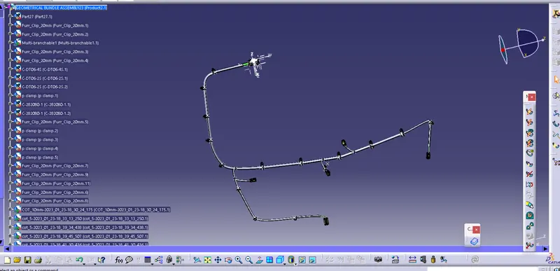
- Lets activate geometrical bundle and click on geomtrical bundle assembly product file
- start the routing from inline connector
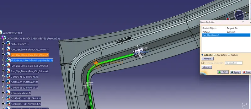
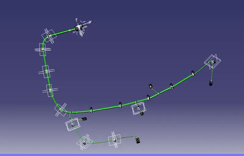
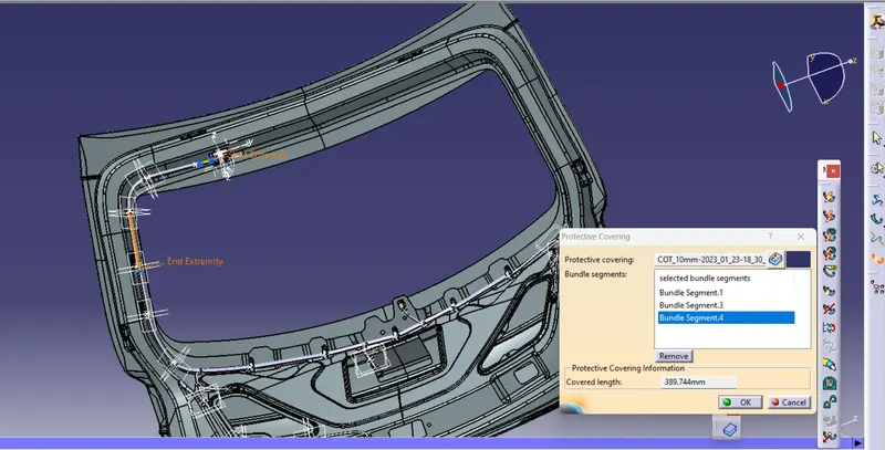
- After completing routing ,let's cover the bundles by COT tubes to protect it from surroundings
FLATTENING
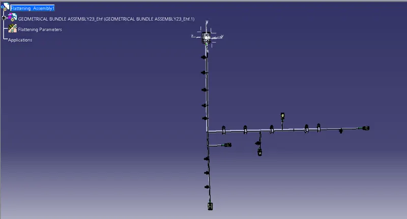
- Create a product file and name it as flattening assembly
- switch to flattening workbench
- Initialize the flattening parameters
- Extract the geometrical bundle assemblyfile
- Click on flatten and select the face and select all bundles
- Use the appropriate command to modify the flattened assmbly according to your perspective
- After flattening manipulate the clips or connectors to the front view inorder to view properly
DRAWING FILE
- Create a new drawing file and save it
- Click on front view and select the face from the flattening assembly file
- After importing 2D file in to drawing change the view properties