Project 2
Step 1: Creating Assembly
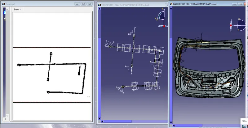
- A Context Assembly for Backdoor Wire Harness has been created, which will work as the main assembly as shown in the figure above.
- A Context Assembly will contain Backdoor Assembly data and Backdoor Wire Harness Geometrical Bundle Assembly.
Step 2: To Define the Connectors and clips.
- Once the File is Downloaded, Open the File Using CATIA V5
- Using the Part design model, we define entry, Exit, Base points, and Planes
- After determining the points and planes open the file in Electrical Part design
- Now we need to define the part as a Support using the Define support Part
Step 3:-
These are the steps required to do this project-
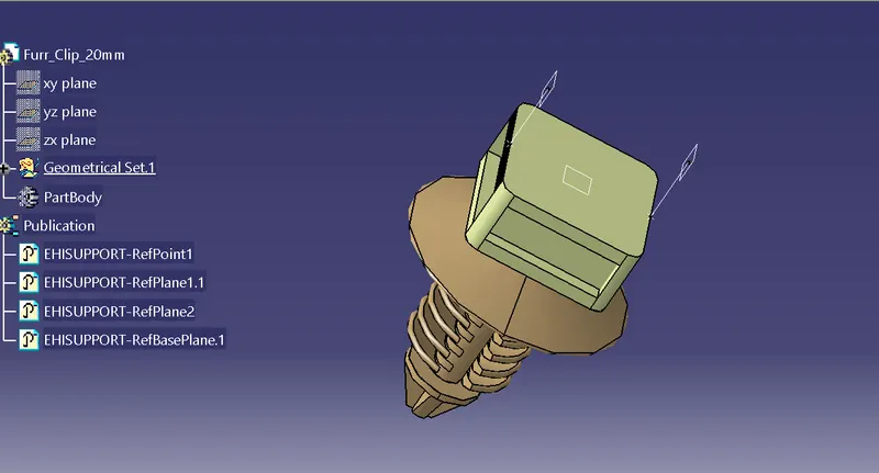
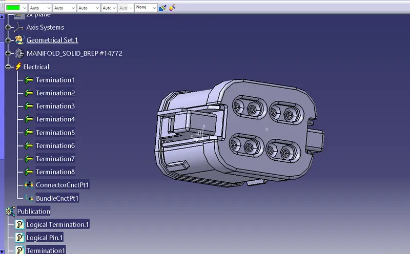
- Create the required geometrical parameters for connector
- Create a bundle entry point
- If connector accommodates clip then define a geometrical parameter for the clip
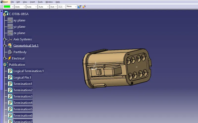
- Define part as a connector or mounting equipment
- Create bundle connection point
- Create a connector connection point
- Create a cavity connection point if there is a clip
- Switch to Electric part design and define part as connector
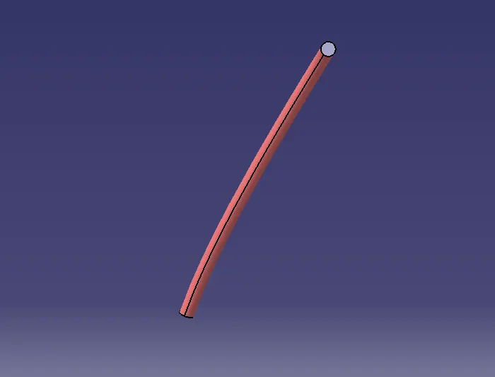
- As there is no file to download for corrugated tubes we have to make each type of corrugated tubes and them into a catalog so they can be used at a later stage.
- In the electric part design workbench, define the protection part, and give the necessary dimensions for the COT tube. Give values for inner diameter and thickness.
- Create a COT tube catalog.
- Give a name to the catalog and define its type as “conduit”. For insulation tape type is “electrical”.
- Define part family name.
- Save the “Slit COT” catalog.
- Add all the created Corrugated tubes to the catalog individually.
Step 4 :-mountinig clips to required position.
- For the placement of the clips and the Connectors we used various commands such as manipulation, snap, smart move, compass, and so on.
- The entire assembly is ready for routing
Step 5: Adding protective coverings and guiding channels top shell to harness bundle
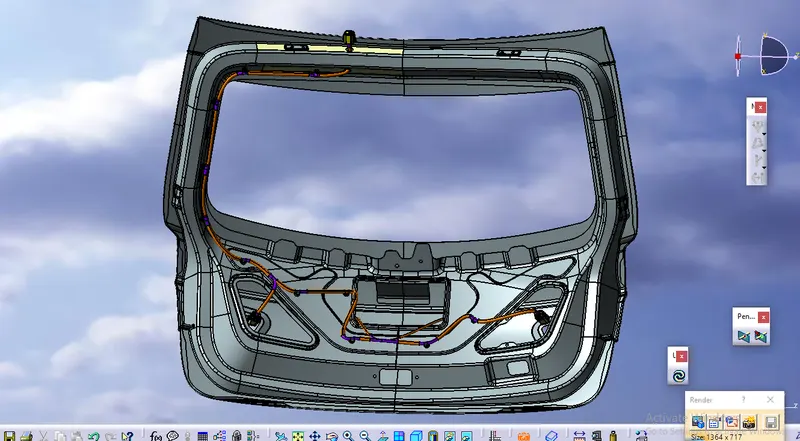
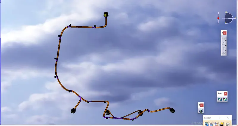
Here is the below figure, we have done with the whole wiring harness routing for the Backdoor. Now, we have to add protective coverings to all bundle segments
Step 6: Checking bundle continuity
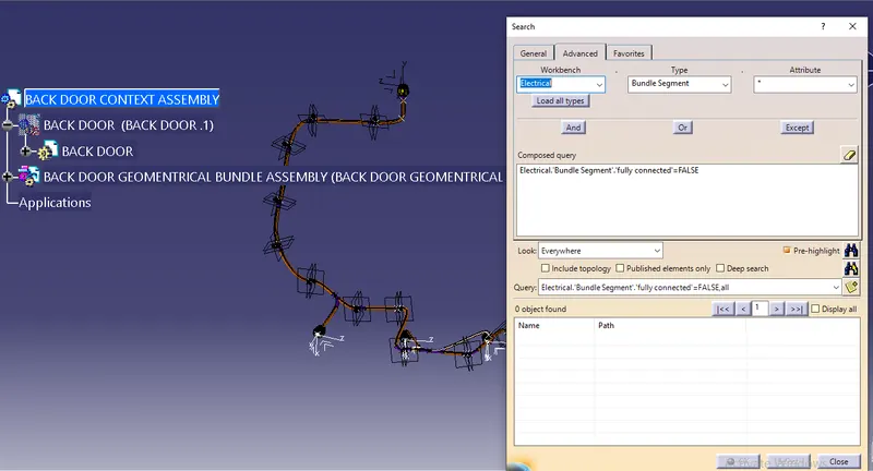
In this step, we must first ensure that multi-branch capability is selected before proceeding to Edit>Search>Advanced>Workbench-Electrical>Type-Bundle Segment>Attribute-Fully Connected.
Selecting 'True' displays all connected bundle segments while selecting 'False' displays all non-connected bundle segments.
In this case, we chose the 'True' option and searched for results. As shown in the figure below, all of the bundle segments are highlighted, indicating that they are all electrically connected.
Step 7: Creating flatten view of the Backdoor Wire harness geometrical bundle assembly
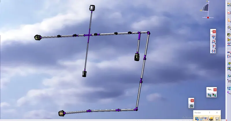
In this step, we will use Catia V5's Electrical Harness Flattening workbench to create a flattened view. We should also ensure that the flattening file is saved in the same folder as the other harness assembly files.
- The bundle assembly was extracted into a Back door wire Harness Flattening Product file, which was then flattened along the face of the interconnection connector.
- We developed a flattened view.
- we must rotate bundle segments connecting to the four cam-shaft connectors using the 'Rotate' feature of the flattening workbench.
- It should be noted that the 'face' of the interconnection connector serves as the flattening plane, so we must rotate the bundle segments only along that plane.
- We used various features such as bend, rotate, and roll to streamline the harness for better representation.
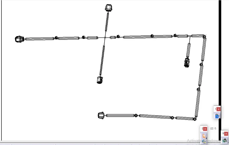
The flattened view's final representation
Step 8: Creating a flattened view drawing for the wiring harness assembly
In the figure above, we're creating a new drawing file and defining all of the required drawing parameters. The front view of the Backdoor wire Harness Flattening Product file must be inserted into the Drawing file. As shown in the preceding figure, we must define drawing properties. It should be noted that the 3D wireframe is always ON in the 'Dress up settings. If this option is not enabled, the bundle segments will not be visible in the drawing view. the Backdoor wire Harness Flattens view's final Drawing view