Project 2
Roadway projects are also sometimes of road widening and just top pavement, where capacity has to be improved and existing pavement has to be strengthened. In this mini project, you will have something similar scope.
Using the same data set, you have to complete this mini project. Below are the details –
- Existing 2 lane undivided rural highway of 11’ travel lanes + 4’ shoulder. Typical cross slope is 2.0%
- Speed of 50 MPH, rolling terrain, major arterial category of the highway remains the same.
- Proposed condition – existing 11’ lanes to be made 12’. Adding 1 center turn lane of 12’ and paved shoulder of 10’.
- End conditions of cut/fill/ditch – 1:6 preferred and 1:4 desirable for front slope and 1:4 preferred and 1:3 desirable for back slope.
- Entire typical cross slope to be maintained at 2.0%
- Use existing alignment & profile as proposed conditions.
- Design Site layout.
- Design template
- Develop a corridor model.
- Submit your DGN files – each dgn is separate
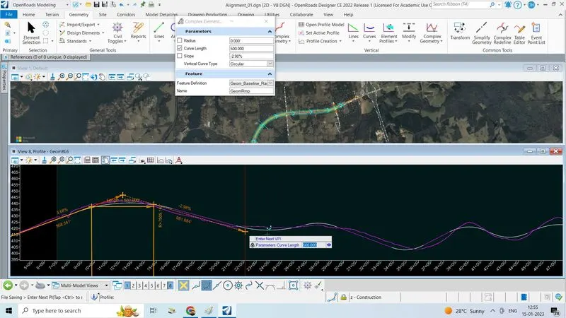
1. Use existing alignment & profile as proposed conditions.
2. Design Site layout.
3.Design template.
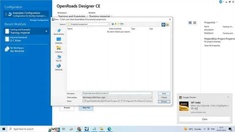
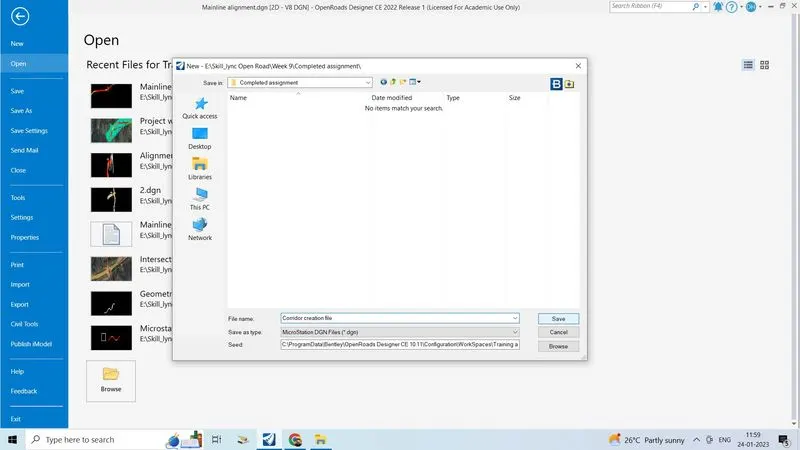
- Creating the new 2dseed file for creating the new templates and designing the corridor
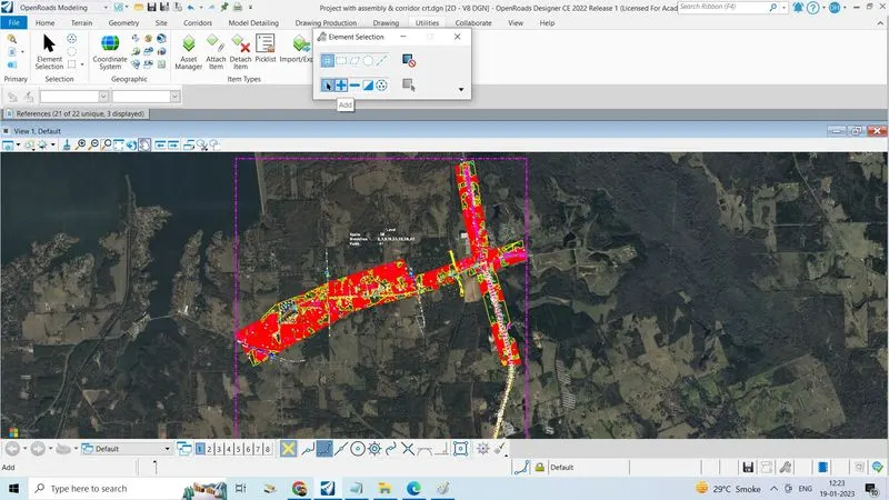
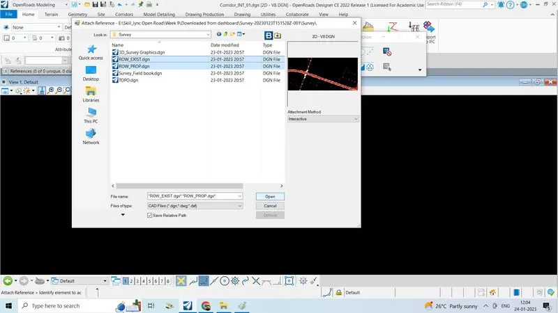
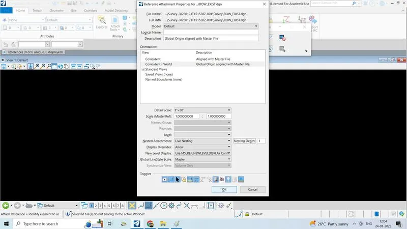
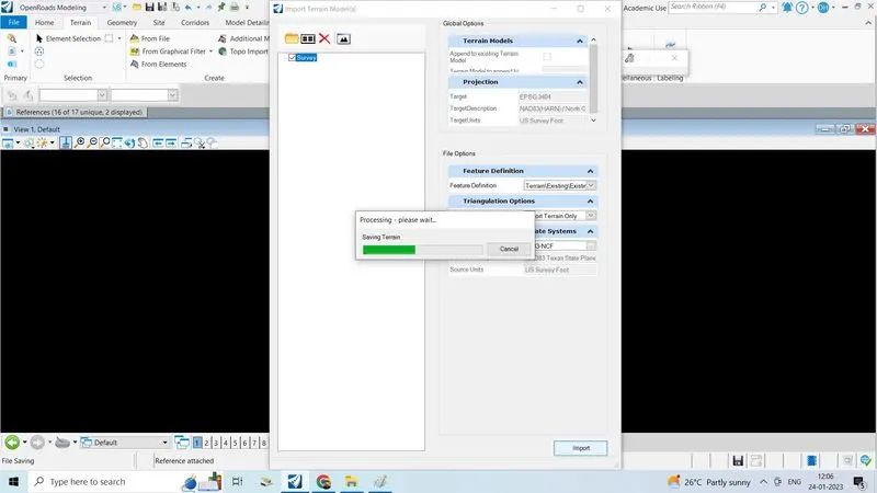
- Take reference created alignment, offset alignment with created profile, terrain model with an interactive method, model as default or 3d default, live nesting, depth 1.
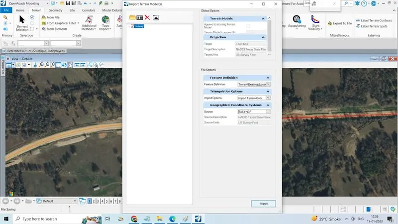
- Set the co-ordinate system as TX83-NCF
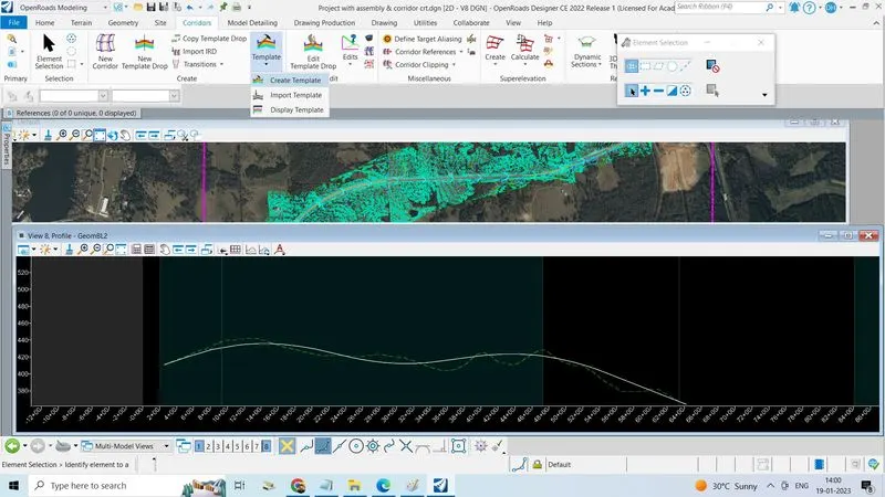
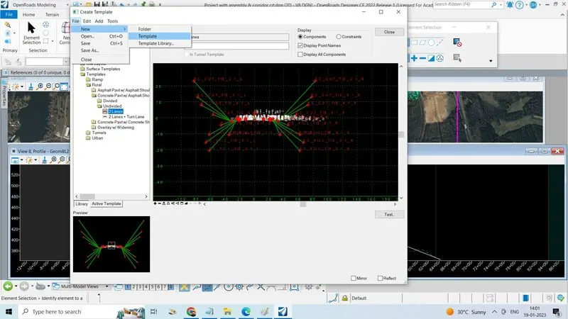
- Now go to corridor tab, click on template
- Click on create template
- Click on file, click on new template give name as created templated
- In template library, double click on payment new, select the two-lane concrete pavement
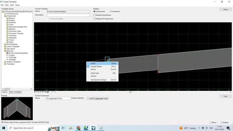
- Double click on 2 lanes or single click and drag in to the layout sheet ‘
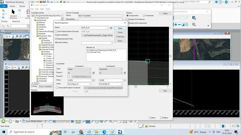
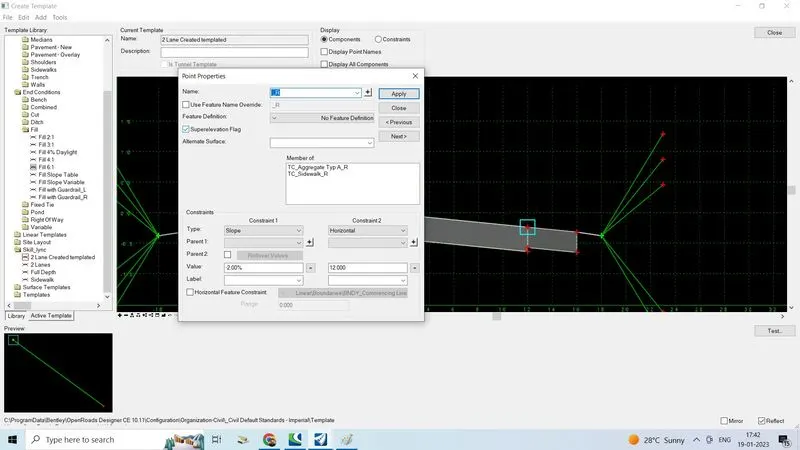
- Double click on the point or select and right click on the point of the pavement
- Click on edit point properties will open give the cross slope and lane width as per IRC
- Set the feature constraint now apply
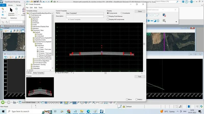
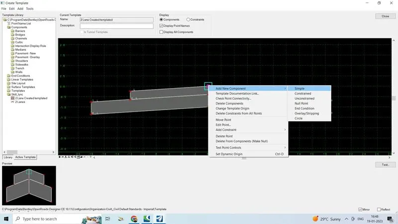
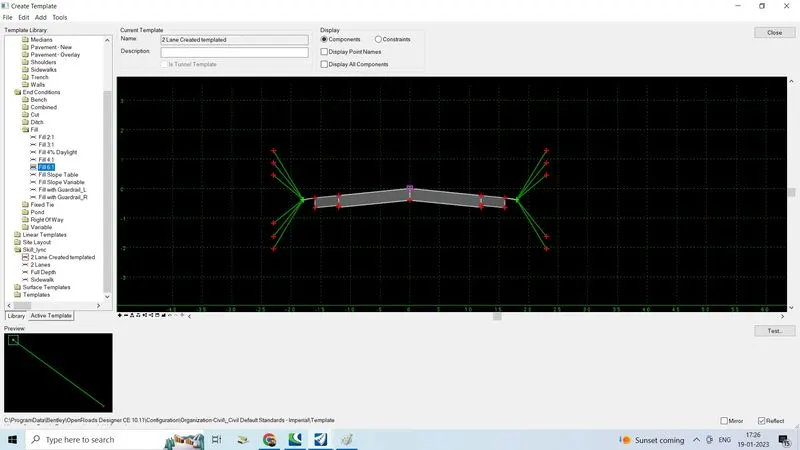
- Now apply the shoulders, sidewalk, curbs, end condition if there is s necessary with a conditions
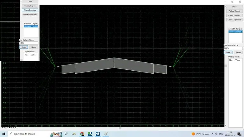
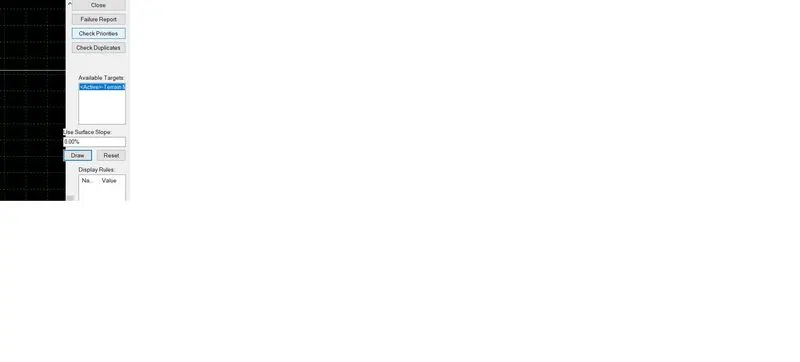
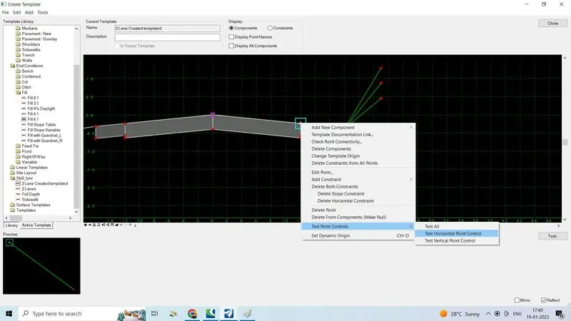
- Click on test, test end condition layout is opened
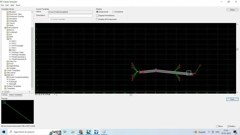
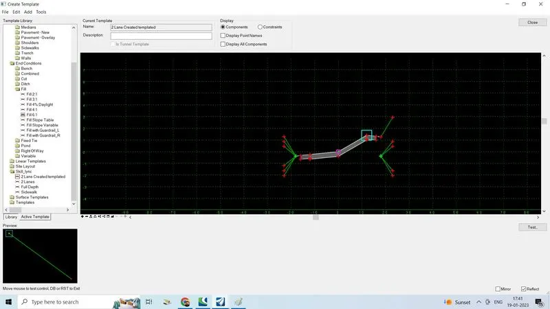
- Now click on draw option then the horizontal will come upon the assembly and it check weather the end condition are reflected or not if it is reflected only one the created template correct
- Click on check priorities and give the serial wise if it not correct
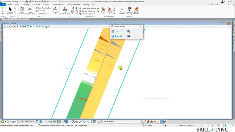
- Set the superelevation points at the top pavement layer so
- Select and right click on each top pavement and click on edit point then
- Check mark on the superelevation flag
- Click apply
4.Develop a corridor model.
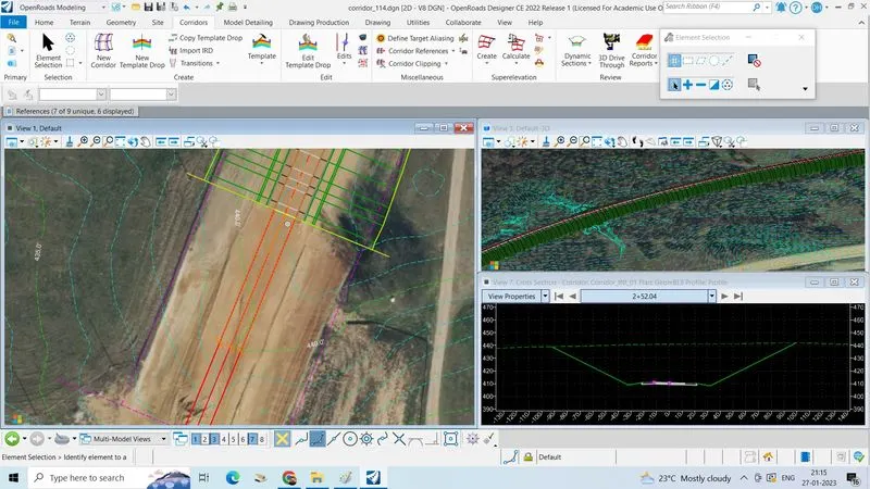
- Go to corridor tab in create section, click on new corridor
- Select the feature definition give the name as “corridor_INT_01”
- Locate corridor baseline right click reset for active profile
- Click on create template that previously created click ok
- Left click on the alignment select point from where to where the template wants
- Select start station and end station give drop interval and then left click
- Corridor is created
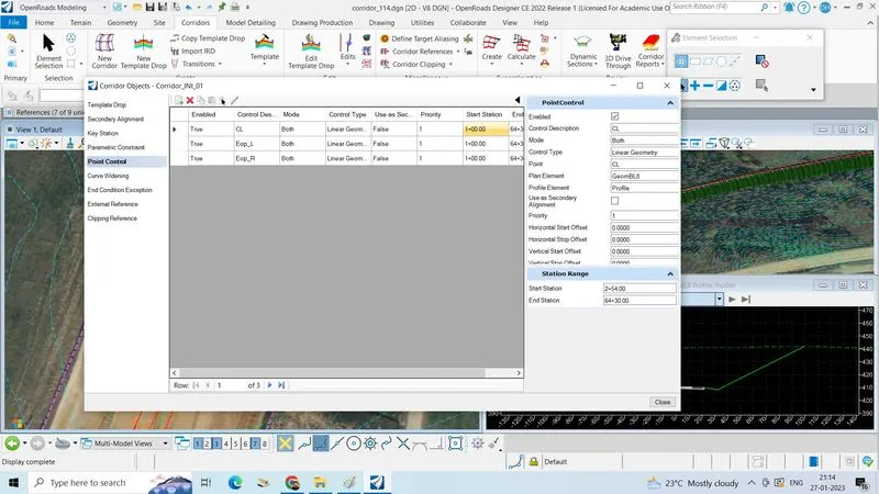
- Now we will add the control points CL, EOP, EOS
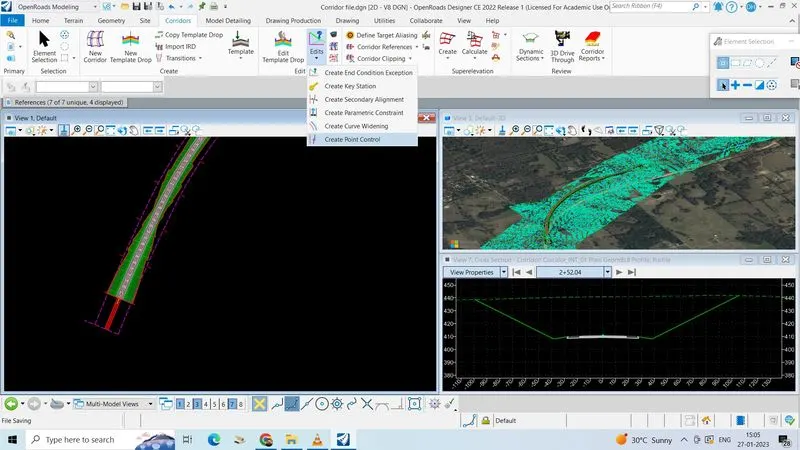
- Now go to corridor tab, click on edit
- Click on create control point, locate the corridor
- Start station, if we want to create CP on CL then select the parameters as CL
- Locate the point that in the CL
- Select parameter control type as linear geometry
- Now locate plan or profile
- Select secondary element NO
- Parameter priority 1 remaining all zeros
- Likewise do the same procedure for EOP, EOS also
- If any edits will arrive click on corridor objects and do it
- If any changes have to make in templates like removing end conditions ..etc then
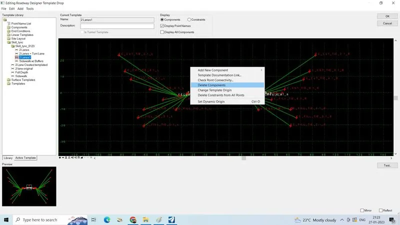
- Click on edit template drop
- Locate the template drop
- In template library right click, click on delete component
- Delete the 3:1cut /fill condition
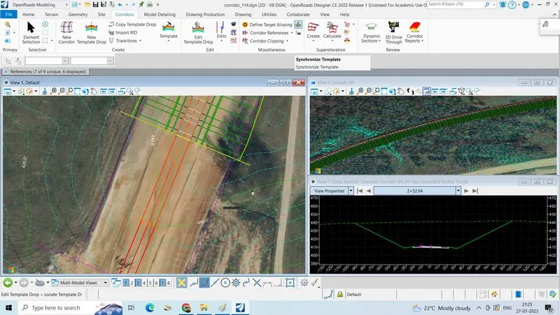
- Go to file click save
- Click on synchronize the corridor will get update and sync with change once
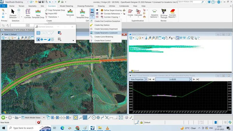
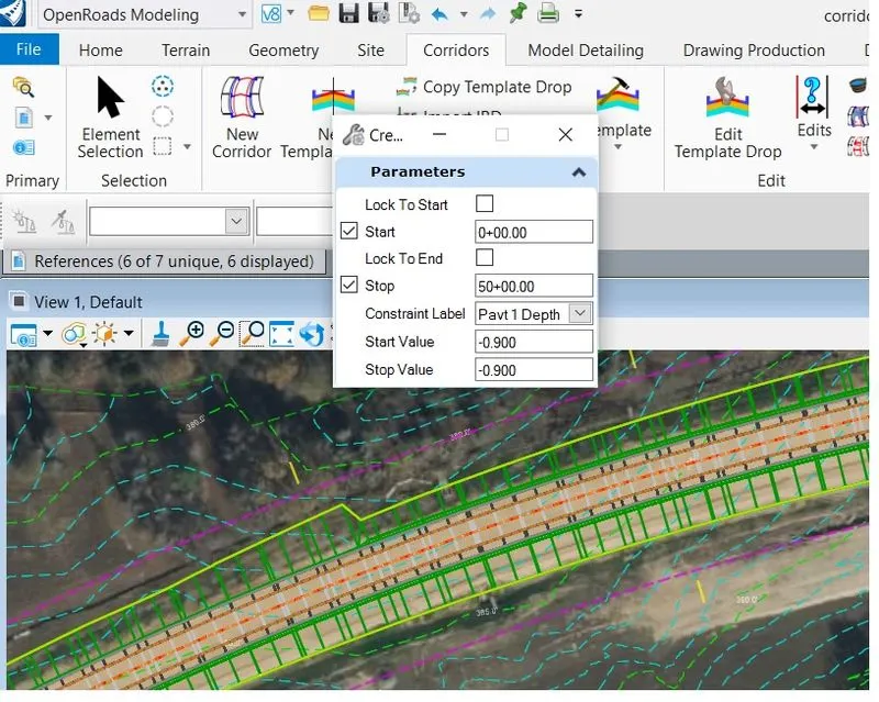
- If we want change depth of pavement, shoulder…. etc. in corridor tab
- Click on edit
- Click on to create parametric constraints
- Locate the corridor
- Select the start station and end station
- Constraints label as pavt depth
- Give the start value and stop value left click
- Pavement thickness is changed
- Do the same procedure for slope also
5.Submit your DGN files – each dgn is separate
- Created terrain model "Terrain model.dgn" file
- Created alignment with an active profile "alignment with profile.dgn" file
- Created offset with an active profile "offset with profile.dgn" file
- Created Template "Template.dgn"
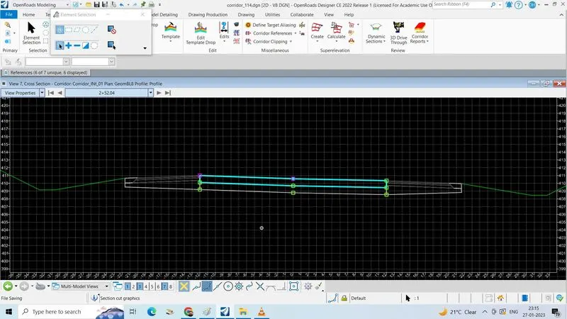
- Created corridor with crossections "corridor.dgn" all the file are seperated