Project 2
Q.1
Aim-
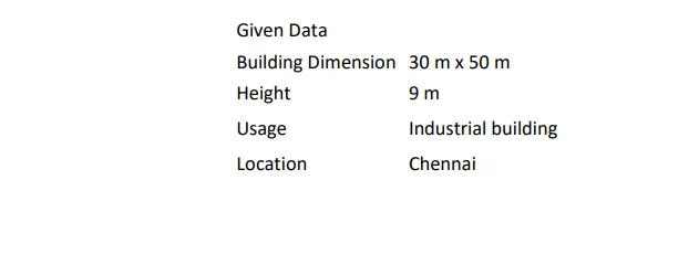
Design a Warehouse Building located in Chennai using STAAD Pro Connect Edition. The specification must be as follows:
|
Width |
30m |
|
Length |
50m |
|
Eave Height |
9m |
|
Bay spacing |
6m |
|
Soil type |
Medium |
|
Safe Bearing Capacity |
200 kN/m2 |
|
Roof slope |
1 in 12 |
Assume suitable sections for structural elements. Follow IS800:2007, IS1893 and IS 875.
INTRODUCTION-
- In Staad pro we are able to design any building like warehouse building and residential building etc.
- Staad pro also give a option of analysis warehouse building like how much deflection generted in building due to load combination, Bending moment diagram etc.
- We can extract the all results from staad software in pdf form or in the form of hardcopy.
PROCEDURE-
- We will create a new project with appropriate name and assign units in model like metric unit.
- Project information also insert in stadd new opening page like project name, Client detail, Revision no. etc.
- Now we can create warehouse modal.
- Nodal method use to create origin of first point.
- second point will set at 30m in x-direction and one another point at mid of these two point will set in same direction.
- Insert node and with copy and paste node paste at 9m.
- add beam and use intersect selected beam and draw beam.
- Mirror command use and mirror these point respect to selected point.
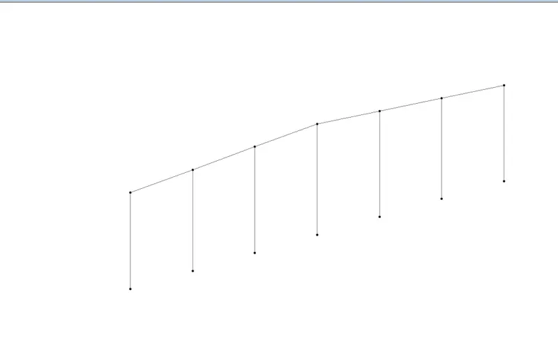
- This gable part create in z direction till 50m with the use of translational repeat option.
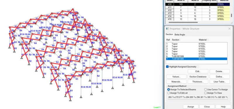
- Now assign the properties to all structure structure like column I-section with appropriate size and tube shape purlin and tube shape braces assign to model.
Specification-
- We have to release Bending moment at the end of wind column and release B.M at start and end of purlin member.
- Braces design as tension member.
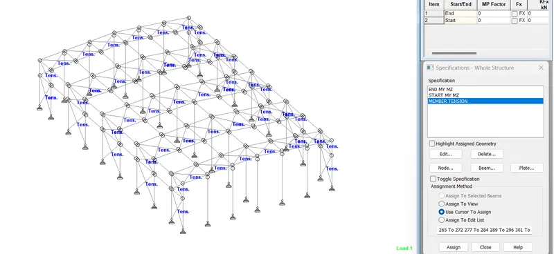
- Add bracing at outer side and on the roof with appropriate spacing and purlin to support the roof cladding and wall cladding.
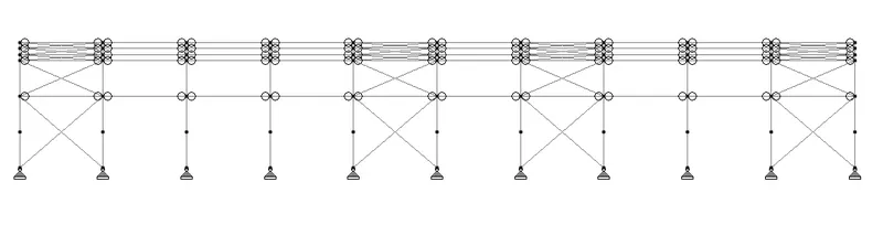
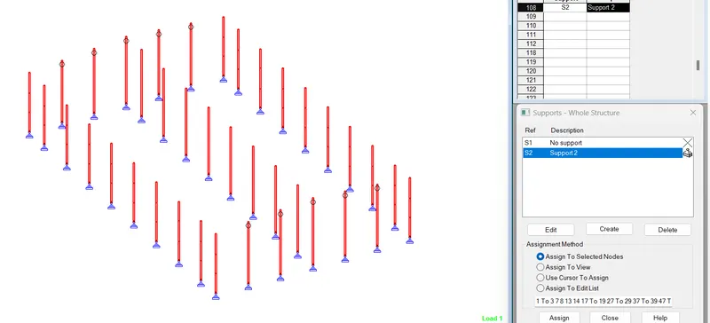
Support- We will assign pin support to the column to minimize the bending moment at the support.
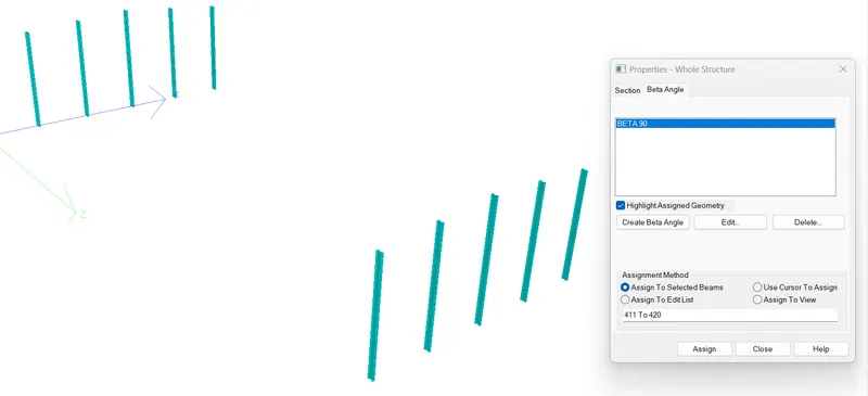
- Change the orientation of gable wind column to avoid buckling due to wind force.
Loading-
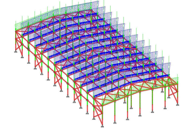
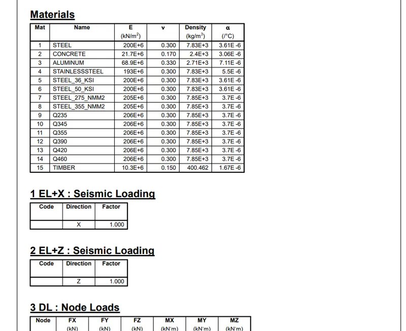
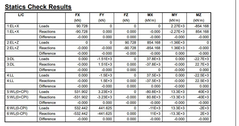
Assign all important load and load cases.
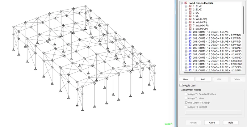
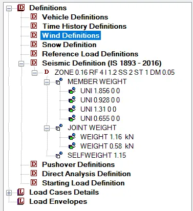
- Define the E.Q load and wind load under the load cases detail and define earthquake and wind load under difinitions.
ANLYSIS RESULT-
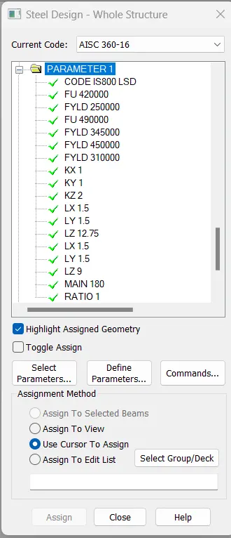
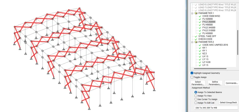
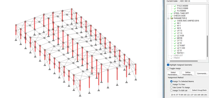
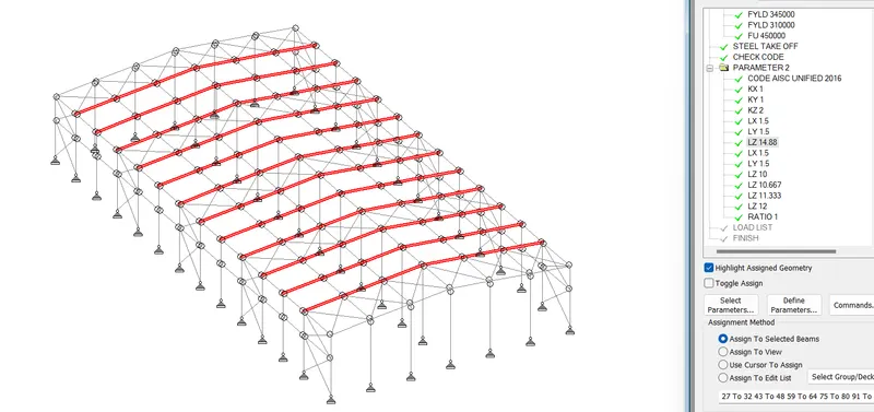
Design parameters in staad pro-
Q.1B
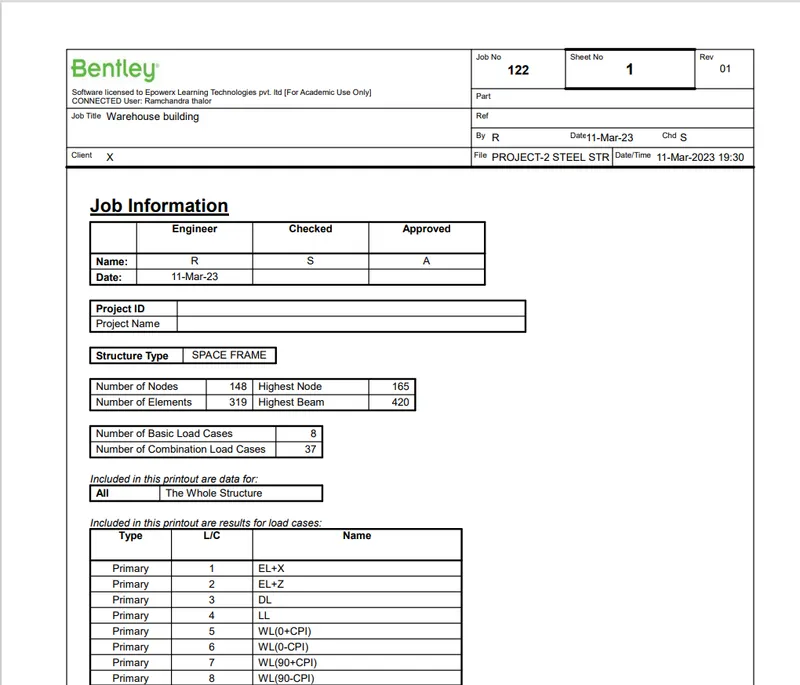
AIM- DESIGN BASIS REPORT FOR THE PROJECT-
- After completed postprocessing in staad we will choose reports tab.
- Under the report tab we will click on report serup option.
- Here we can set input and output data for report.
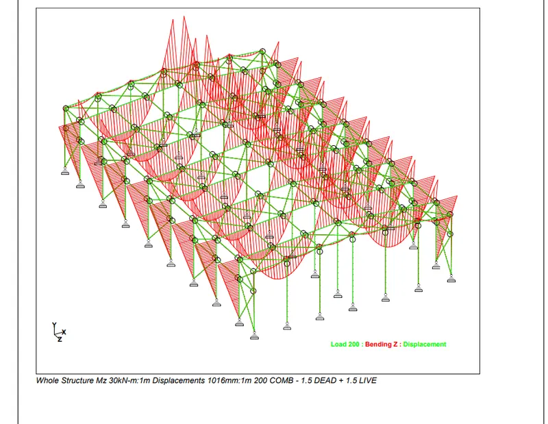
BENDING MOMENT DIAGRAM FOR DEAD LOAD + LIVE LOAD CASE-
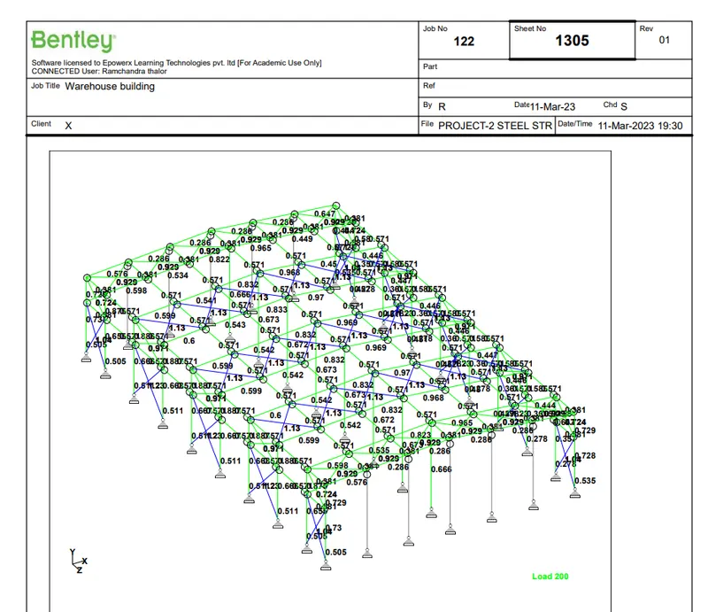
UTILIZATION RATIO-
3D PICTURE-
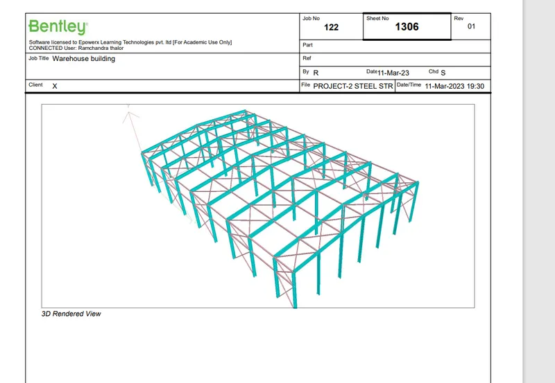
RESULT- Warehouse created include all the design parameter and also assigned these parameter to the steel skelton and on the basis of design result a report also prepared.
Q.1C
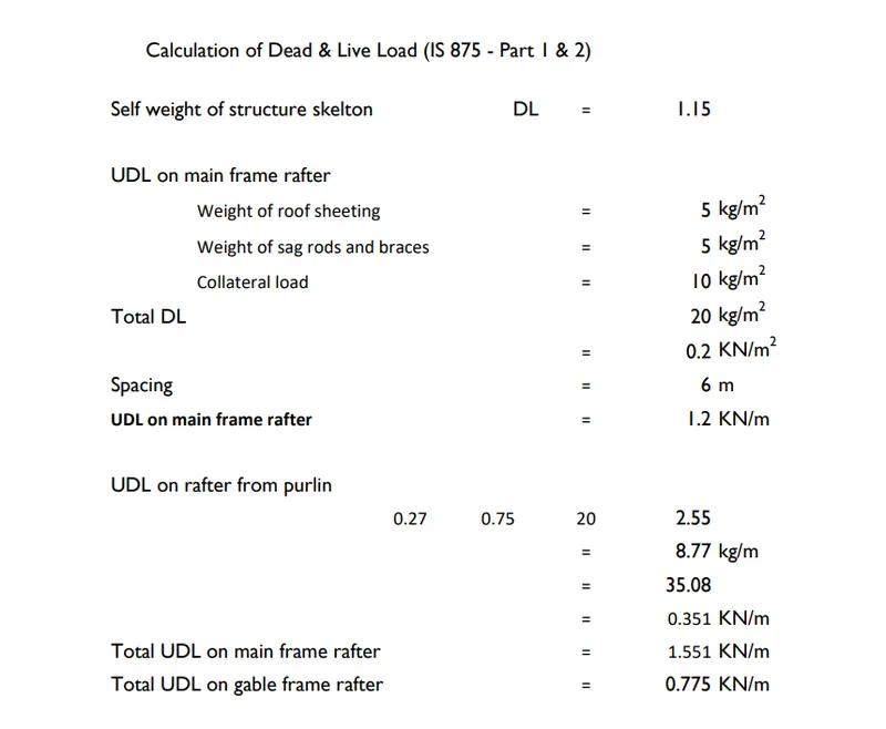
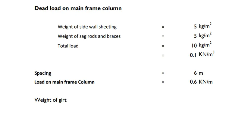
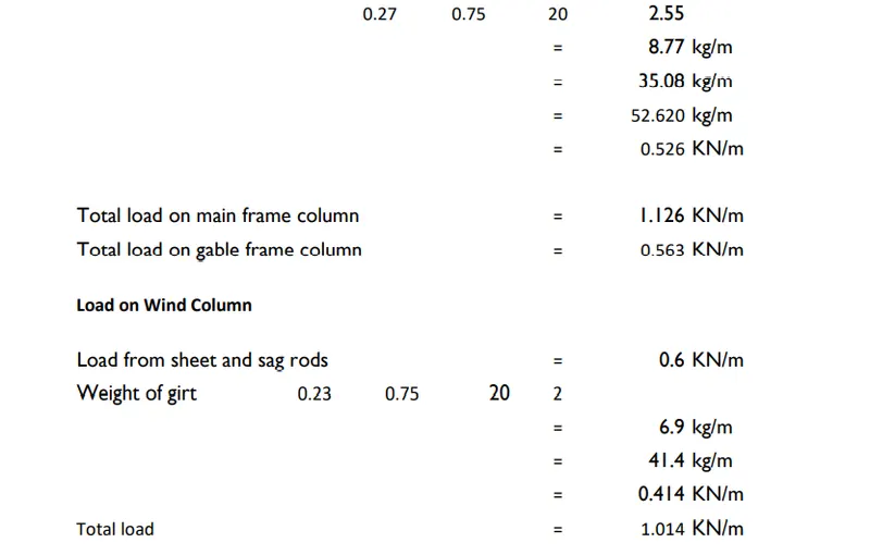
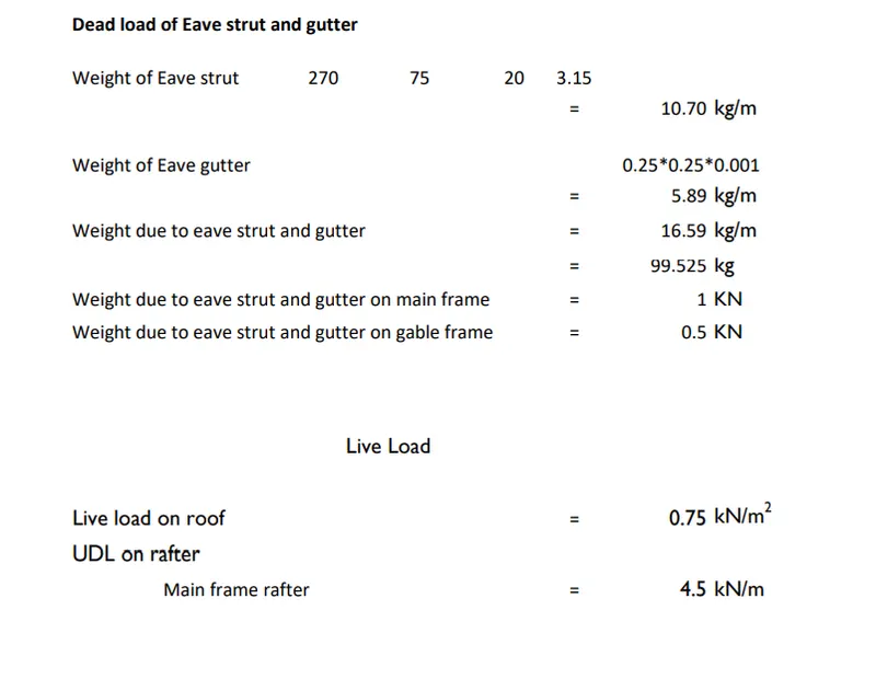
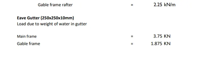
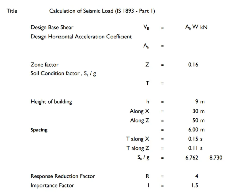
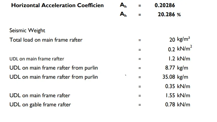
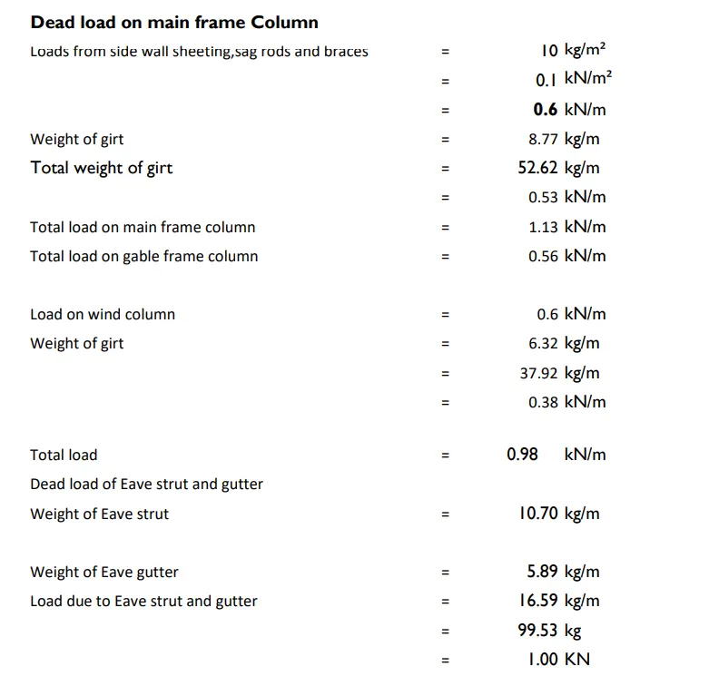
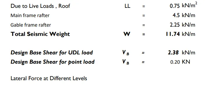
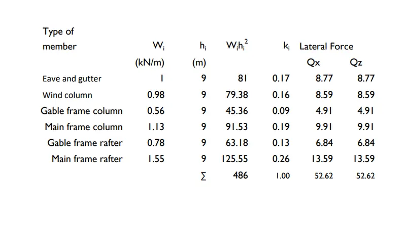
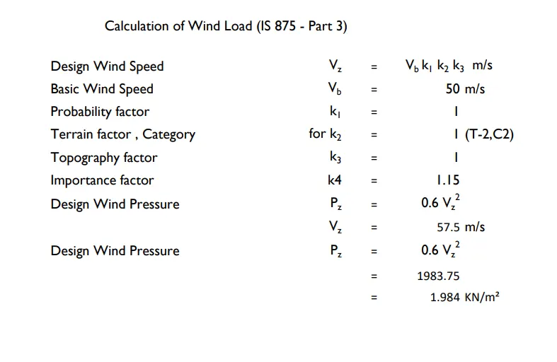
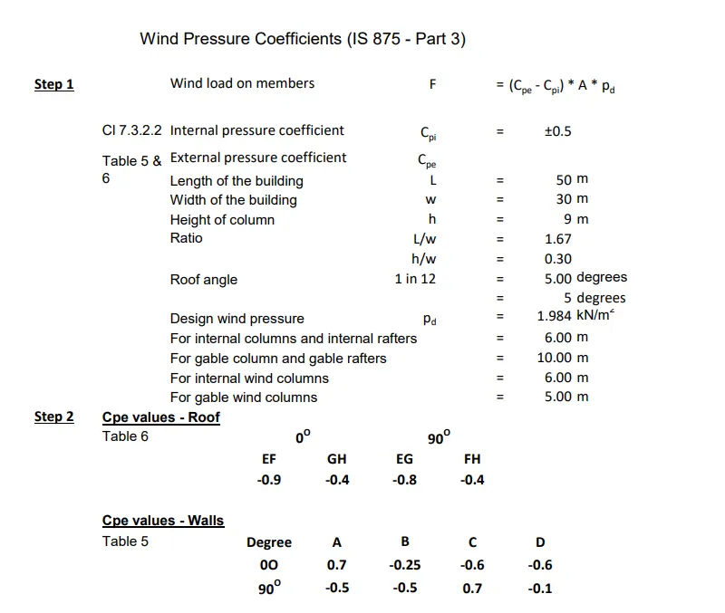
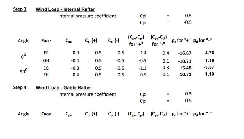
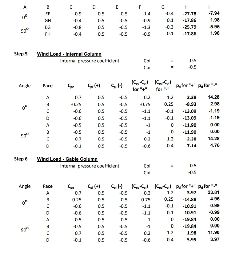
AIM-Prepare DL, LL, WL and EQL load calculations as per IS 875 standards.
INTRODUCTION-
- DL, LL, WL and EQL we can calculate manually with the use of IS Codes .
PROCEDURE-
DEAD LOAD AND LIVE LOAD CALCULATION-
Earthquake load calculation-
Wind load calculation-
Q.1D
AIM- Design warehouse building member using ms-axel.
INTRODUCTION-
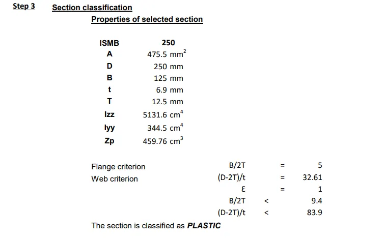
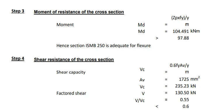
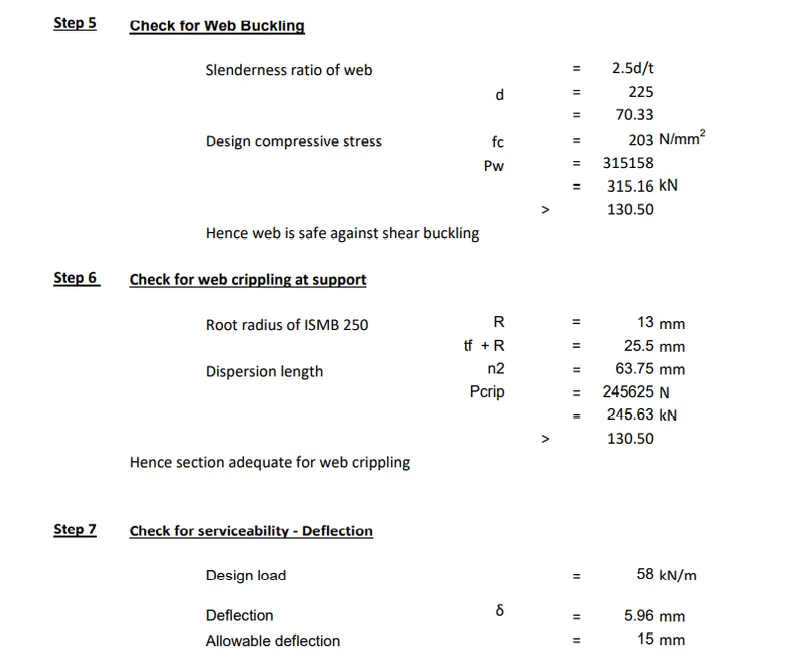
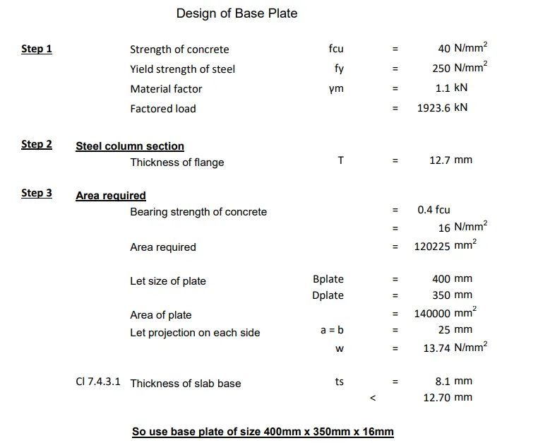
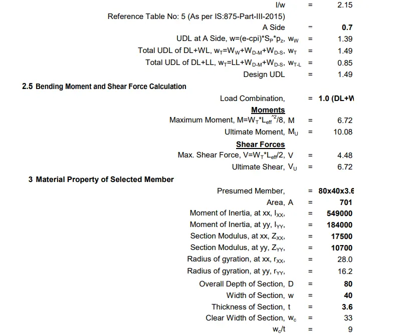
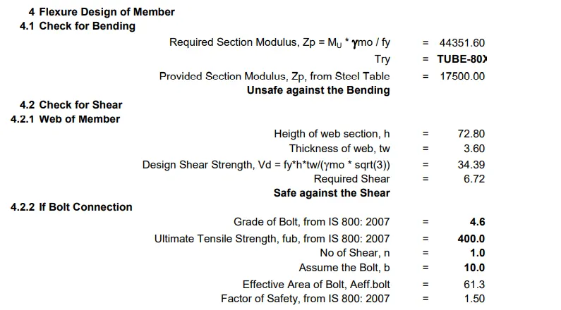
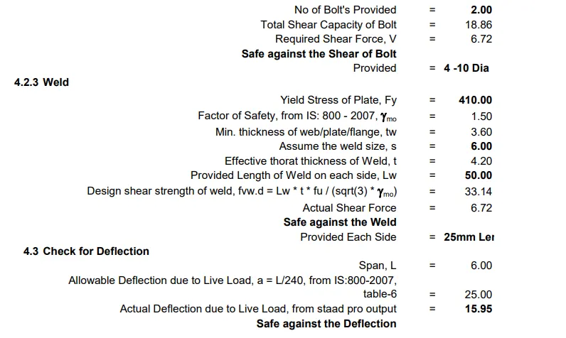
- For the point of safety against collapse of building and to fulfill the IS code criteria of serviceability we will design all member manually and will cross check all results from Staad results.
PROCEDURE-
a) Steel column Design-
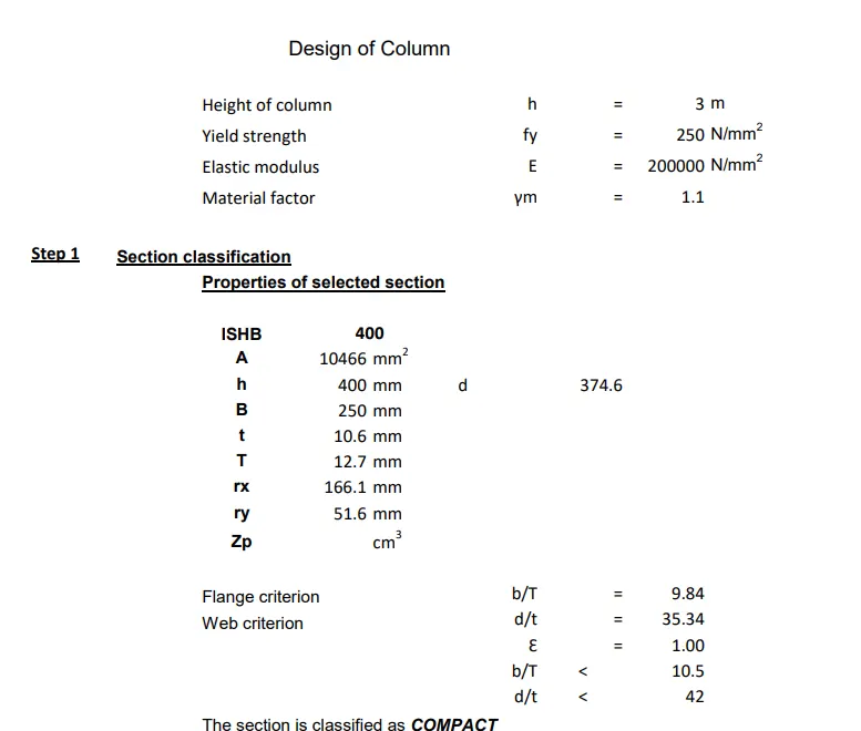
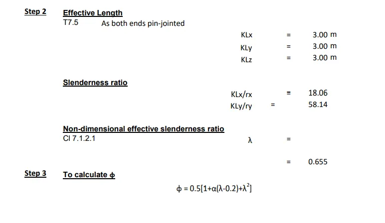
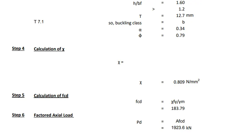
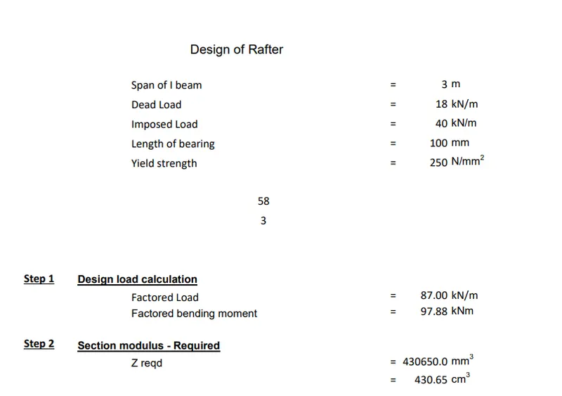
b) Design of rafter-
c) Design base plate of column-
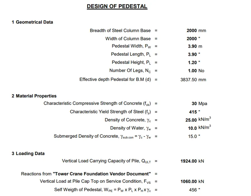
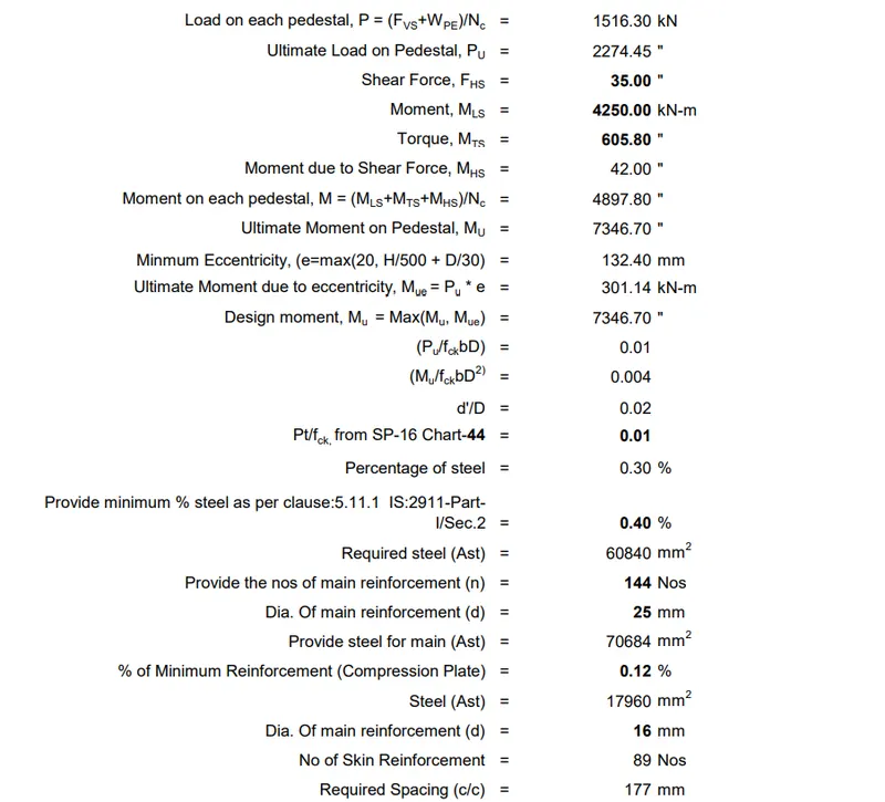
d) Pedestal design-


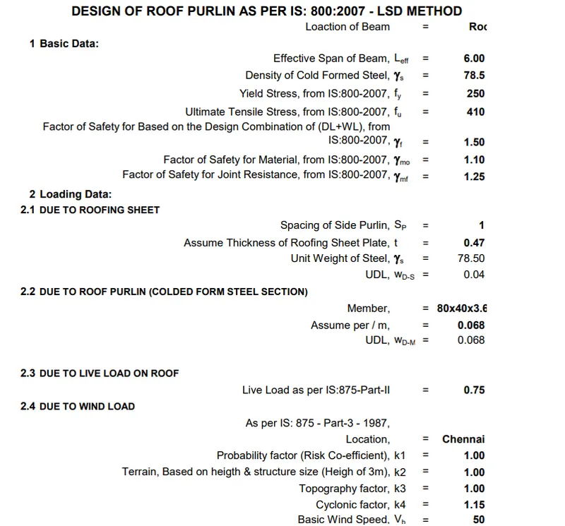
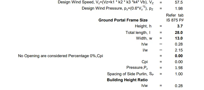
e) Z-purlin design-

Q.1
AIM-Design Foundations using STAAD Foundation.
INTRODUCTION- Foundation or footing can be design manually, with the use RCDC and with the use of seperate available tab foundation design.
PROCEDURE-
- Open staad foundation design linked software of stadd pro and click on staad foundation advance licence tab and ok.
- First setup the units under the home tab.
- Set soil properties under the load and factors tab.
- Choose the parameter of isolated footing under the Isolated footing job icon and provide all detail like SBC, depth of water table etc.
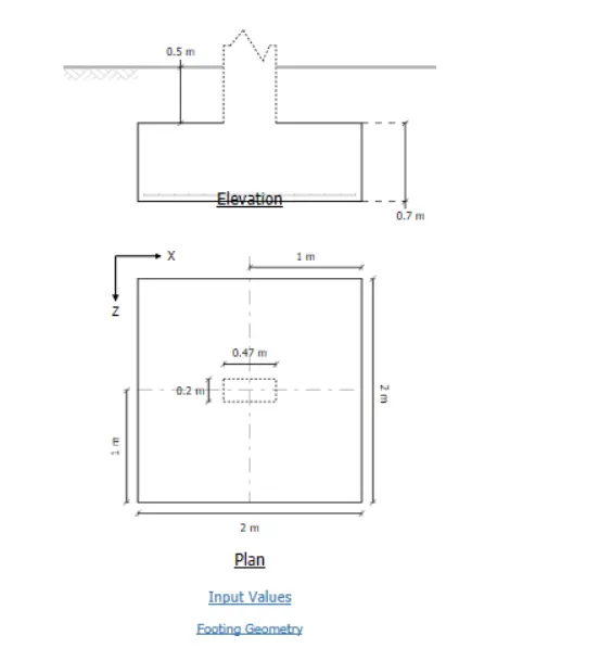
- Set the footing zeometry.
- Click on design icon and save it.
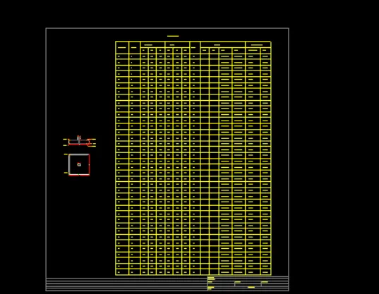
- Under the startpage we able to see drawing like Detail schedule drawing, General arrangement drawing.
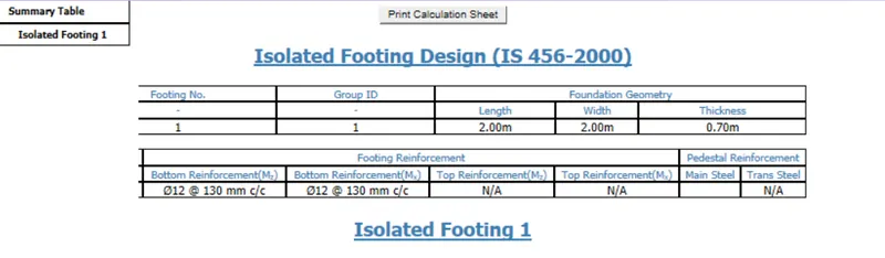
- We can also see here calculation sheet of footing.
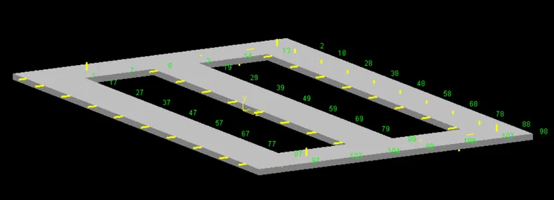
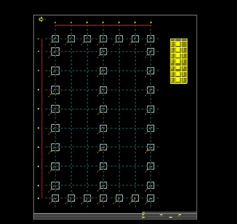
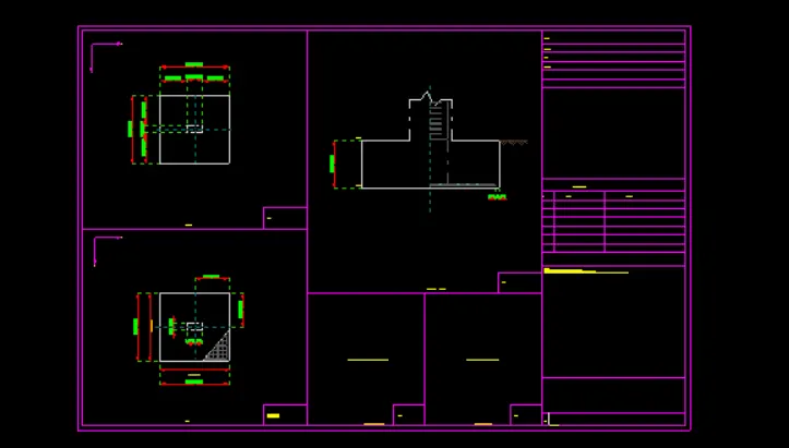
General arrangement of foundation-
CALCULATIONS-
foundation schedule drawing-
FOUNDATION DEATAIL DRAWING-
RESULT-
Foundation design software which is attached to the staad pro gives us to design any foundation and we able to extract all result in pdf or in other format.
Q.2
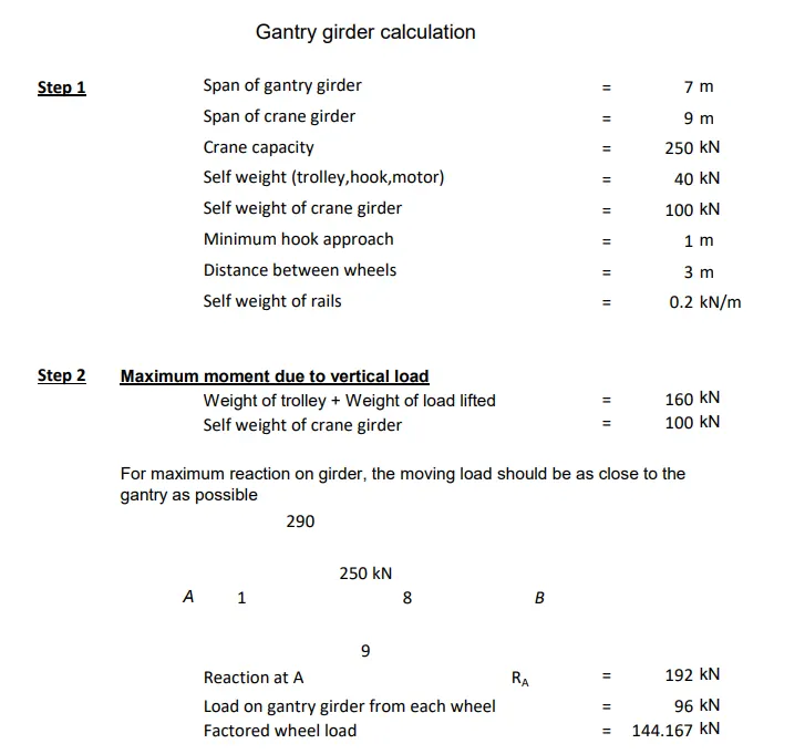
AIM-Design a simply supported gantry girder to carry electric overhead travelling crane
Given:
Span of gantry girder = 7 m
Span of crane girder = 9 m
Crane capacity = 250 kN
Self-weight of trolley, hook, electric motor etc. = 40 kN
Self-weight of crane girder excluding trolley = 100 kN
Minimum hook approach = 1.0 m
Distance between wheels = 3 m
Self-weight of rails = 0.2 kN/m
INTRODUCTION-
- Gantry girders are used to lift or to transport the goods and
equipment from one place to another place in the workshop. - Gantry Girders are typical example for laterally unsupported
beam in industrial buildings. - Also Gantry Girders undergo bending moment under both the
direction. one is vertically and other is laterally. - So biaxial bending movement has to be also checked for design
of Gantry Girders.
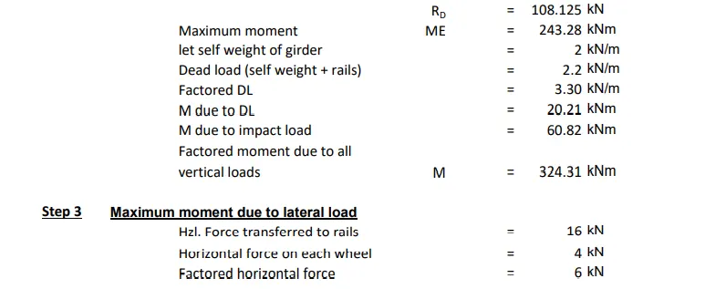
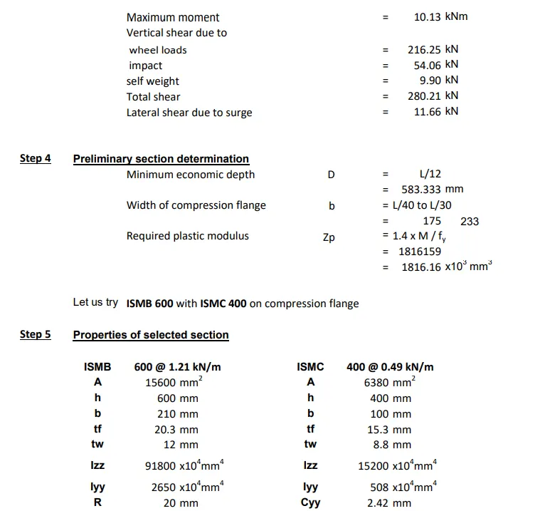
PROCEDURE-
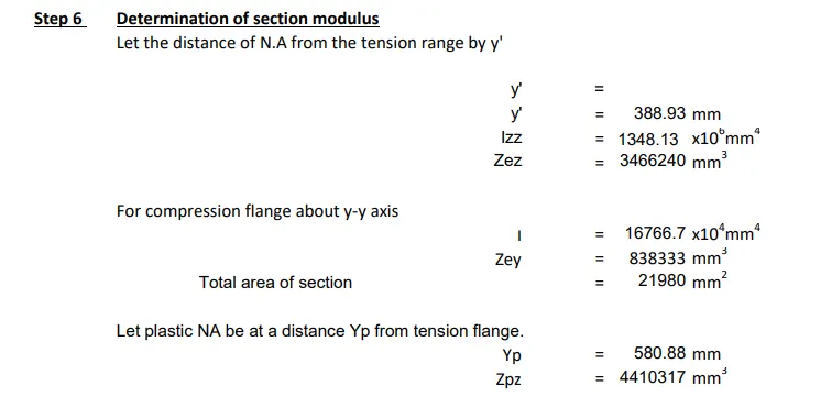
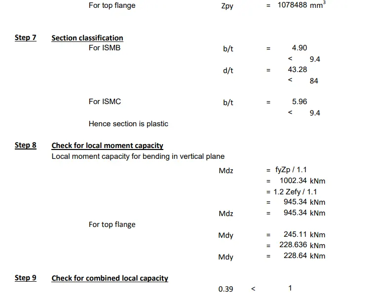
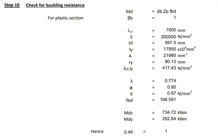
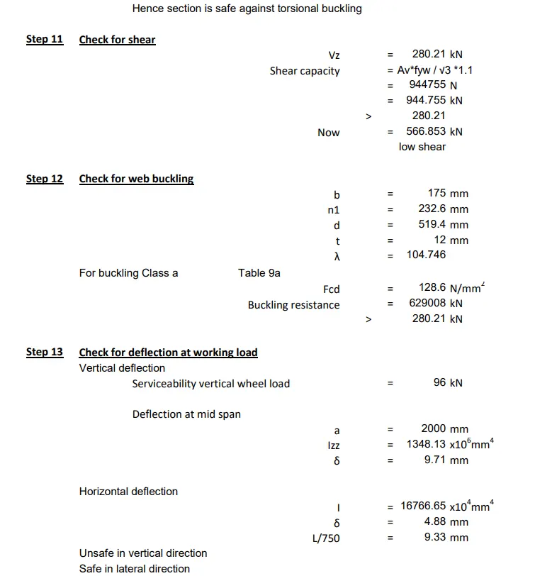
RESULT-
Gantry girder designed with all necessary check and checked for deflection here it is unsafe in vertical direction but safe in horizontal direction, so for safety against vertical deflection we will choose the another section.