Project 2
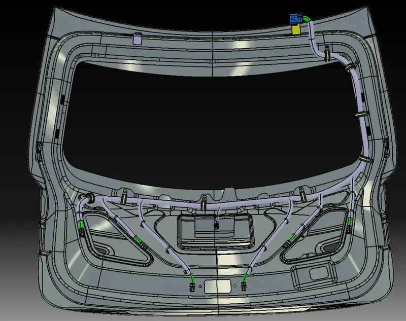
Aim: Routing the Wiring harness on the Given car body and Preparing flattened view drawing in CATIA V5 along with the protection covering
Assumptions:
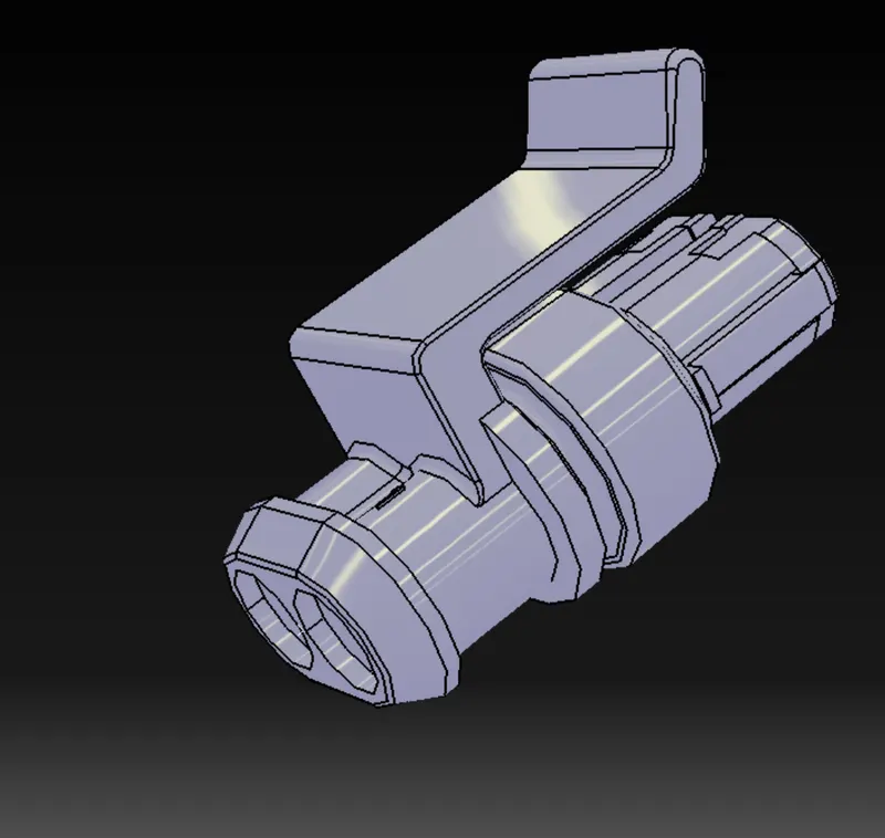
- For the two tail lights and two indicators, a total of four 2-pole connectors have been used.
- For the number plate two 2-pole connectors have been used.
- For the parking sensor one 2-pole connector has been used.
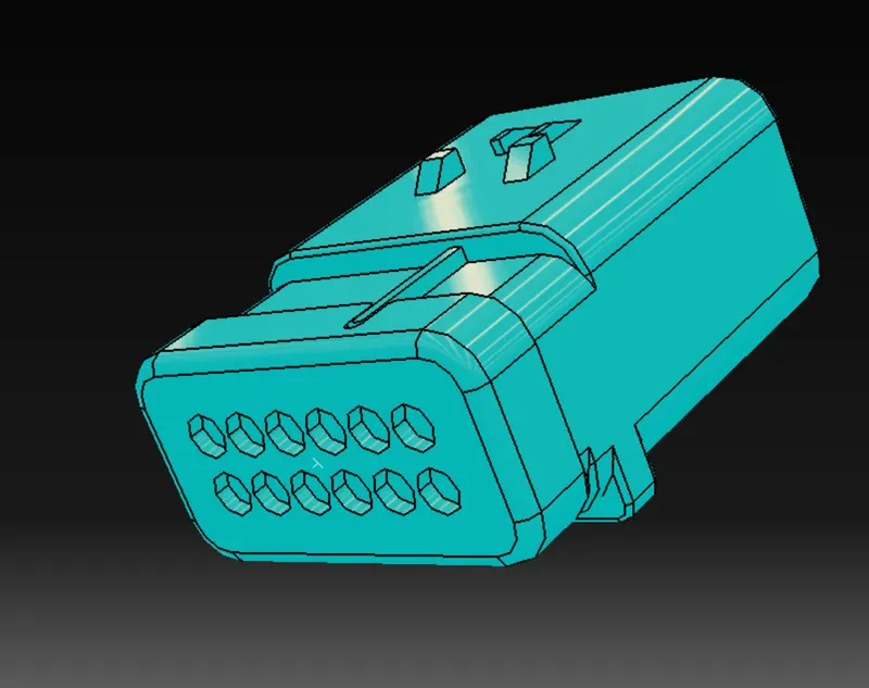
- For the wiring harness connection between the car body and back door an interconnection connector has been used, a 12-pole connector.
- For the mounting parts, clips/clamps were used wherever necessary. Also, in order to mount the clips/clamps we are assuming that holes are already present in the required positions. The location and size of the holes are later conveyed to the manufacturing and design team.
Assumed components used :
Interconnection connector
2-Pole connector:
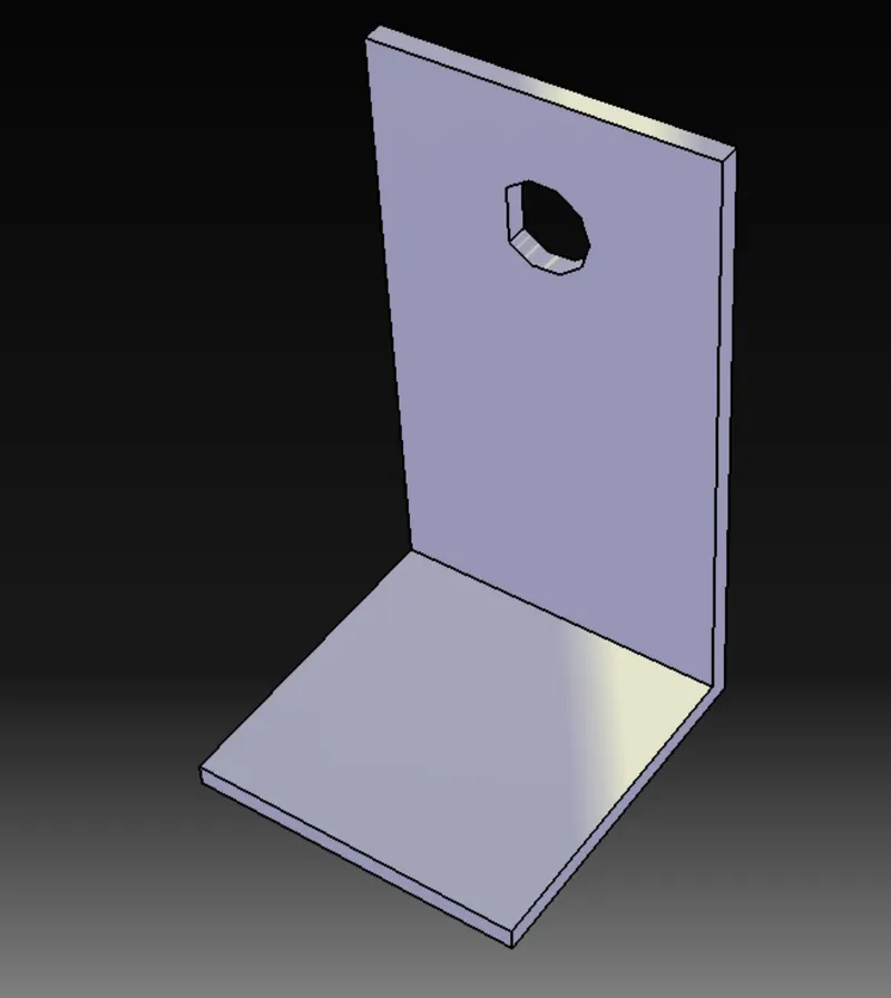
L-clip:
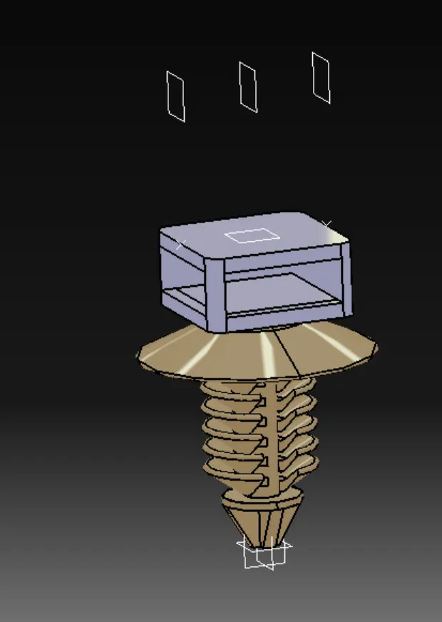
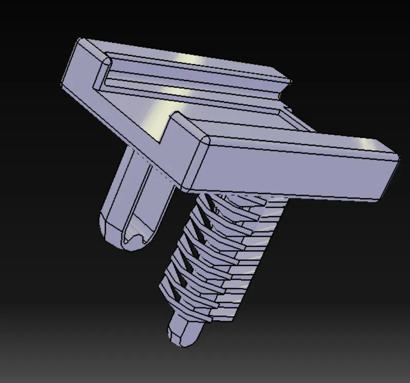
Fir tree clip:
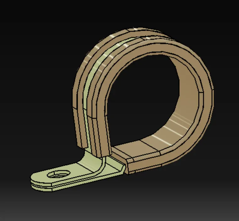
P-clamp:
Cavity Clip:
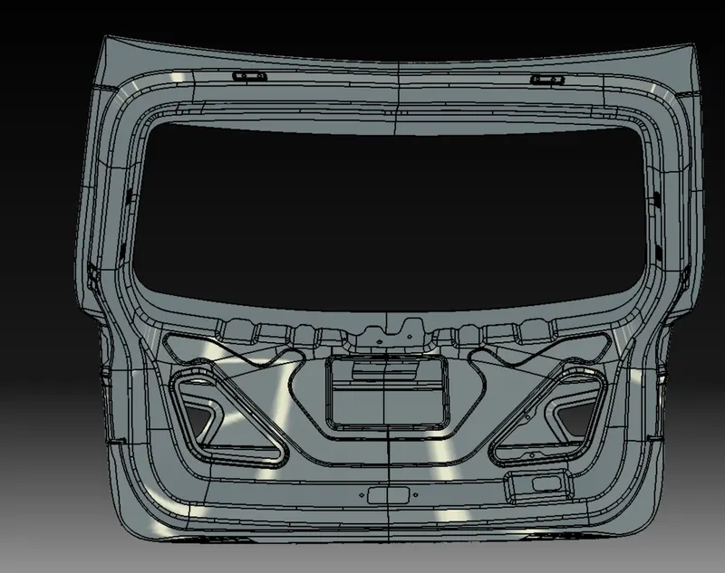
Downloaded Back Door CAD Model:
Steps Involved:
- Engine backdoor CAD was downloaded and imported into CATIA mechanical assembly workbench.
- All the required components were defined electrically and were stored in a catalog so that parts can be called with much ease whenever required.
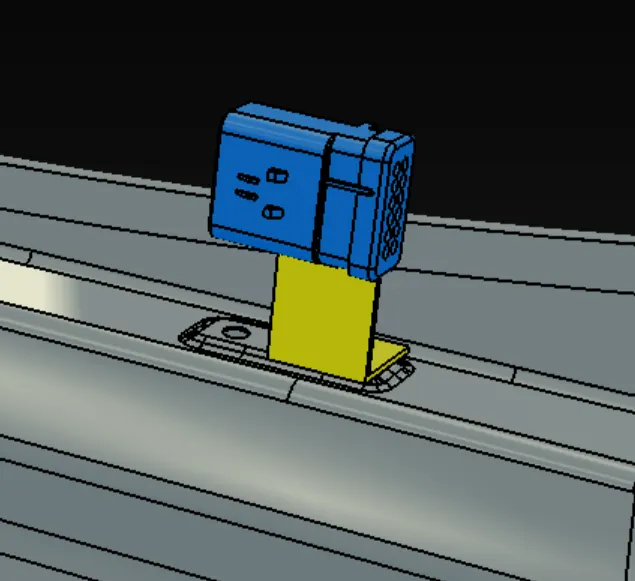
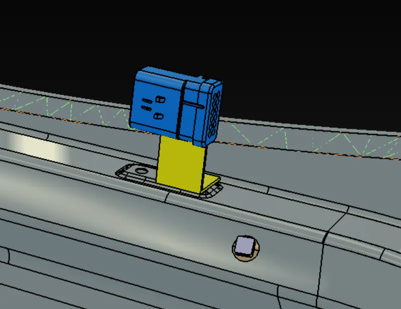
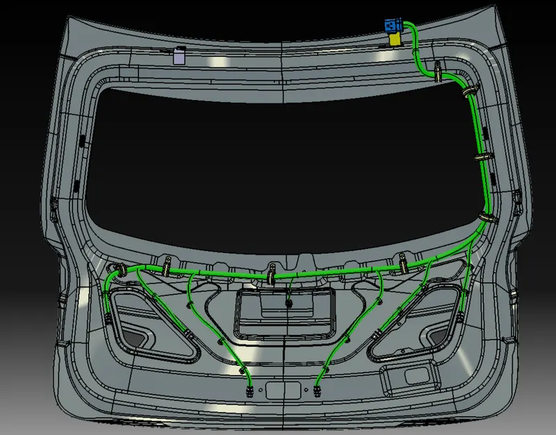
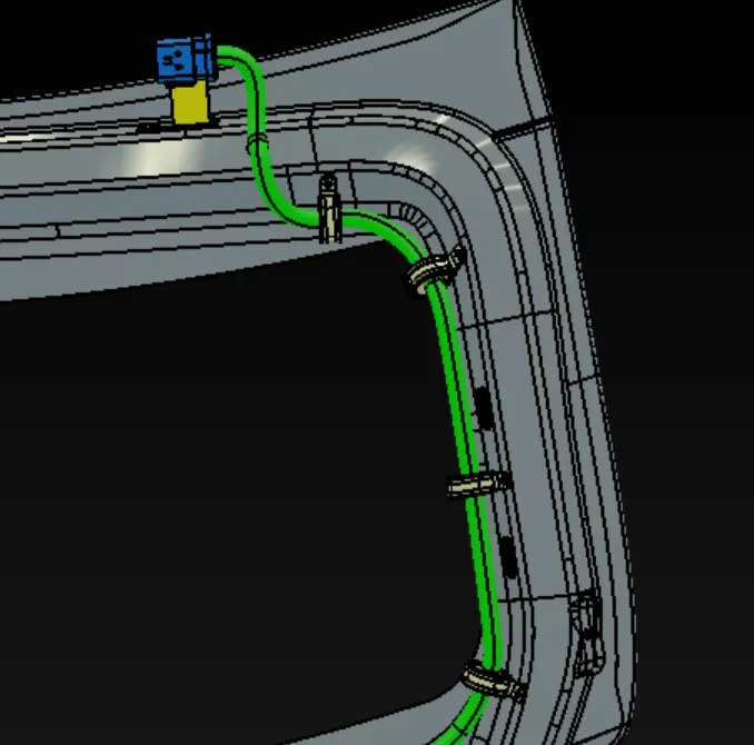
- First of all, the interconnection connector was mounted on the backdoor using an L clip on the top right of the door.
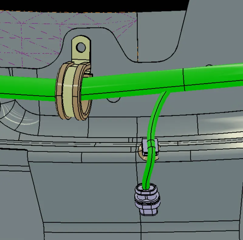
- Next a fir tree clip was placed as shown.
- And then the P-clamps were placed as shown:
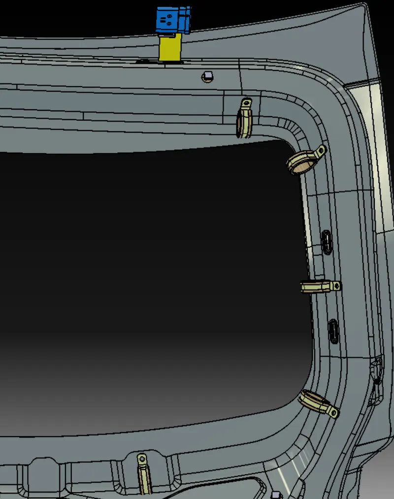
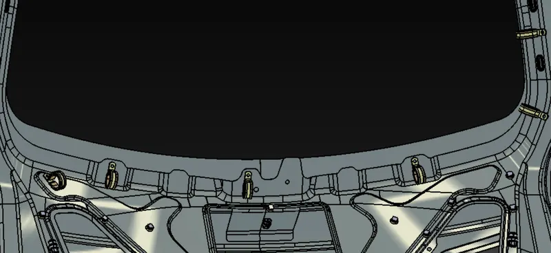
- Conne
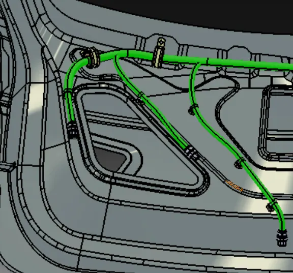
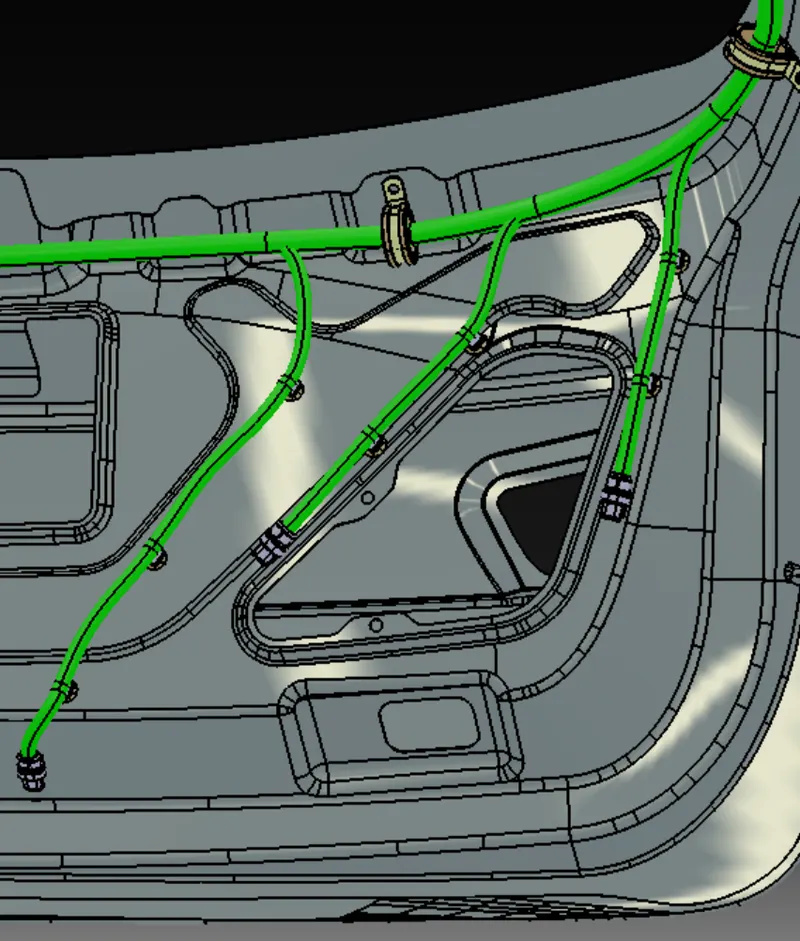
- Additionally, more fir tree clips were used for connecting the connectors with the main branch.
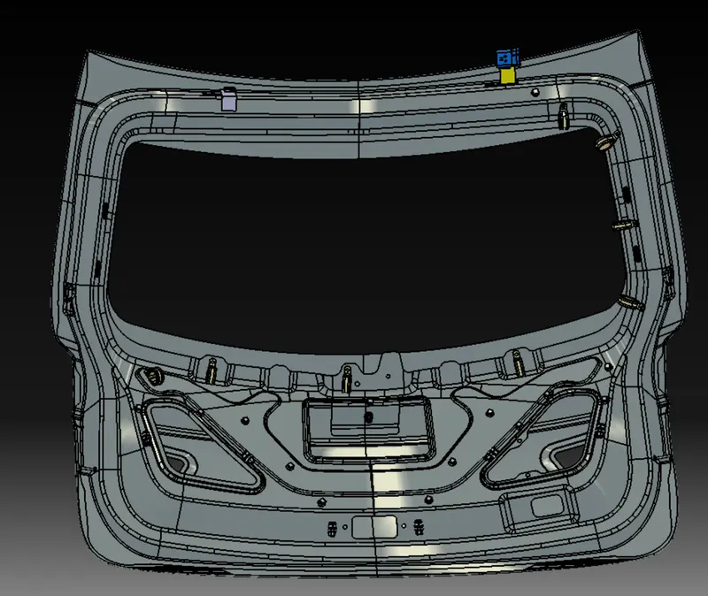
- The P-clamps were used for the straight routing of the bundle while the fir tree clips were used for creating offset, as well as curved and precise routing of the sub-branch bundles.
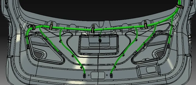
- The connectors connecting with the lights and sensor were placed in the required positions.
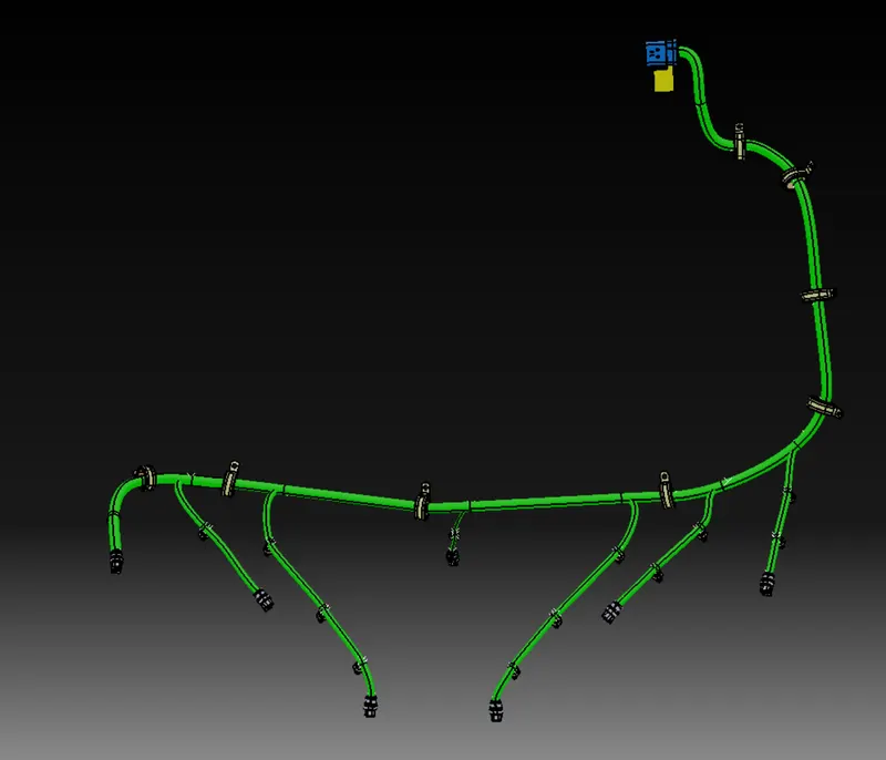
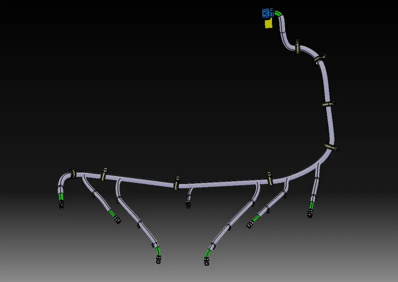
- Then routing was done starting from the interconnection connector to the left-most connector adjacent to the left tail light as seen from the inside. This was the main branch with a bundle diameter of 15 mm.
- And then the rest of the connectors were connected with the help of branch point creation and fir tree clips. These subbranches have a bundle diameter of 10 mm.
- The subbranch connecting the sensor connector has a bundle diameter of 5 mm.
Sensor connector :
Checking Bundle Continuity:
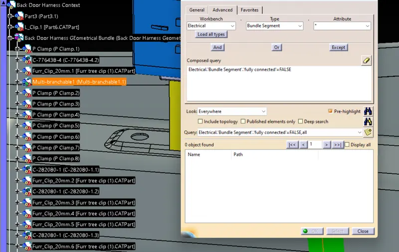
- Now the entire bundle was checked whether it was fully connected or not.
- Multi-branchable was selected then Edit>Search>Advanced>
Workbench-Electrical>Type- Bundle Segment>Attribute-Fully Connected - Now by selecting False, it showed 0 objects found, which means every bundle segment is fully connected.
Applying the protection covering:
- Cot Tubes were provided to the bundles depending on the diameter.
- End extremity clearance was taken as 30mm from the connector end.
- Only for the subbranch connecting the sensor, the end extremity clearance was set as 15 mm.
Creating a flattened view:
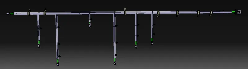
- Flattening parameters: 'Single line' for bundle segment and 'Double' line for protective covering.
- Fattening file was saved in the same folder where other harness assembly files of were saved.
- The Harness assembly was imported into the Electrical Harness Flattening Workbench.
- The assembly flattened the file along the face of the interconnection connector
- After applying the flattening, some required changes were done using the rotate command. And also changes were made inside the Mechanical Assembly Workbench like rotating the clips/clamps and the connectors for proper view.
Drawing Sheet:
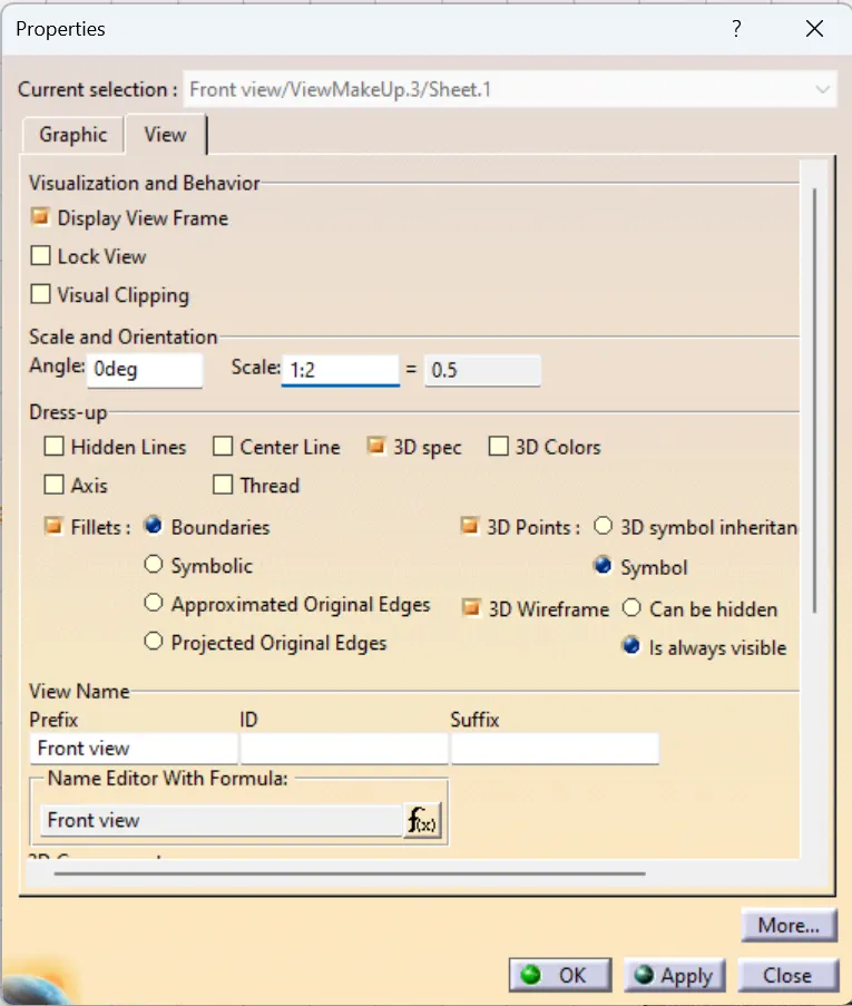
- The Harness Flattening file was imported into the Drawing with sheet parameters: A0 ISO landscape
- And the following properties were checked:
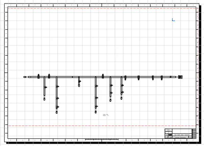
Routing Assumptions:
- Clips/clamps were provided as per requirement.
- it was made sure that there is no fouling case/ interference of two similar or dissimilar components while designing the wire harness.
- Additional clips/clamps may be used to avoid fouling.
- Routing over the bolt and bolted joints were avoided to avoid harness puncture.
- Routing on sharp edges was avoided or else protection over the harness was provided.
- Additional slack was given wherever needed(5-10% )
- The harness was kept away from heat generation components. Protection was provided according to the surrounding temperature.
- Avoid direct support for harnesses on fuel lines routed in the engine.
- It is not recommended to mount anything with the manifold mounting bolts
- Branch length was greater than 50mm.
- Minimum distance between two branch points was at least 50mm.
- Minimum distance between clip and branch was at least 25mm.
- Too many sheet metal brackets on the engine were avoided. (Try to use available threaded bosses on the engine or demand for it.)
- The wiring harness should be easy to assemble and easy to access.
- While using dummy connectors, ensure that whatever positions we are defining are practical.
Conclusion:
The Electrical Wiring Harness Assembly of a car Backdoor was succesfully created without any fouling/interference along with a flattened view and a 2d drawing sheet of the same, all the components have been electrically defined and have been added to a catalog