Project 2
Using MATLAB/simulink and the drive cycle from the attached excel sheet, find-
- The max heat generation of the battery
- The SOC of the battery at 2 *104second of the battery operation
Consider the battery resistance is 0.5 mOhm, delta time is 0.1 and entropic factor is 2.
Objective:
- The maximum heat generation of battery.
- State of charge(SOC) of the battery at 2*109sec of the battery operation.
a)
Heat generation in a battery:
Batteries also generate heat during charge and discharge due to enthalpy changes, electrochemical polarization and resistive heating inside the cell [2, 3]. Temperature variation inside the batteries can lead to uneven temperature distribution which creates uneven charge/discharge behaviour within the pack.
Exothermic and Endothermic:
An exothermic process releases heat, causing the temperature of the immediate surroundings to rise. An endothermic process absorbs heat and cools the surroundings.
Enthalpy ,Entropy and Joules heat:
Enthalpy is the sum total of all the energies, whereas entropy is the measure of the change in enthalpy/temperature.
Joule heating, also known as resistive, resistance, or Ohmic heating, is the process by which the passage of an electric current through a conductor produces heat.
Heat generated = Joules Heat + Entropy Heat
Joule heat,
H = I^2*R*t
Where, p = Power
V = Voltage
I = Current
R = Resistance
H = Heat
t = Time
Given
Entropic factor = 2
Battery resistance = 0.5 mOhm = 0.0005 Ohm
Maximum current = -0.896 A
Maximum time = 2.0 min
Calculations:
Maximum joule heat = I^2 *R*t
= (-0.896) ^2*0.0005*2
= 0.000802816
Maximum heat generation in the battery pack = joule heat + Entropy heat
= 0.000802816 + 2
Maximum heat generation in the battery pack = 2.000802816
b)
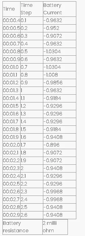
| Battery resistance | 2 milli ohm |
| Time | Time Step | Battery Current |
| 00:00.4 | 0.1 | -0.9632 |
| 00:00.5 | 0.2 | -0.952 |
| 00:00.6 | 0.3 | -0.9072 |
| 00:00.7 | 0.4 | -0.9632 |
| 00:00.8 | 0.5 | -1.0304 |
| 00:00.9 | 0.6 | -0.9632 |
| 00:01.0 | 0.7 | -1.0304 |
| 00:01.1 | 0.8 | -1.008 |
| 00:01.2 | 0.9 | -0.9856 |
| 00:01.3 | 1 | -0.9632 |
| 00:01.4 | 1.1 | -0.9184 |
| 00:01.5 | 1.2 | -0.9296 |
| 00:01.6 | 1.3 | -0.9296 |
| 00:01.7 | 1.4 | -0.9296 |
| 00:01.8 | 1.5 | -0.9184 |
| 00:01.9 | 1.6 | -0.9408 |
| 00:02.0 | 1.7 | -0.896 |
| 00:02.1 | 1.8 | -0.9072 |
| 00:02.2 | 1.9 | -0.9072 |
| 00:02.3 | 2 | -0.9408 |
| 00:02.4 | 2.1 | -0.9296 |
| 00:02.5 | 2.2 | -0.9296 |
| 00:02.6 | 2.3 | -0.9968 |
| 00:02.7 | 2.4 | -0.9968 |
| 00:02.8 | 2.5 | -0.9408 |
| 00:02.9 | 2.6 | -0.9408 |
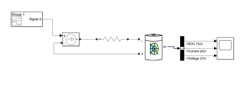
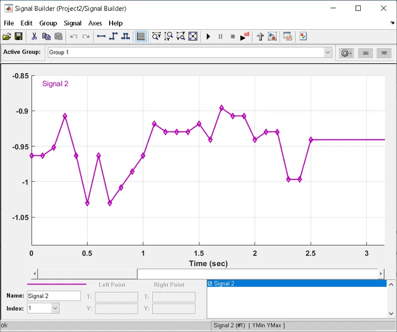
- The signal buider is given as the input to the model.
- Here the drive cycle stop time is 2*104 i.e 208sec
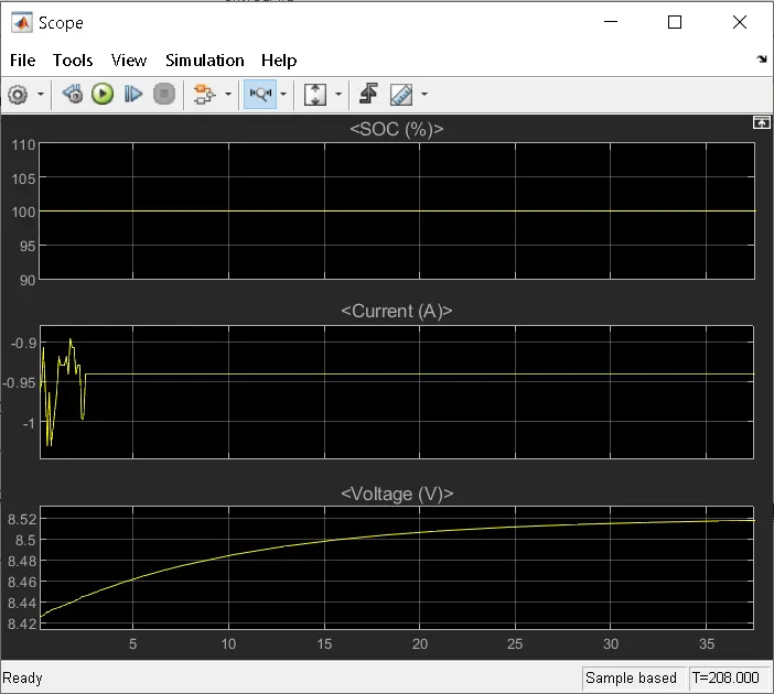
- so the simulation run time is 208sec
- Here the output of the signal buider is given to the current controlled source which is connected to the battery as a load
- so here the battery is dicharged accroding to this siginal given by the data.
- Here the power gui block is rquired for any simulation of the simulink model.
- It mainly used to store the equivalent simulink circuit which represents the state space model.
- The ouput of a battery is given to the scope through the bus selector the bus selector outputs the battery siginals to the scope