Project 2
1. From the grillage model for I-Girder (Longitudinal Analysis of 3 X 25 Meter Prestressed I-Girder) modeled in project 1 extract the reaction and answer the following Question.
Ans:
Staad Model:-
- A three girder system of 3 x 25m is to be created .
- First of all a node is created and then the width of the deck slab has been created with 2m spacing each.
-
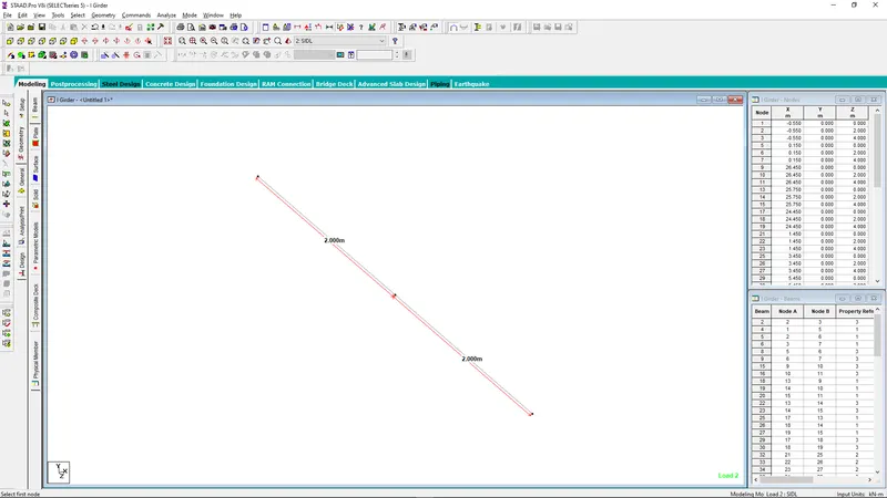
- Then the over hang portion of the bridge has been created at -ve X-direction at a distance of 0.7m as given.
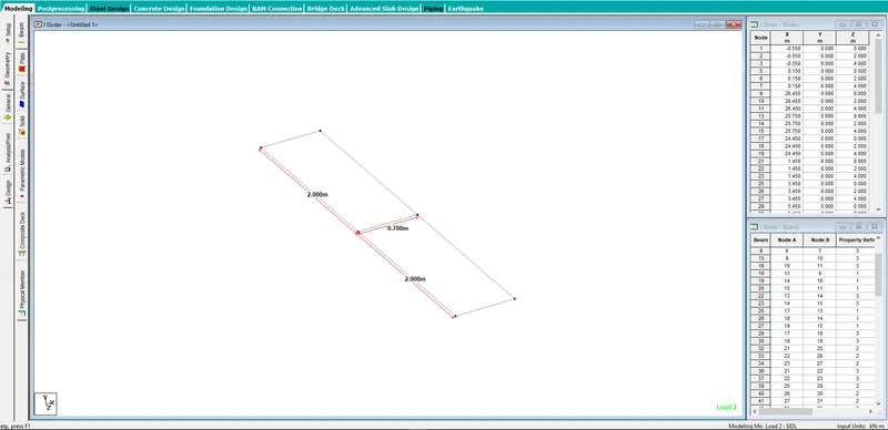
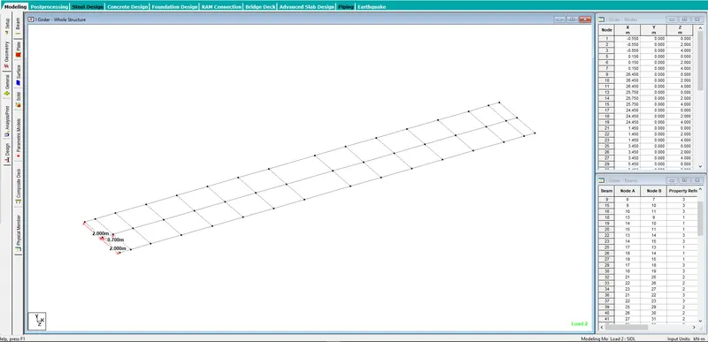
- Then accordingly the whole structure has been created in both the sides.
- Then diffrent type of Supports considering the functional behavoiur of bearings for the model need to be created.
- The support releasing the Mx, My & Mz has been created.
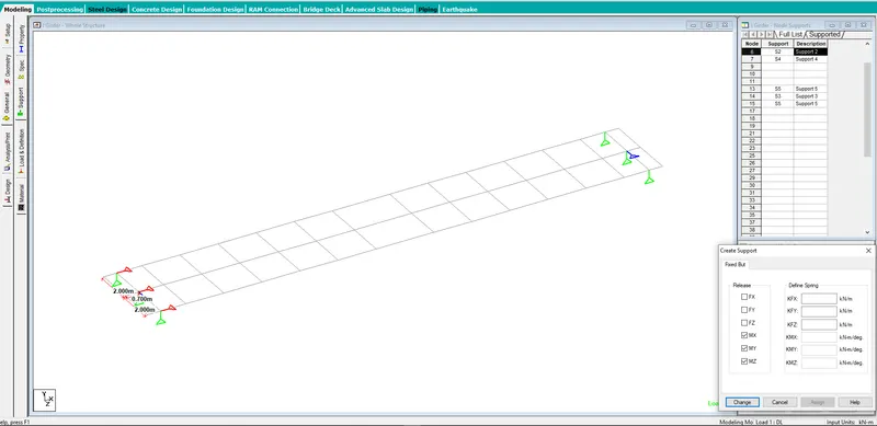
- The support releasing the Mx, My, Mz & Fx has been created.
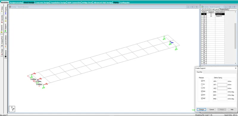
- The support releasing the Mx, My, Mz & Fz has been created.
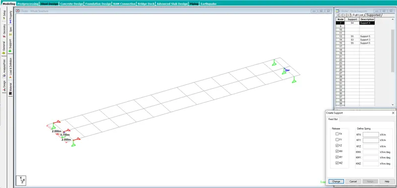
- The support releasing the Mx, My, Mz, Fx & Fz has been created.
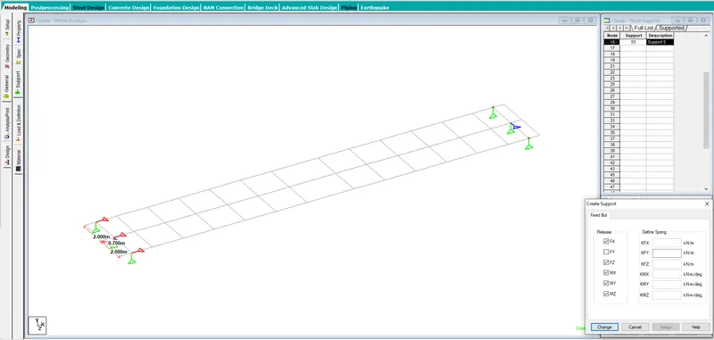
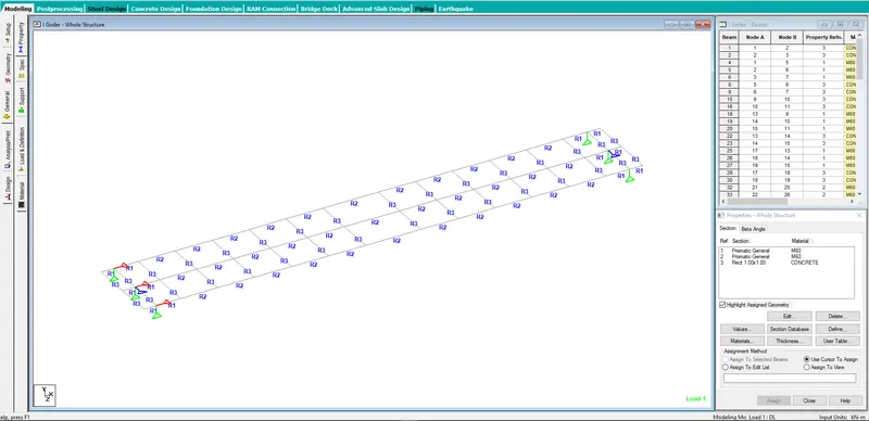
- The supports to the respective bearing positions has been assigned.
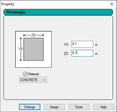
- Material Property
- The material property as given has been created.
- For End Section
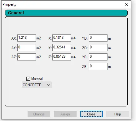
- For Mid section
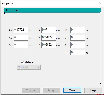
- Material property for cross girder has been created as dummy member.
- The properties has been assigned to the structure as described.
- Loads & Definations
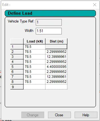
- Vehicle definations created.
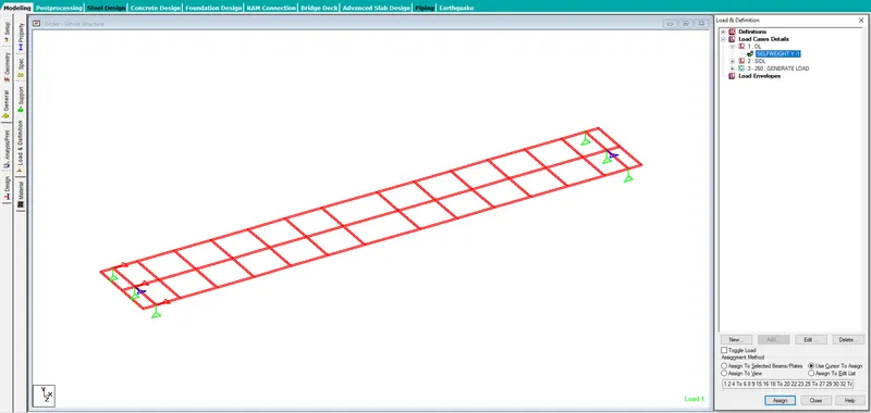
- Self weight has been defined with a factor of -1 & applied to the whole structure.
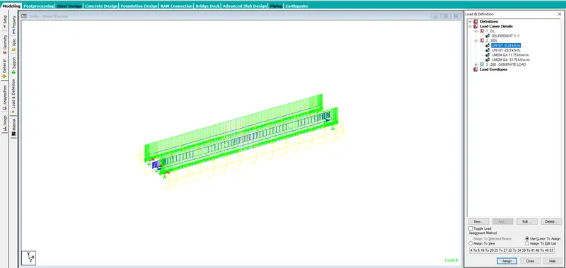
- Different loads as SIDL for wearing coat has been defined and assigned to the intermediate girders
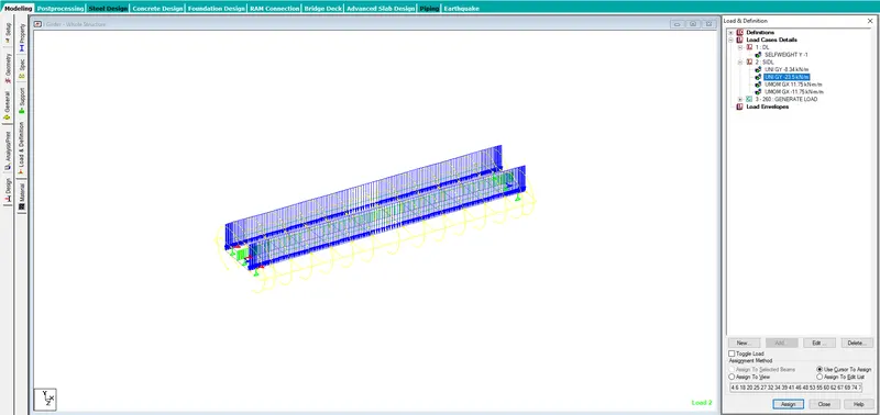
- SIDL for crash barrier loading has been created and assigned to the end girders.
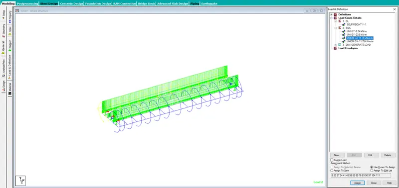
- Moment due to SIDL eccentric loading is to be applied. Moments at the intermediate girders has been applied in both the global x direction.
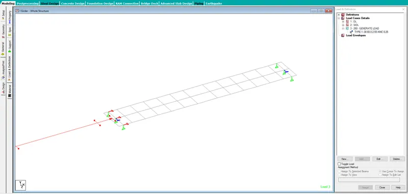
- vehicles Loads has been generated considering the length of the boggie and the length of the span. Also considering the intervals at 0.25.
- Single trains is being considered as per the with of the structure.
- Material Property
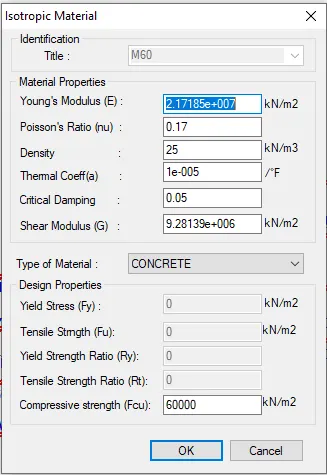
- New material for M60 and dummy member has been defind with the following inputs.
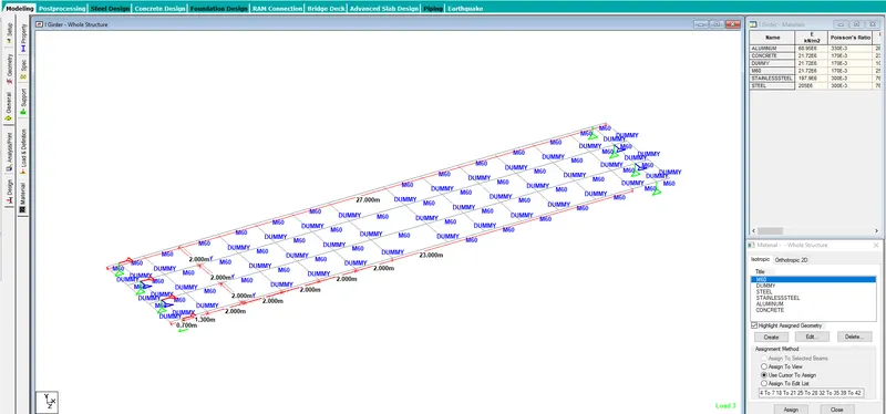
- Property M60 and dummy has been assigned to the model.
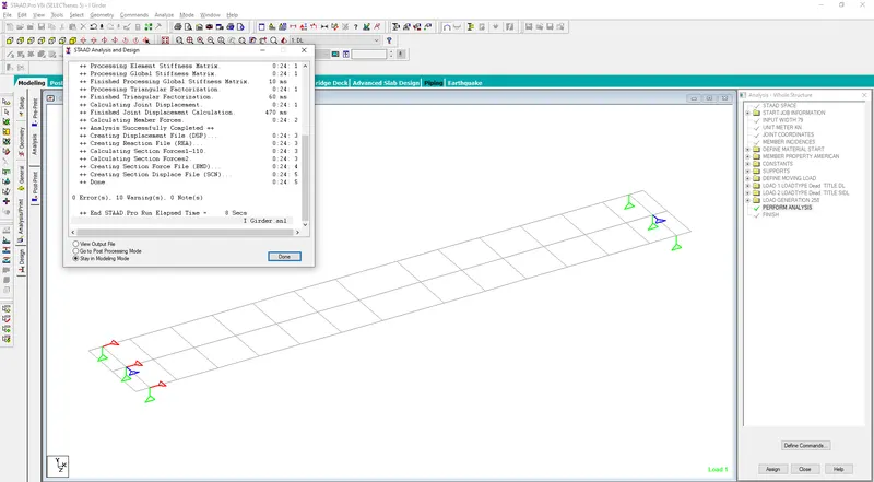
- The model has been analyzed and results with 0 error.
- Results
- Max deflection of the struture with summary sheet.
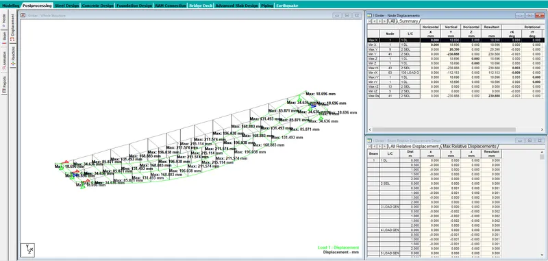
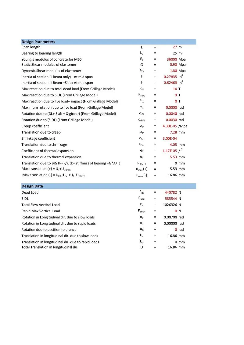
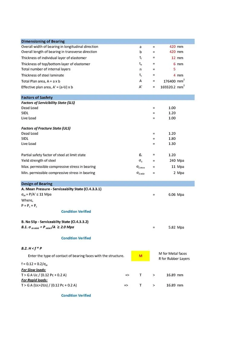
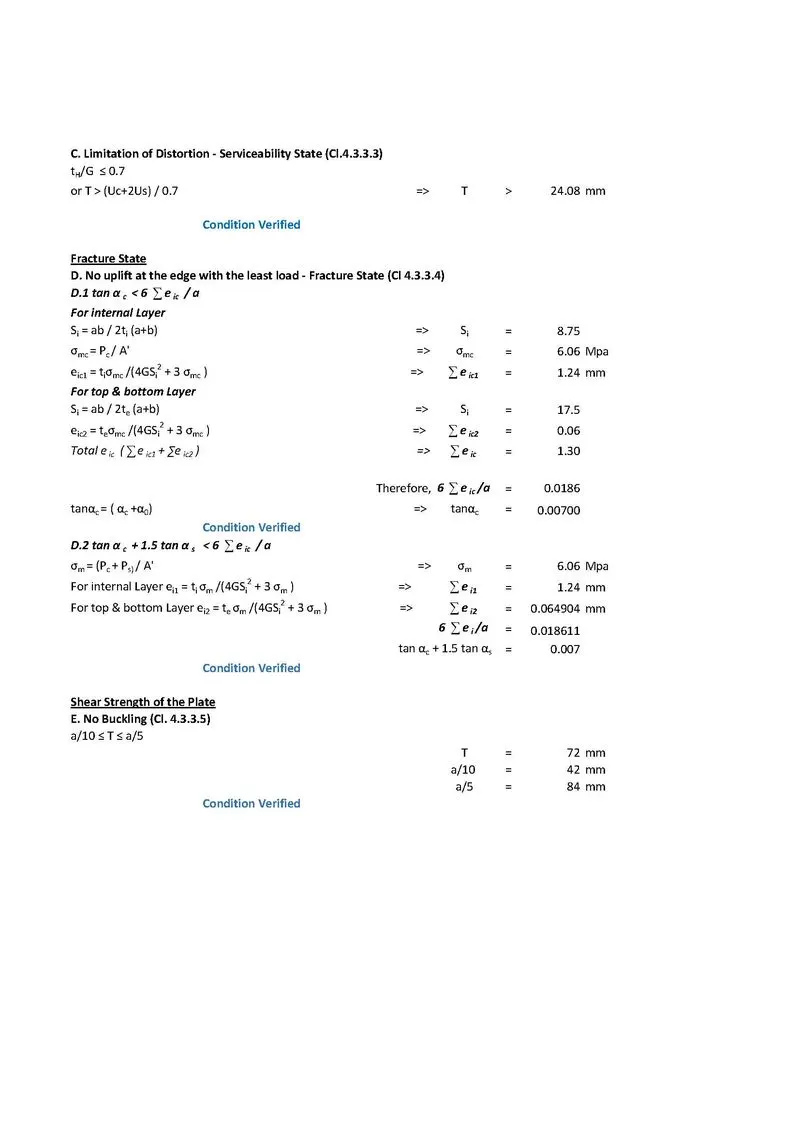
- Reactions with summary sheet.
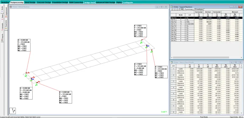
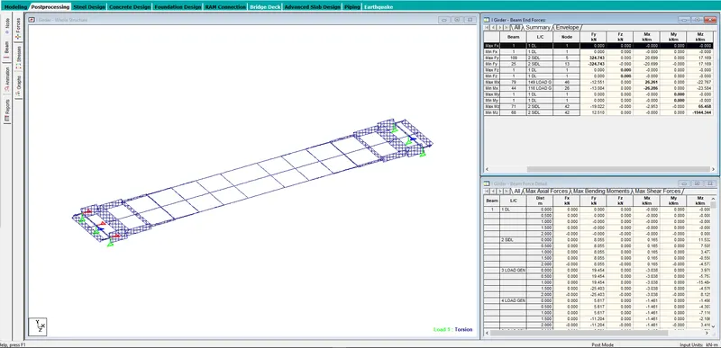
- Value of Mz with summary sheet.
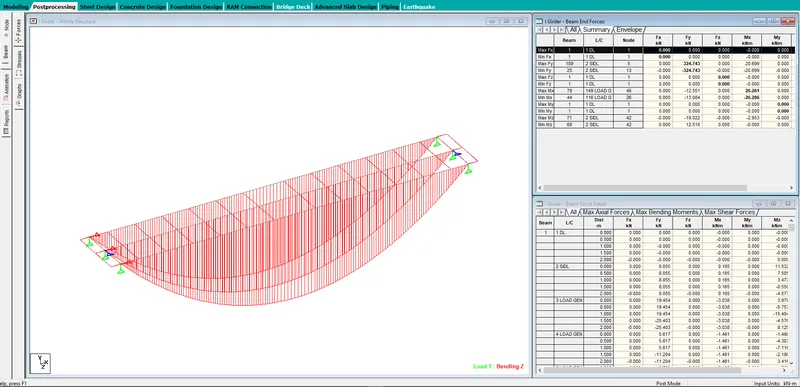
- Value of Mx with summary Sheet.
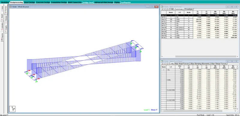
- Value of Fy with summary sheet.
Ans:
3. From the model determine the axial loads (reaction) and moments in the longitudinal and transverse direction at the base of the pier (DL, SIDL, LL). Using those values calculate the design BM and design SF for the design of the open foundation in both directions.
Ans:
- Calculating total load
DL:
Left side = 313.044 + 313.045 + 313.044 = 939.133 KN
Right Side = 313.044 + 313.045 + 313.044 = 939.133 KN
Total = 1878.266 KN = 192 t
SIDL:
Left side = 366.215 + 239.840 + 366.215 = 972.270 KN
Right Side = 366.215 + 239.840 + 366.215 = 972.270 KN
Total = 1944.540 KN = 199 t
LL:
Left side = 169.492 + 297.314 + 110.292 = 577.098 KN
Right Side = 132.883 + 136.492 + 95.528 = 364.903 KN
Total = 942.001 KN = 96 t
Wt. of Pier cap:
Considering length = 5m, Width = 1.8m, Ht. = 1.5m
Total Wt. = 2.5 x 5 x 1.8 x 1.5 = 33.75 t
Wt. of Pier:
Considering Dia = 1.2m, Ht. = 8.0m
Total Wt. = 2.5 x PI()/4 x 1.2 x 1.2 x 8 = 22.62 t
Total load (P) = 192 + 199 + 96 + 33.75 + 22.62 = 544 t
- Longitudinal Moment
The longitudinal moment for DL and SIDL will be zero as the structure is symmetric one.
Longitudinal Moment for LL = (577.098 x 0.5) - (364.903 x 0.5)
= 182.452 KN-m
- Transverse Moment
The transverse moment for DL, SIDL & LL will results as zero.
4. Calculate the load at the base of the pier - Wind, Seismic, LWR, Breaking and Centrifugal force with the following data.
Loacation of the metro viaduct - Chennai
Height of the pier = 10 M
Speed of the train = 75 km/h
Radius of curvature = 1000 m
Ans:
- Wind Force
The design wind speed at heighis considered as follows:
Vz=Vb×K1×K2×K3
Vb(m/s): Regional basic wind speed, taken 50 m/s for Chennai City
| General Parameters | ||||||
| Total Structure Height above ground | H | = | 10 | |||
| Regional Basic Wind speed | Vb | = | 50 | |||
| Probability Factor | K1 | = | 1.08 | |||
| Terrain Height & Structure size factor | K2 | = | 0.82 | Category 3 Terrain, | ||
| Topography Factor | K3 | = | 1 | |||
Design Wind Speed at Height Z,
Vz=Vb×K1×K2×K3
Vz=50×1.08×0.82×1
= 44.28 m/s
Wind Pressure,
Pz=0.6×Vz2
Pz=0.6×44.282=0.6×44.282
= 1176.44 N/m2
= 0.119 t/m2
- Seismic Load
- This load comes into play during earthquake, when the structure vibrate in the longitudinal direction.
- Live Load is not consider in the consider in this case as vibration don't have any impact on the live as it rolls away
Seismic Acceleration :- Ah = (Z/2) x (I/R) x (Sa/g) , Where:
Ah = horizontal seismic coefficient to be considered in design
Z = Zone factor = 0.16 (For Chennai)
I = Importance factor = 1.50
R = Response reduction factor
= 4 , for pier
Sa/g being computed as per IRC 6 :2017 for medium soil site
Mathematical expression are:
Sa/g = 1 + 15 T for 0.0 < T < 0.10
Sa/g = 2.5 for 0.10 < T < 0.55
Sa/g = 1.36/T for 0.55 < T < 4.00
- LWR Force
- The "Long Welded Rail" force acts on the structure due to the stresses generated in the rail.
- It is generated by the expansion/contraction of the rail due to increase/decrease in temperature.
- LWR force are consider to be 0.8 t/m/track
Longitudinal LWR force = 0.8 t/m/track for two Track
Transverse force on the pier due to LWR : F =[ΔT * α * A* E ] * [ N ] * [ L ] / R
where,
ΔT = Temperature difference = 34 degree
α = Temperature coefficient = 1.17E-0.5 per degree
A = Area of one rail = 200000 MPa
E = Elastic modulus of rail = 7670 mm2/Rail
N = Number of Rail = 3 nos
L = Span lenght, Span 1 = 25 M
Span 2 = 25 M
Radius off Curvature = 100000
Transverse force acting @ Rail Level LWR = [ ΔT * α * A * E ] * [ N ] * [ L ] / R
= [ 34 * 1.17×10−51.17×10-5 * 200000 * 7670 ] * [ 3 ] * [ 27 ] / 100000
= 45.80 Mpa
- Braking Load
- This Load comes into play when the train applies brakes while moving.
- It is taken as 18% of the unfactored vertical loads.
Consider train load as 193 T, So 18 % of 193 = 34.74 kN
- Centrifugal Force
- This load acts on curved span,
- It shall be calculated with the actual maximum allowable speed of the train in curve according to plan radius of curvature.
- Coefficient of CF = V2/127×R
Where,
V2">V2V2 is design speed of the train in km/h
R">RR is the radius of curve span in meter.
CF = V2/127×R
= 75 x 75 / (127×1000)
= 0.0454
5. Write in detail about the component of well foundations and the function of each component with relevant drawing.
Ans:
- Well Foundation
- Well foundations have their origin in India & have been used for hundreds of years for providing deep foundation to important buildings and bridges. Well foundations provide a solid & massive structure. This foundation has maximum sectional modulus for a given cross-sectional area. Wells can resist large horizontal forces & vertical loads even when the unsupported length is large in scourable river beds. A well foundation is monolithic and relatively rigid in its structural behavior.
- Components of Well FoundationA well foundation is a type of foundation which is generally built in parts at the surface and sunk to its final position, where it forms the permanent foundation. Figure below shows a typical section of a circular well foundation.
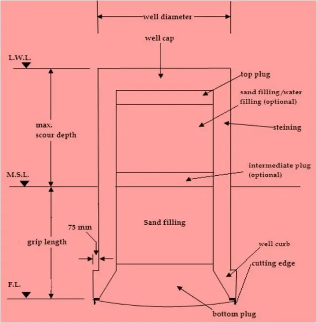
Section of Well Foundation
- Well Cap - It is a RCC slab laid at the top of the well steining to transmit the loads and moments from the pier to the well or wells below. Shape of well cap is same as that of well with a possible overhand of 150 mm all-around to accommodate lengthy piers. It is designed as a two-way slab with partial fixedity at supports. The top of the well cap is usually kept at the bed level in case of rivers with seasonal flow or at about the low water level in case of perennial rivers. Thickness of well cap is usually between 1500 mm to 2000 mm. The recommended minimum thickness is 0.75 m.
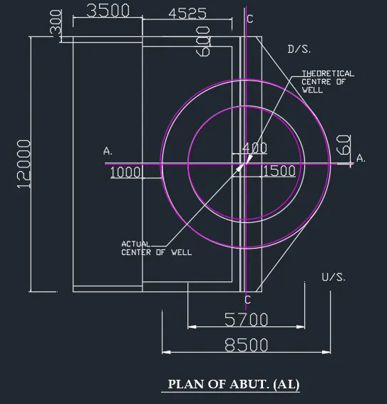
- Steining - it is the main body of the well which transfers load to the base of the foundation. Steining is normally of reinforced concrete. Minimum grade of concrete used in steining is M20 with cement content not less than 310 kg/m3. To facilitate well sinking an off-set of 75 mm to 100 mm is provided in well steining at its junction with the well curb. The steining is designed such that it can be sunk under it own weight. The thickness should be sufficient so as to overcome skin friction developed during sinking by its own weight. The minimum reinforcement in the well staining should be 5 to 6 kg/m3 of which 75 % is to be provided as vertical and 25 % as lateral ties or hoop rings. The minimum thickness is 0.45 m or 1/ 8 of the external dia. of well for brick masonry and 1/10 for wells with cement concrete. The thickness is increased by 12 cm per each 3 m depth after sinking the 3 m of steining for brick well and 15 cm for each 6 m depth after sinking the first 6 m of cement concrete well.The thickness of well steining should not be less than 450 mm nor less than that given below.
t = KD*(L1/2)
Where,
t = minimum thickness of concrete steining, m,
D = external diameter of circular well or dumb bell shaped well or smaller plan dimension of twin D well, m,
L = depth of well in m below L.W.L. or top of well cap whichever is greater,
K = a constant depending on the nature of subsoil and steining material (taken as 0.30 for circular well and 0.039 for twin – D well for concrete steining in sandy strata and 10% more than the corresponding value in the case of clayey soil).
The recommended thickness is:
D(m)
3
5
7
t(m)
0.75
1.20
2.00
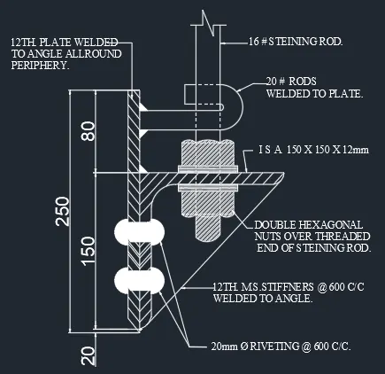
- Well Curb - It is the wedge shaped RCC ring beam located at the lower portion of the well steining provided to facilitate sinking. Well curb carries cutting edge for the well and is made up of reinforced concrete using controlled concrete of grade M25. The cutting edge usually consists of a mild steel equal angle of side 150 mm. In case blasting in anticipated, the outer face of the well curb should be protected with 6 mm thick steel plate and the inner face should have 10 mm thick plate up to the top of the curb and 6 mm plate further up to a height of 3 m above the top of the curb. The minimum reinforcement to be provided is 72 kg per cubic meter. The inner portion of the steining should have a slope of 2:1 (V:H). guidance. The internal angle of the curb should be kept at about 30 to 37.
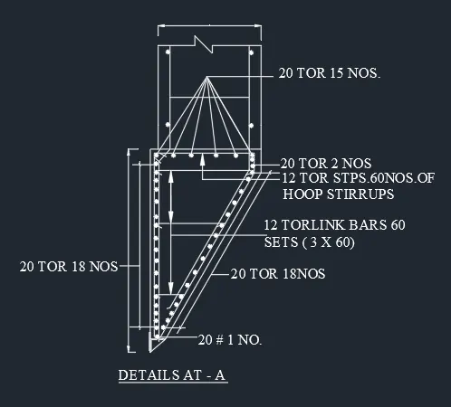
- Cutting Edge - The cutting edge is either projected below the curb as a sharp edge or can also have flat bottom. The projected edge is likely to be damaged in strata of gravels and boulders. In such soils the flat bottom cutting edge is provided.
- The mild steel cutting edge shall be strong enough and not less than 40kg/m to faciIitate sinking of the Well through the types of strata expected to be encountered Without suffering any damage.
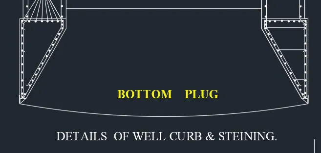
- Bottom Plug - The bottom plug is made bowled shape in order to have an arch action. The bottom plug transmits load to soil below. When sunk to its final depth bottom part is concreted to seal the bottom completely. The thickness varies from ½ to full inside diameter of the well so as to be able to resist uplift forces. The concreting should be done in one continuous operation. When wells contain more than one dredge hole all should be plugged to the same height. If the well is to rest on rock, it should be anchored properly by taking it 25 cm to 30 cm deep into rock The bottom plug should be of rich concrete (1:2:4) with extra 10 % of cement.
- The concrete mix used in bottom plug shall have a minimum cement content of 330kg/m3 and a slump of about 150mm to permit easy flow of concerete through termie to place fill up all the cavities.
- Thickness of bottom plug should not be less than the half of dredge-hole diameter nor less than the value calculated using following formula.
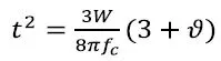
Where,
W = total bearing pressure at the base of well,
fc = flexural strength of concrete in bottom plug, , and,
ϑ = Poisson’s ratio for concrete, 0.18 to 0.20.
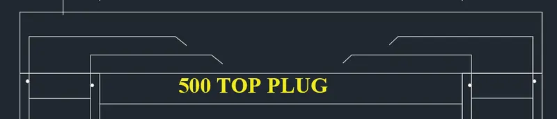
- Top Plug - The top plug is an unreinforced concrete plug, generally provided with a thickness of about 600 mm beneath the well cap to transmit the loads from the pier to the steining. Minimum grade of concrete used in top plug is M15.This is a plug at the top of the well below the well cap. This helps transferring the load through the granular material into the staining.
- Sand Filling - After concreting the bottom plug the sand is filled above the bottom plug and below top plug. Sand filling provide stability of well, reduce tensile stress produced by bending moment and distributes the load of super structure on to the bottom plug. Sand filling relieves load to steining to some extent.