Project 2
Using MATLAB/simulink and the drive cycle from the attached excel sheet, find-
- The max heat generation of the battery
- The SOC of the battery at 2 *104second of the battery operation
| Time | Time Step | Battery Current |
| 00:00.4 | 0.1 | -0.9632 |
| 00:00.5 | 0.2 | -0.952 |
| 00:00.6 | 0.3 | -0.9072 |
| 00:00.7 | 0.4 | -0.9632 |
| 00:00.8 | 0.5 | -1.0304 |
| 00:00.9 | 0.6 | -0.9632 |
| 00:01.0 | 0.7 | -1.0304 |
| 00:01.1 | 0.8 | -1.008 |
| 00:01.2 | 0.9 | -0.9856 |
| 00:01.3 | 1 | -0.9632 |
| 00:01.4 | 1.1 | -0.9184 |
| 00:01.5 | 1.2 | -0.9296 |
| 00:01.6 | 1.3 | -0.9296 |
| 00:01.7 | 1.4 | -0.9296 |
| 00:01.8 | 1.5 | -0.9184 |
| 00:01.9 | 1.6 | -0.9408 |
| 00:02.0 | 1.7 | -0.896 |
| 00:02.1 | 1.8 | -0.9072 |
| 00:02.2 | 1.9 | -0.9072 |
| 00:02.3 | 2 | -0.9408 |
| 00:02.4 | 2.1 | -0.9296 |
| 00:02.5 | 2.2 | -0.9296 |
| 00:02.6 | 2.3 | -0.9968 |
| 00:02.7 | 2.4 | -0.9968 |
| 00:02.8 | 2.5 | -0.9408 |
| 00:02.9 | 2.6 | -0.9408 |
| Battery resistance | 2 milli ohm |
Consider the battery resistance is 0.5 mOhm, delta time is 0.1 and entropic factor is 2
Aim : The max heat generation of the battery
heat generated = joules heat + entropy heat
Heat Generation:
Batteries generate heat during charge and discharge due to enthalpy changes, electrochemical polarization, and resistive heating inside the cell. Temperature variation inside the batteries can lead to the uneven temperature distribution which creates uneven charge/discharge behaviour within the battery pack. So, thermal runaway may occur in a cell when heat is not properly controlled and possibly cause fire and explosion.
entropy heat:
the heat generation due to entropy change inside a battery occurs when electro chemical reaction are performed. the entropy heat is reversible heat resulting from change in open circuit voltage with respect to temperature at two electrodes.
power
P=V*I=I^2*R
heat
H=∫P.dt with the limits of time 0 to t
H=I^2*R*t
where,
P=power
V=voltage
I=current
R=resistance
H=heat
T=time
The maximum current in the drive cycle is -0.896 at the time 2 minutes (120 seconds)
Therefore
Resistance = 0.5 milli ohm
Imax = -0.896 A
tmax = 120sec
Maximum joule heat generated=I^2*R*t
Maximum joule heat generated=(-0.896)^2*0.5*120
Maximum joule heat generated=0.8028*0.5*120
Maximum joule heat generated = 48.16 milli Joule
Entropic factor=2
Maximum heat generated= max joule heat + entropic heat
Maximum heat generated = 48.16+2
Maximum heat generated =50.16 milli joule
Maximum of heat generation of battery is 50.16 milli joule
b)
Aim : The SOC of the battery at 2 *104second of the battery operation
SOC = State of Charge is defines the how energy is usable for application
SOC = Q / Qmax
where,
Q = Available capacity
Qmax = Overall capacity
for the simulation model following blocks are used:
- Generic Battery - Implements a generic battery model for most popular battery types. Temperature and aging (due to cycling) effects can be specified for Lithium-Ion battery type.
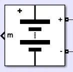
Nominal voltage (V)
The nominal voltage, Vnom, of the battery in V. The nominal voltage represents the end of the linear zone of the discharge characteristics. Default is
7.2.Rated capacity (Ah)
The rated capacity, Qrated, of the battery in Ah. The rated capacity is the minimum effective capacity of the battery. Default is
5.4.Initial state-of-charge (%)
The initial state-of-charge (SOC) of the battery. An SOC of 100% indicates a fully charged battery and 0% indicates an empty battery. This parameter is used as an initial condition for the simulation and does not affect the discharge curve (when the option Plot Discharge Characteristics is used). Default is
100.Battery response time (s)
The response time of the battery (at 95% of the final value). Default is
30. This value represents the voltage dynamics and can be observed when a current step is applied.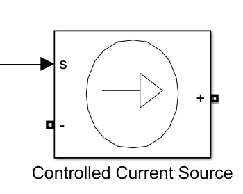
- Controlled current source - Converts the Simulink input signal into an equivalent current source. The generated current is driven by the input signal of the block.
You can initialize your circuit with a specific AC or DC current. If you want to start the simulation in steady-state, the block input must be connected to a signal starting as a sinusoidal or DC waveform corresponding to the initial values.
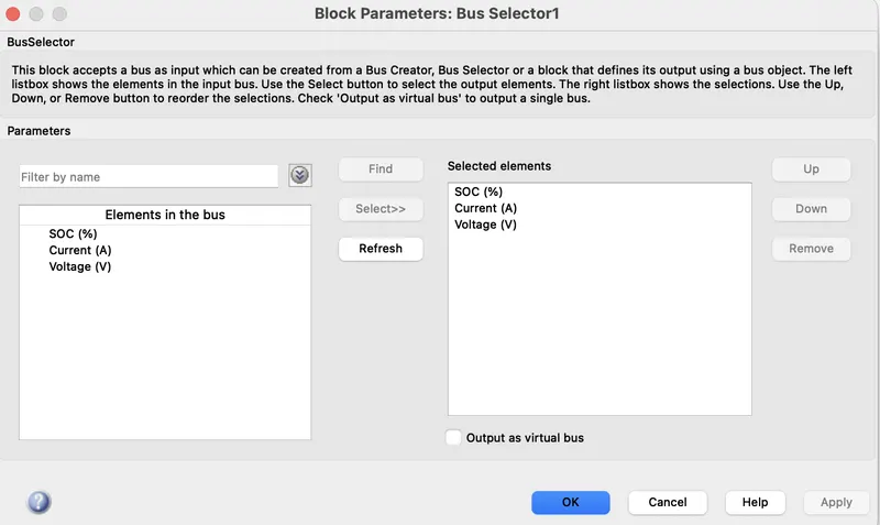
- Bus Selector -This block accepts a bus as input which can be created from a Bus Creator, Bus Selector or a block that defines its output using a bus object. The left listbox shows the elements in the input bus. Use the Select button to select the output elements. The right listbox shows the selections. Use the Up, Down, or Remove button to reorder the selections. Check 'Output as virtual bus' to output a single bus.
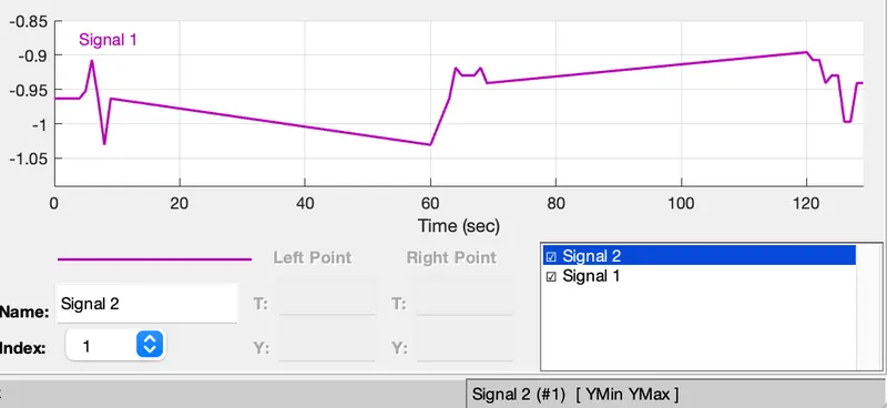
- Signal Builder Block -To use any type of signal till 208 stop time
- Scope- to Display the output graph
- Powergui -Set simulation type, simulation parameters, and preferences
simulation model:
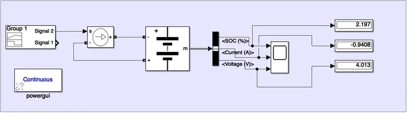
The current is negative becuase of the battery is charging condition
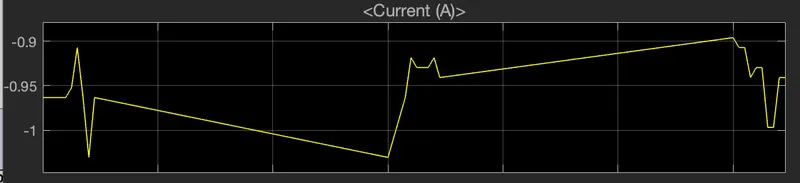
The soc,current & voltage of cell is shown below
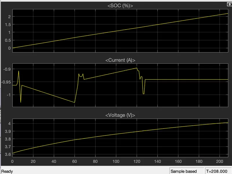
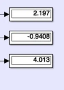
as from the above results The current is same as input the battery current withrespect to the time The current is negative becuase of the battery is charging condition and when see the voltage scope it raises the voltage from the 3.6v to 4.0 v as the battery is in the charging condition as we charge the battery the voltage also increases and when we move on to the soc block soc reperesents that the how much energy is used for the application available capacity /total capacity of the battery and in the charging condition the intinal state od charge wil be 0% as we need for the 208 seconds we get it as 2.197 it increases from 0%to 2.197%.
conclusion:
a: The Max heat generated in which the current flowing in and out i.e., charge and discharge due to internal resistance and chemical reaction during charging and discharging of the battery the heat is generates of Maximum of heat generation of battery is 50.16 milli joule.
b:The current is negative becuase of the battery is charging condition and when see the voltage scope it raises the voltage from the 3.6v to 4.0 v as the battery is in the charging condition as we charge the battery the voltage also increases and when we move on to the soc block soc reperesents that the how much energy is used for the application available capacity /total capacity of the battery and in the charging condition the intinal state od charge wil be 0% as we need for the 208 seconds we get it as 2.197 it increases from 0%to 2.197%.