Project 2
1)
ANS:-
AIM:- To develop the general arraangement for the RC office building and analyzing with design the building as per IS stadard code in TEKLA structural desginer.
PROCEDURE:-
step(1):-
- First open the TEKLA software in that open the new file.
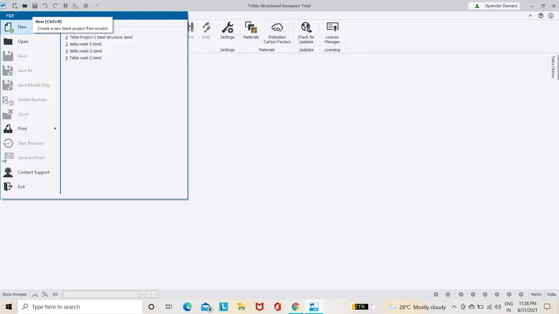
- Next go to model tab and select construction level.
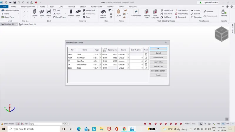
- Edit the construction level from base to roof .
- Click ok.
step(2):-
- Go to model tab.
- Select construction line unde the grid option.
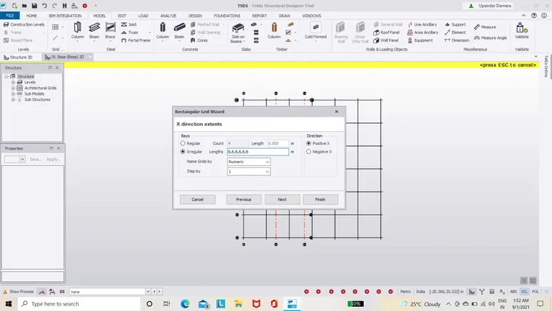
- Draw the grid as per the drawing provided in the question.
- Click ok.

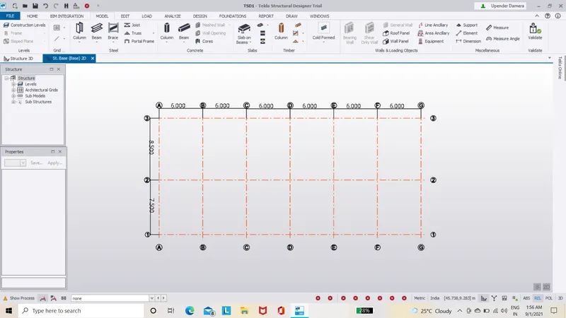
step(3):-
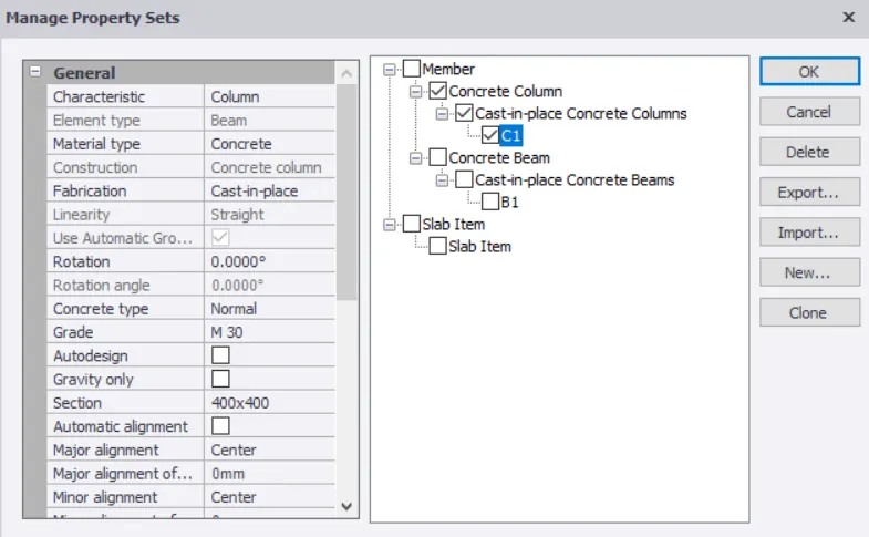
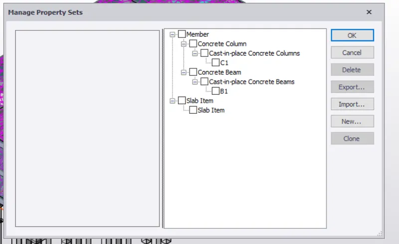
- Go to manage property set.
- Click new and add the concrete column.
- Edit the column size as 400x400 and grade as M55.
- Click ok.
step(4):-
- Go to model tab and select concrete column.
- Select C1 from property window.
- Place the column in all the grid point.
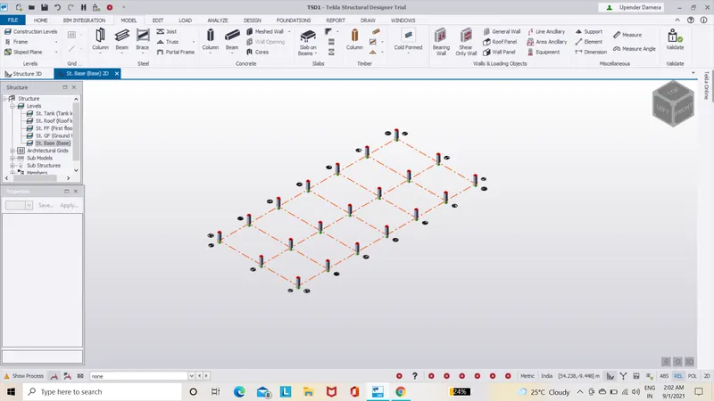
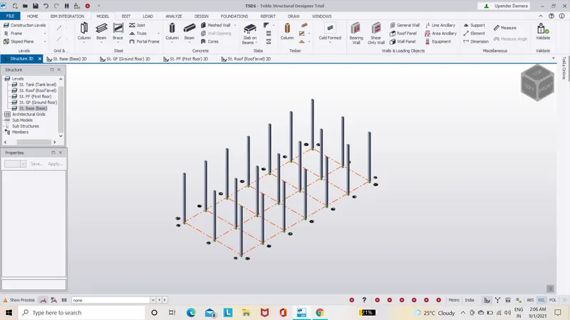
- Press ESC to exit the editing.
step(5):-
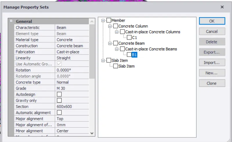
- Go to mange property set.
- Clcik new add the concrete column.
- Edit the beam size as 600x600 and grade as M55.
- Click ok.
step(6):-
- Go to model tab and select concrete beam.
- select B1 from property window.
- Place the beam in all the grid point.
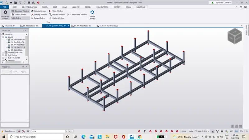
- Press ESC to exit the editing.
step(7):-
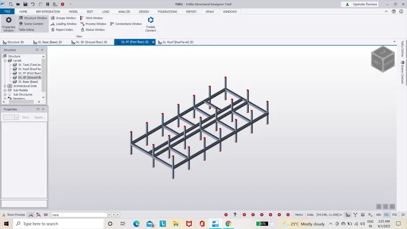
- Follow the same procedure in the first floor.
step(8):-
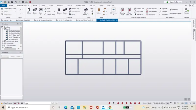
- Provide the beam in roof also.
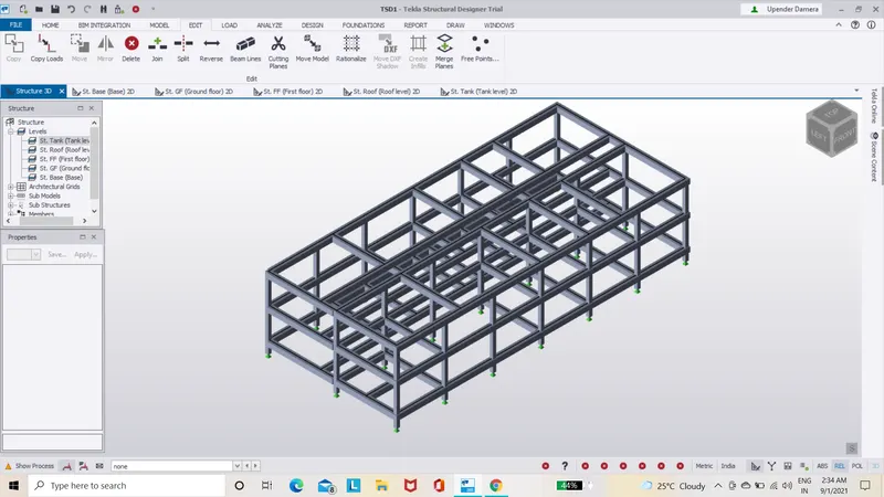
FULL 3D VIEW:-
step(9):-
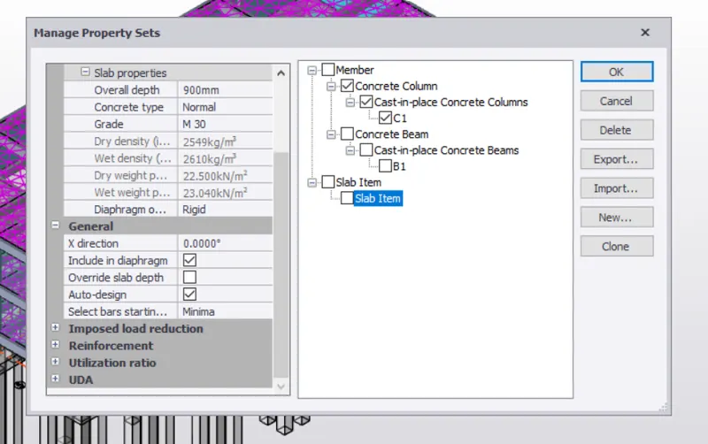
- Go to manage property set.
- click new and ad the cast insitu slab.
- Edit the slab as M55 and overall depth as 900mm.
- Click ok.
step(10):-
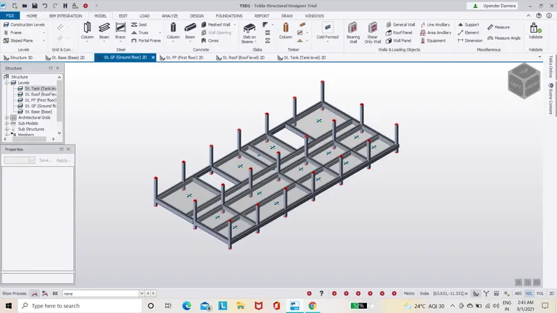
- Apply the slab properties in ground floor,first floor.
step(11):-
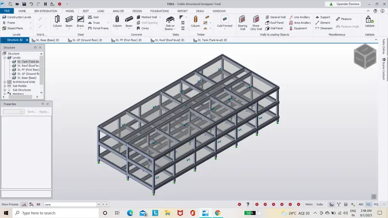
- Apply the slab propeerties in ground floor,first floor.
step(12):-
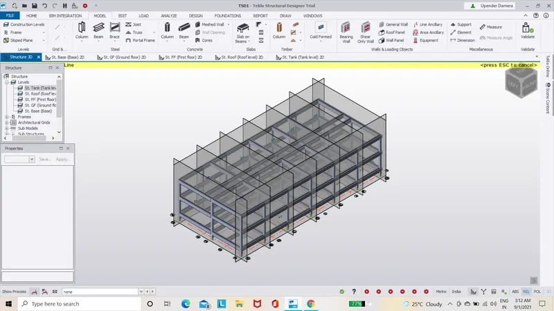
- Next go to frames and select the frames as shown below.
step(13):-
LOAD CALCULATIONS:-
Dead Load Calculations:-
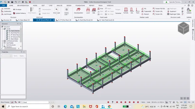
- Slab load =(model slab in software).
- Finishes loading(50mm thickness)=0.05x24KN/m2=1.2kn/m2.
- Brickwall with cement plaster thickness=230mm.
- unit weight =20KN/m3.(IS:875 part-1;Table-1).
- Floor height (Gorund floor to first floor)=3.6m.
- Brick wall loading=(230x20x3.7)/1000=10.5KN/m.
- Floor height (first floor to roof level)=3.65m.
- Brick wall loading=(230x20x3.65)/1000=11.2KN/m.
- Roof wall loading=1.5KN/m.
step(14):-
Applying load on Model:-
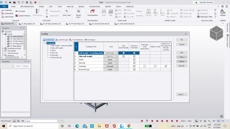
- Click the load tab in the ribbon panel.
- Select load cases and add the new loads such as wind,crane,seismic.
- Choose the type of the load as per load case titles.
- Click ok.
step(15):-
Generating Load combinations:-
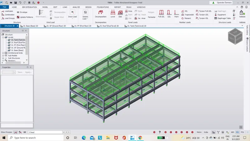
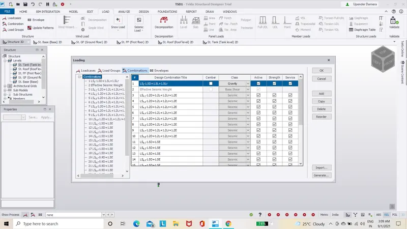
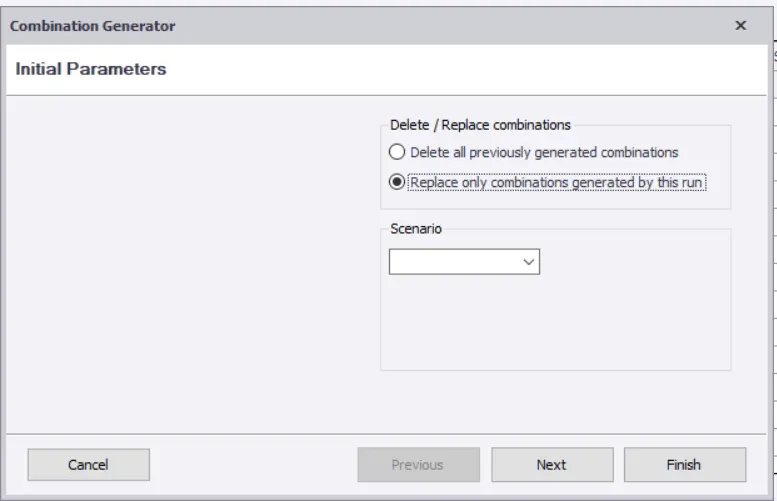
- To generate the load combinations from our entered load cases ,firsst need to select the load combintions from the load taqb in the ribbon panel.
- Click generate and process the load combinations.
- Then click finish once we got all the load combinations.
- click ok.
step(16):-
Applying dead load on grond floor:-
- Click the drop down list from the bottom tool bar.
- Choose dead load from the list.
- Select the area loading option from ther ribbon tab.
- Change the load value under the property panel to 1.2KN/m.
step(17):-
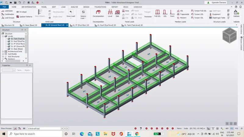
- Similarly apply the brickwall load in ground floor.
- Apply the brickwall load in first floor also.
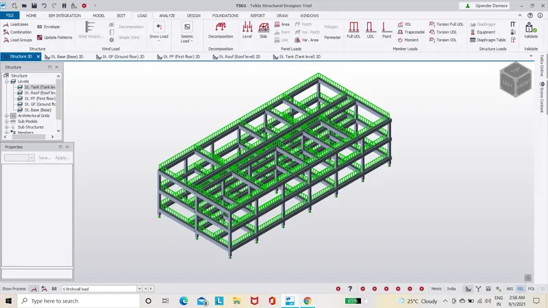
- Full 3D structure after appying the brick wall load.
step(18):-
Live Load calculations:-
As per IS 875 part-2,table-1.
Toilet=2kN.
staircase=5KN.
Store room=5KN.
Equipment room=10KN.
Conference room=5KN.
Canteen=3 KN.
Office room=3KN.
Water tank service load = 10KN.
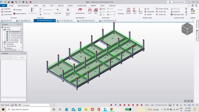
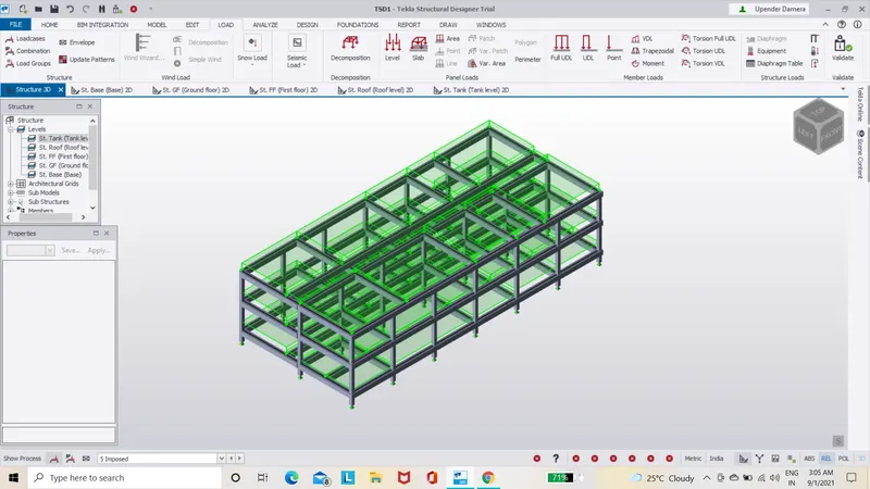
- Apply live load ground and first floor.
- Live load taken from IS 875 part-2,table-1.
- Change the load type as imposed and select area load.
- Then place the loading at suitable rooms.
step(19):-
Wind Load Calculations:-
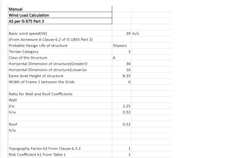
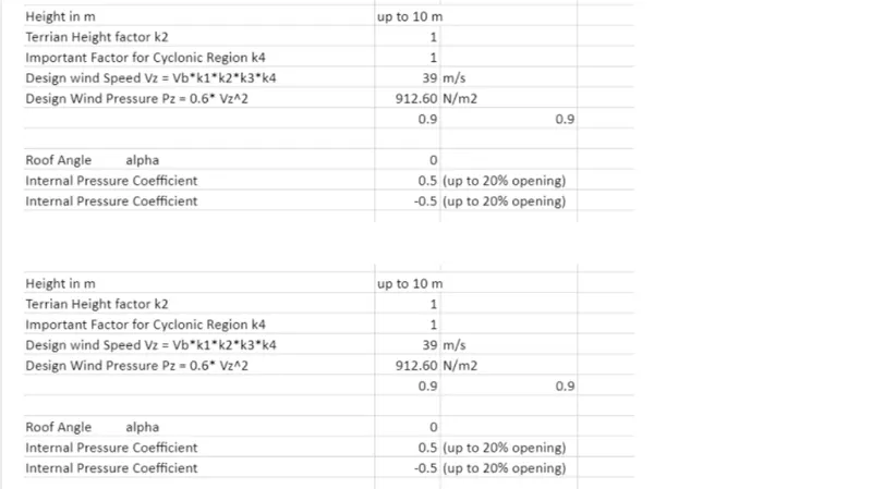
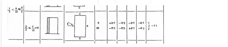
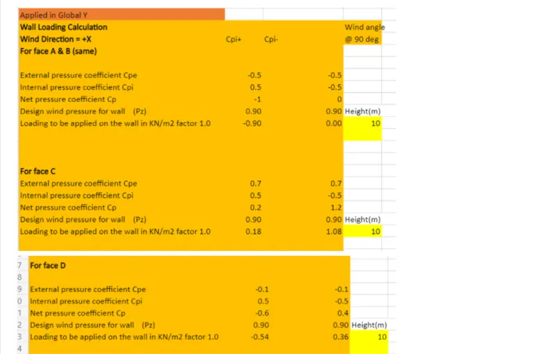
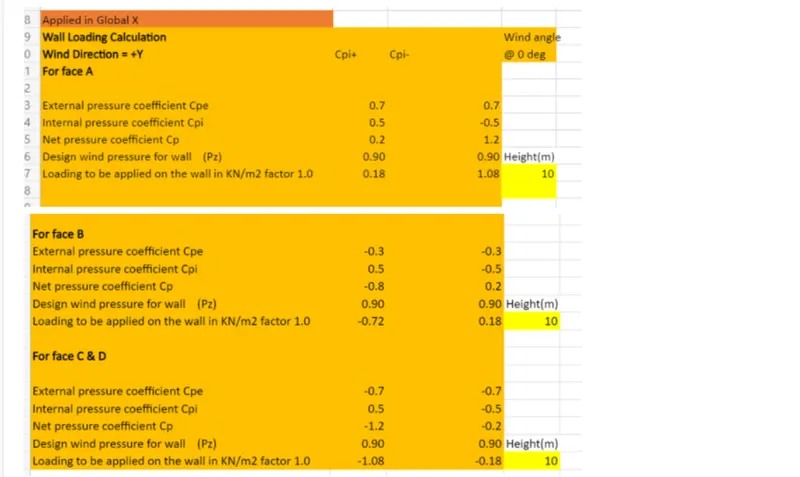
- Now place the values in the microsoft Excel worksheet and type the required content.
- Next we to apply the above calculated wind loads on different frmaes as shown below.
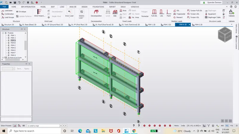
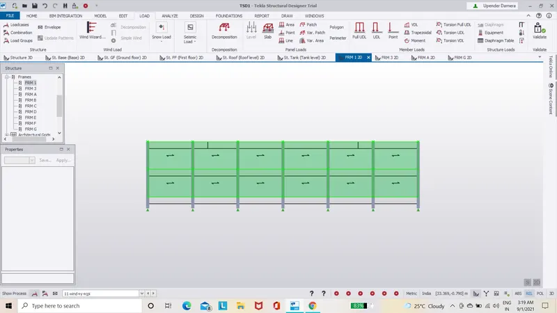
- Next go and select frame A and apply the wind load as shown below.
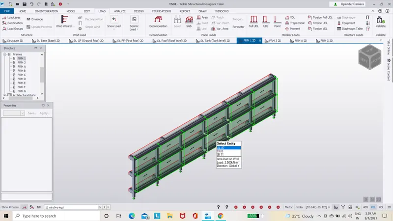
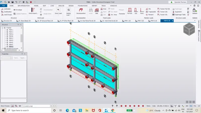
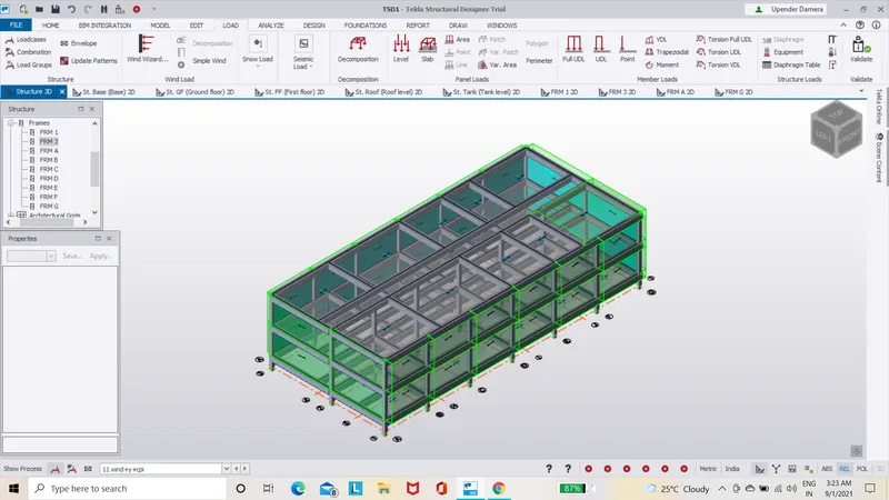
- The 3D sructure with wind applied as shown below.
step(20):-
Seismic Load Calculations:-
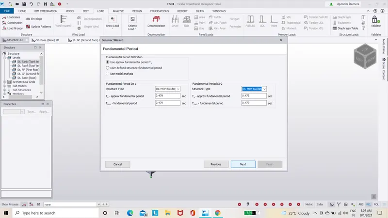
- Now under the load cases we need to select the seismic load and that will direct you to a new dialogue box.
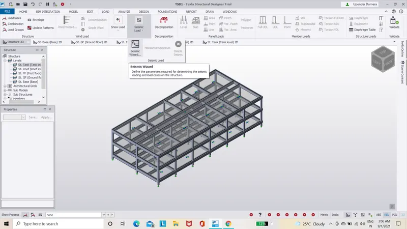
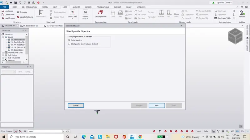
- Now in that dialogue box you will asked to select and check all the values,check weather the values of 1.00.
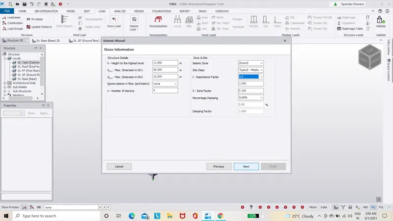
- NOw you will be directed to new dialogue box once you click next option.
- The dialogue boxes that appear in this process helps us to design the seismic load to the following structure.
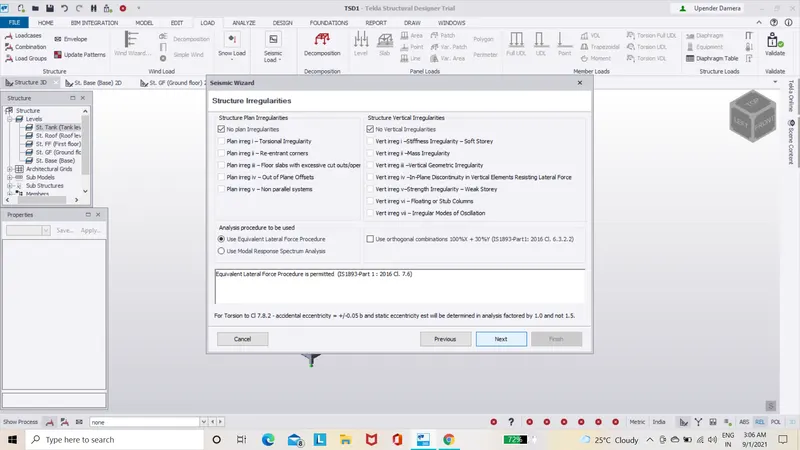
- Once all the parameters such as length,width,height and many more check is done click on finish.
- Noe if we open the down load bar w can find the seismic loads that have been applied to the structure.
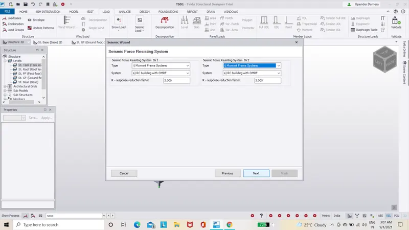
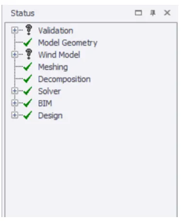
- Now that all the loads are applied we can now validate the structure to see and errors.
- If any errors are found they would be listed under the validate option and where we click on the error we will be directed to that error place and it is highlighted with a solid arrow.
- Correct the errors by changing the size of the particuler beam or column.
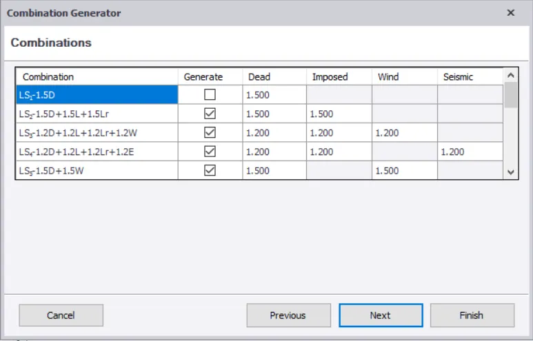
- we will be able to apply seismic load on the design members of the structure.
step(21):-
Analyze and design the building as per IS standrad code in TEKLA STRUCTURAL DESIGNER:-
- Now select the analyze option on the top task bar,under that we have to click the 1st order linear option.
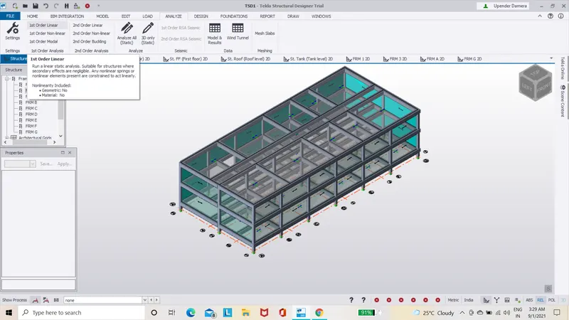
- Now the analysis is done and will show us the errors once it is done.
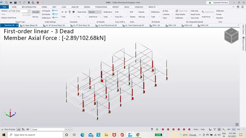
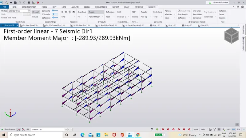
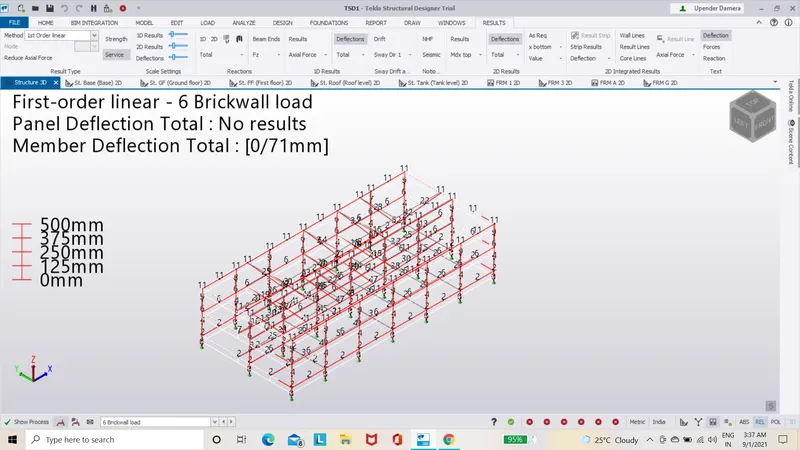
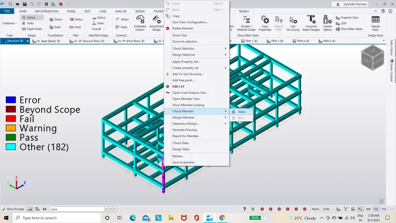
- Now click on the particular member and when we do the left click on it we get a dialogue box under that select the check member option and under that select the static option which displays another dialogue box.
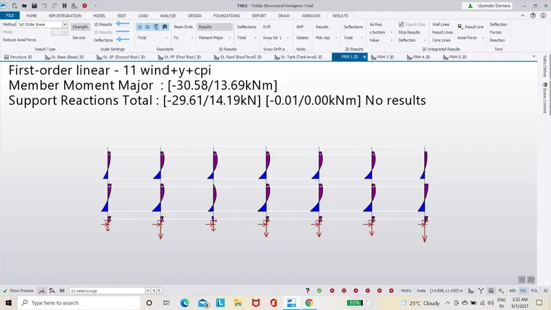
- Now in the new dialogue box we can find the load analysis manually done there we can check the value that is obtained of the loads that we have give or the material that we have choosen.
- Now check the values that we obtained by manual calculations and check the actual value that has to come out with the help of IS code book.
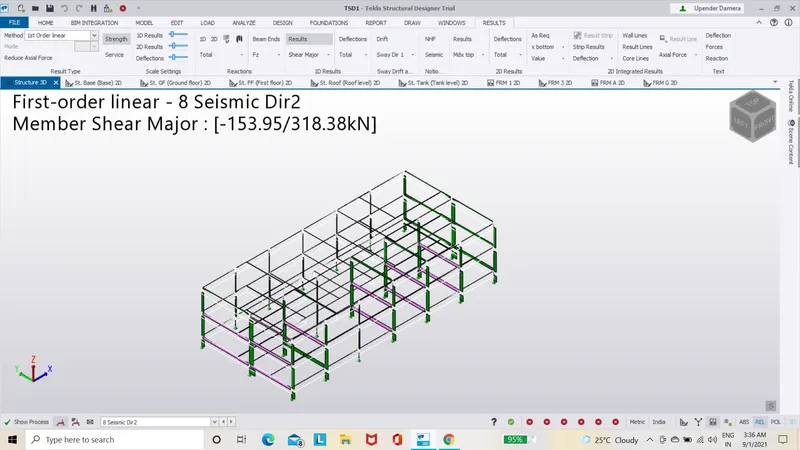
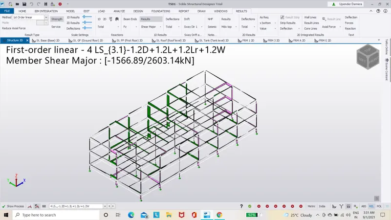
- Now change the size of the structural member accordingly.
- Now validate the structure for any errors.
step(22):-
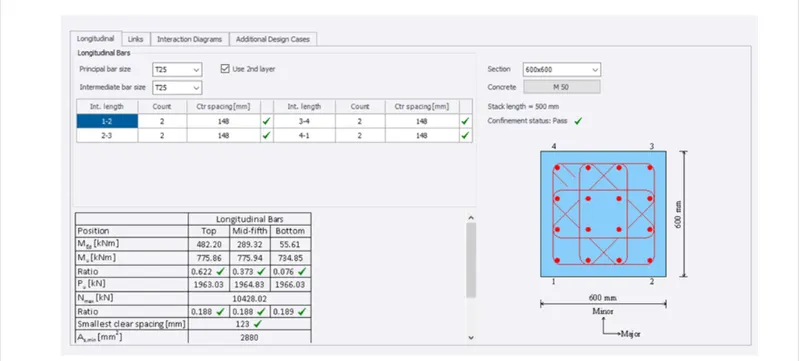
- Now taht analysis is done we can move on to designing of the members of the structure.
- Now select a column and give a right click then you can notice a dialogue box.
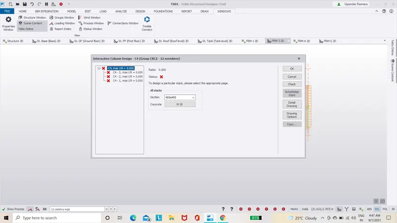
- Now in that dilogue box select the interactive design and under that select the static option.
- Now a new dialogue box appears about the properties of the column that you select.
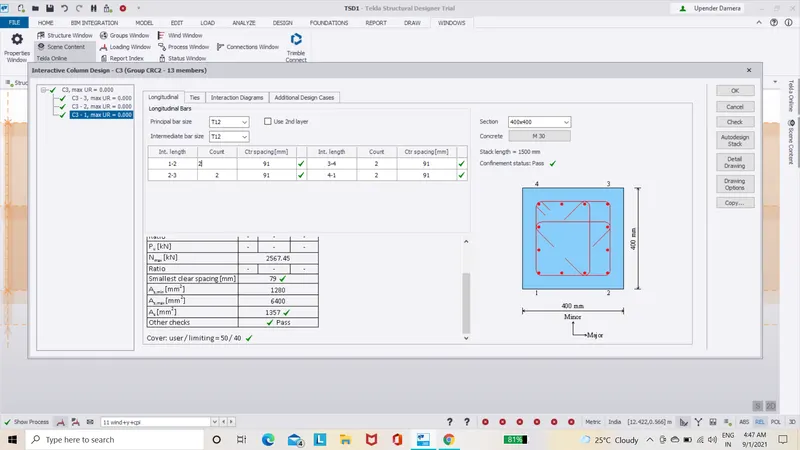
- Now check the status of the column and see weather it is red cross mark or green tick mark.
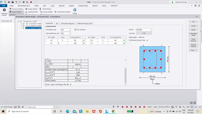
- If it is green tick mark it says that the column requirements for the structure are satisfied.
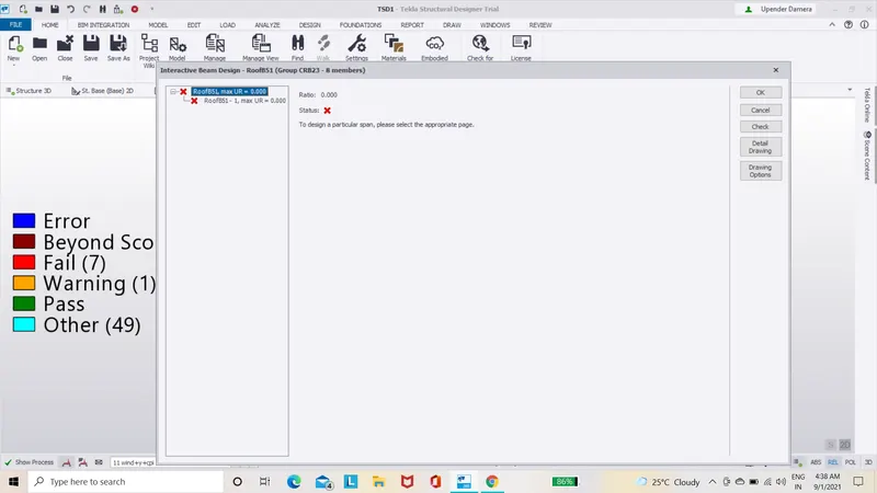
- If it is red cross mark change the propertiees either by increasing or decreasing the size of the column and this would surelychange the red cross mark with green tick mark.
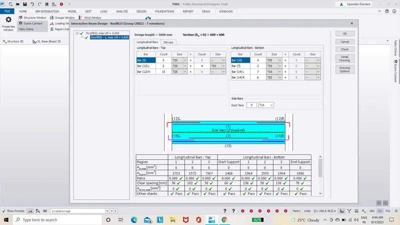
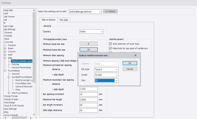
- Now select the design icon that is present on the top task bar of the Tekla software.
- Under taht select the settings option,under that select concrete and under that select the top longitudinal and bottom longitudinal values that are to be changed.
 `1
`1
- And now change as per requirements.
step(23):-
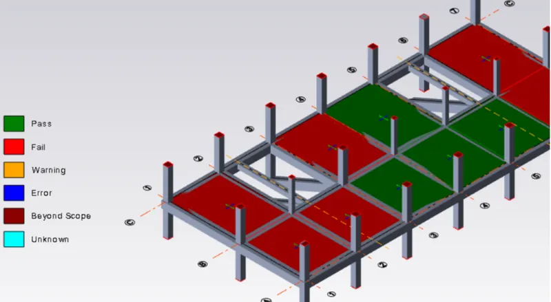
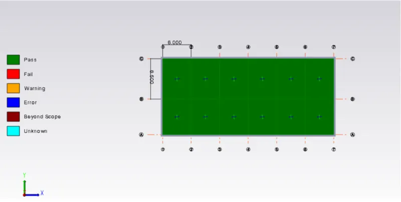
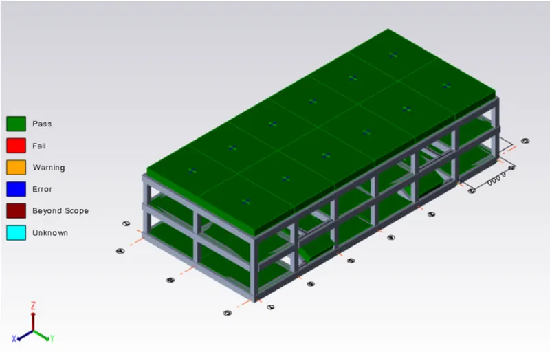
- After that we need to open the review view.
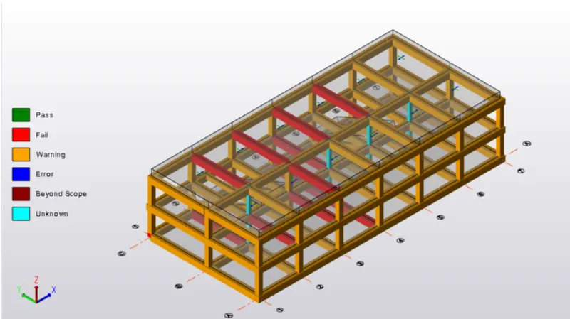
- By doing so we will be able to check the status of the structure.
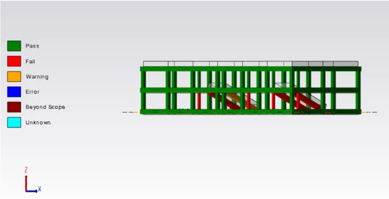
- Repeat the same process with the few RC beams and RC columns and slabs.
step(24):-
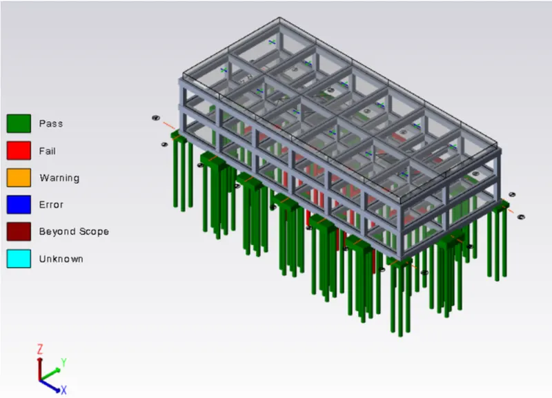
- Now for the foundations select the foundation icon.
- Now you need to select the catalogue option and add the desired foundation.
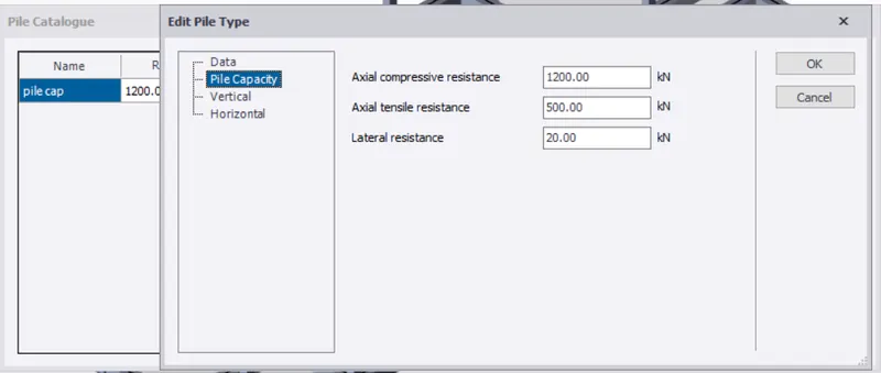
- Now you can select the pile cap column foundation option.
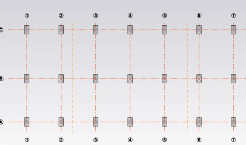
- Assign foundations for the structure.
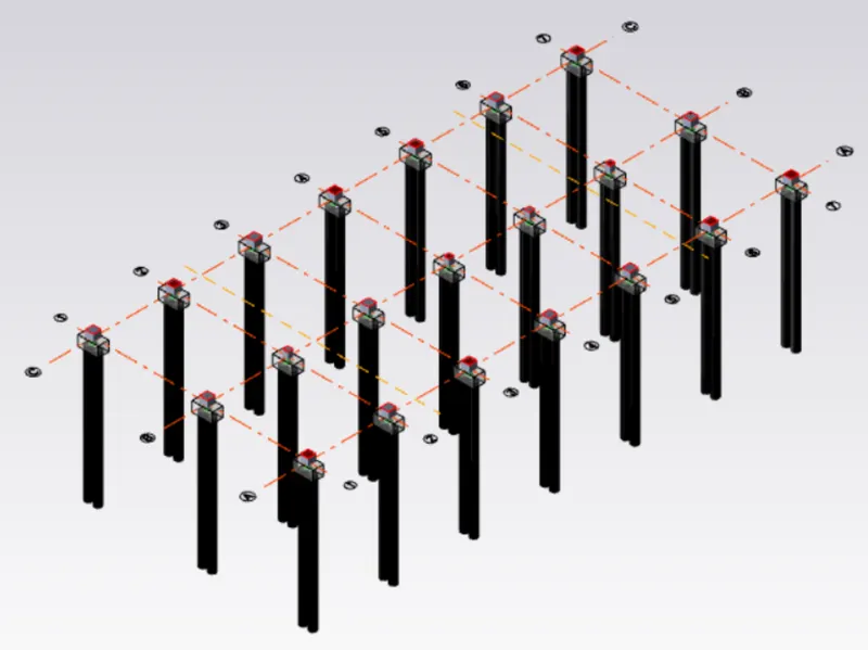
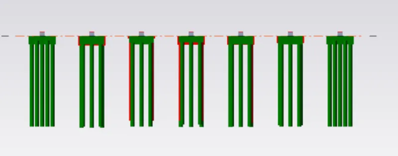
- Now design the foundation with the help of design pile cap option under he design isolated.
- Check for errors found.
- Go to the settings option under that select the foundation option and do the required changes.
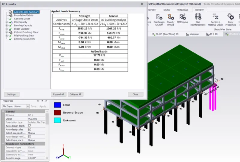
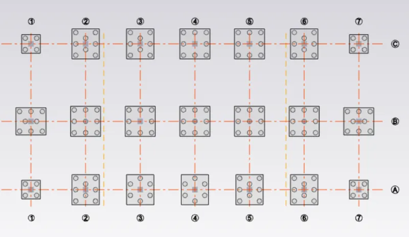
- Now you can see the structure is error free.
step(25):-
REPORTS:-
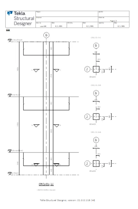
- Now to generate reports.

- Now under the reports tool bar we find the select option where we can choose the options.
- After selecting one among them click on the model report.
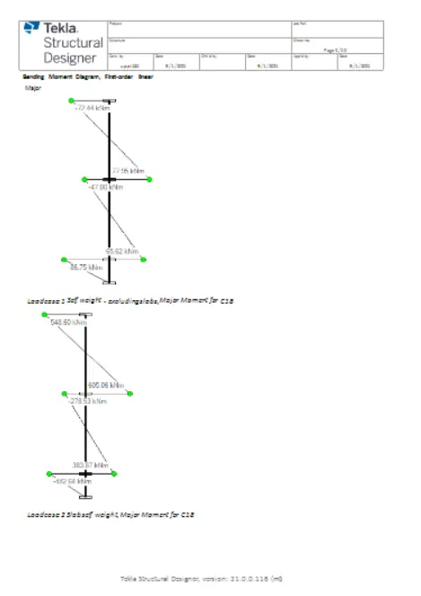
- Now you will be directed to a new dialogue box ,where you have to select few among them which are required for our structure input details.
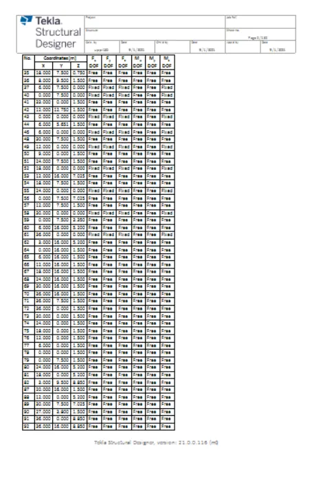
- After selecting few you can click on ok.
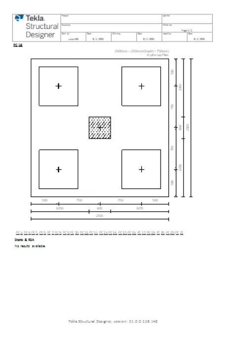
- Now select show reports option to see them.
- Now you can see reports are generated on your workspace.
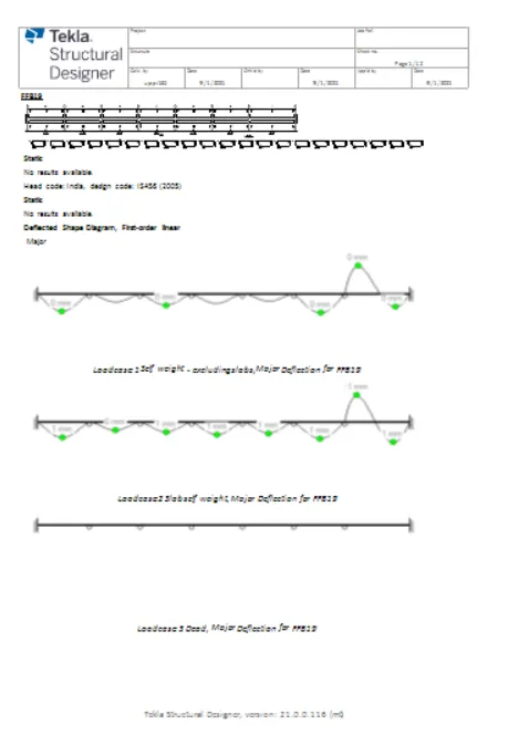
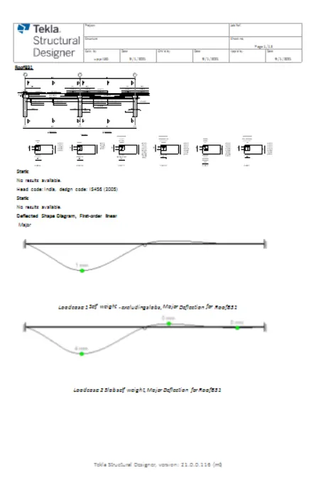
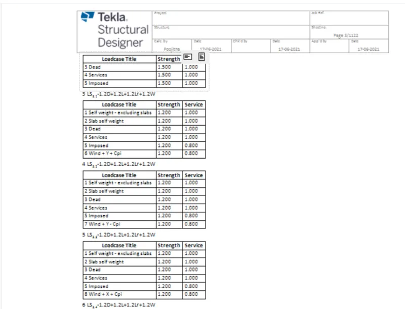
- You can click on the icon present on the tool bar for tha next page and previous page options.
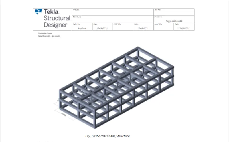
- Also you can click on the PDF option ton generate a PDF of the reports.

- Or you can convert the reports into any format such as PDF,EXCEL,WORD and many more of your choice depending on the availabilty.
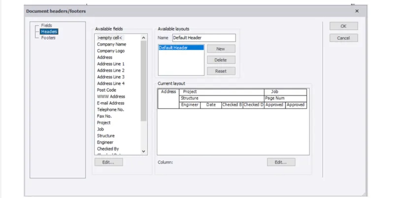
- Now with the help of edit header option you can edit the project name,address,checked by ,approved by and many more.
RESULIT:-
Hence by following above series of steps we will be able to develop general arrangement for the RC office buiding and analyze and design the building as per IS standard code in TEKLA STRUCTURAL DESIGNER. The building has been designed for dead ,live, wind and seiesmic loading.
Report are generated and extract drawings for structural plans,beam reinforcemnet details from the software.