Project
AIM:Carry out a system-level simulation of an all-terrain vehicle And Prepare a technical report explaining the model properties & comments on the results on Baja-All terrain vehicle(A.T.V.).
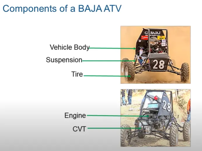
What is All terrain vehicle(A.T.V.) ???
All-Terrain Vehicles (ATVs) and Recreational Off-highway Vehicles (ROVs) are off-road-specific vehicles capable of handling all sorts of unpaved or rough terrain found in grasslands, mountain trails, sandy areas, etc. ATVs seat one rider and have a steering system with handlebars, etc., similar to a motorcycle, while ROVs are designed to fit two or more people and have a steering wheel system, etc., similar to an automobile. Both are used in a wide range of ways, from leisure and sport riding to utility work in the agriculture industry, etc.
STUDY
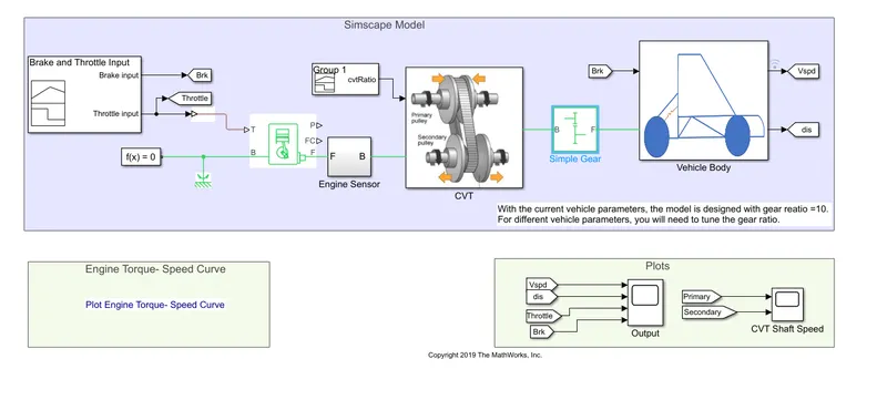
#CASE-1:Simulink model for Baja-ATV using CVT
Blocks used
1.CVT
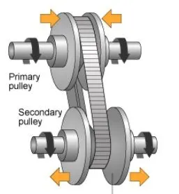
CVT known as continuously variable transmission
It allows the engine to operate at optimum power and efficiency in varying conditions. It does this by changing the gear ratio based on speed, rpm and load.
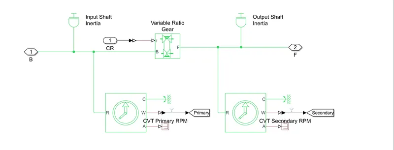
Now,Look inside the CVT block
sub-blocks of CVT
1.1 Variable Ratio Gear
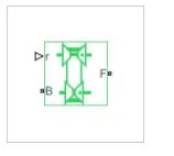
The Variable Ratio Transmission block represents a gearbox that dynamically transfers motion and torque between the two connected driveshaft axes, base and follower.
1.2 Ideal Rotational Motion Sensor

The Ideal Rotational Motion Sensor block represents an ideal mechanical rotational motion sensor, that is, a device that converts an across variable measured between two mechanical rotational nodes into a control signal proportional to angular velocity or angle. You can specify the initial angular position (offset) as a block parameter
#Now come outside the CVT block
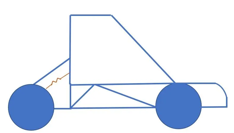
2.Vehicle body
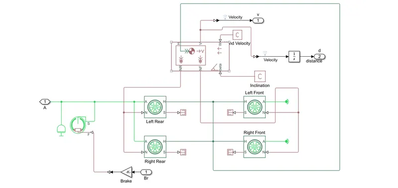
#Inside the vehicle Body
3.Solver Configuration block
the Solver Configuration block specifies the solver parameters that your model needs before you can begin simulation
4.Generic Engine
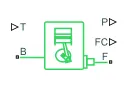
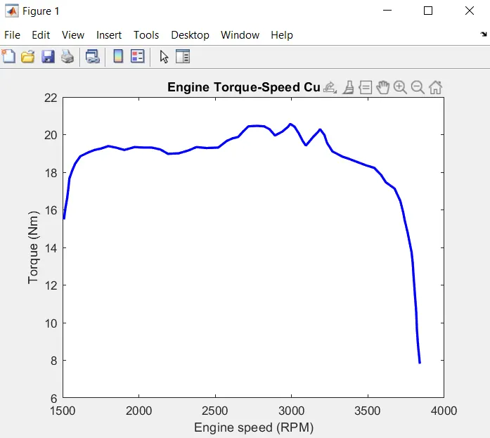
The Generic Engine block represents a general internal combustion engine. This block is a suitable generic engine for spark- ignition and diesel. Speed-power and speed-torque parameterizations are provided. A throttle physical signal input specifies the normalized engine torque. Optional dynamic parameters include crankshaft inertia and response time lag. A physical signal port outputs the engine fuel consumption rate based on the fuel consumption model that you choose. Optional speed and redline controllers prevent engine stall and enable cruise control.
#Blocks used for Input
5.Signal builder
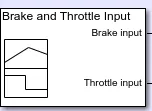
The Signal Editor block displays, creates, and edits interchangeable scenarios.
#Blocks used for Output
6.Scope

Display signals generated during simulation.
#Inputs
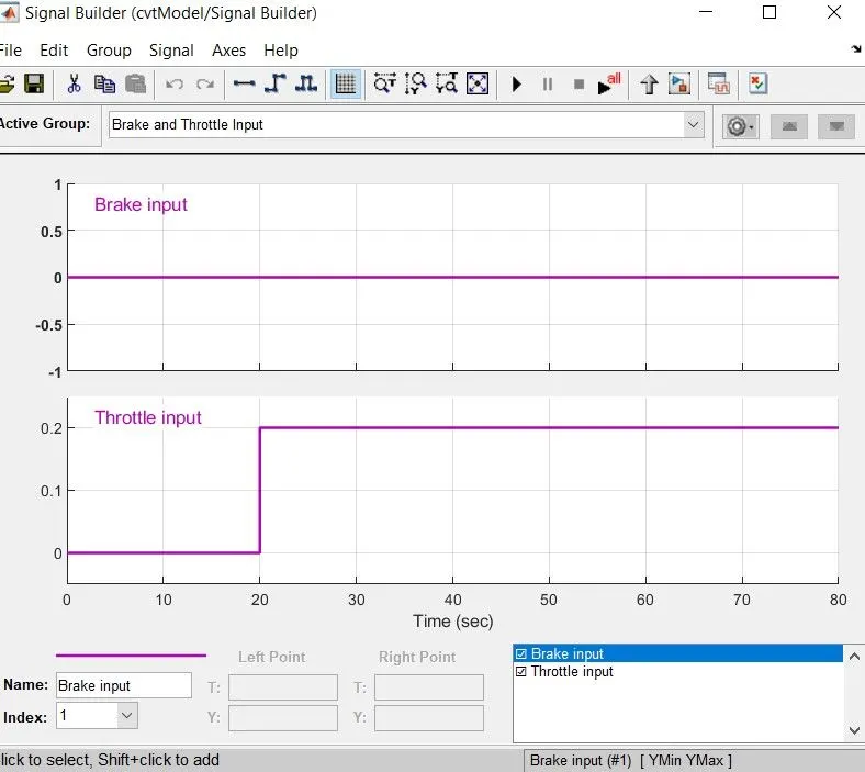
Input value of brake and throttle
The brake is constant at 0 and throttle input is 0 at start and then maximum 0.2 and stays constant.
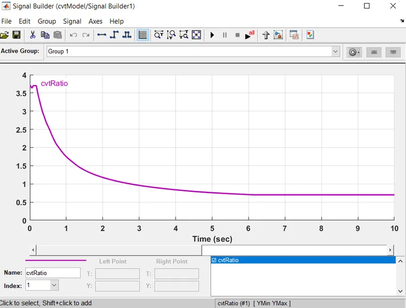
Input value of CVT ratio
#Outputs
To View the Output
First run the Simulation
then Double-click on the scopes
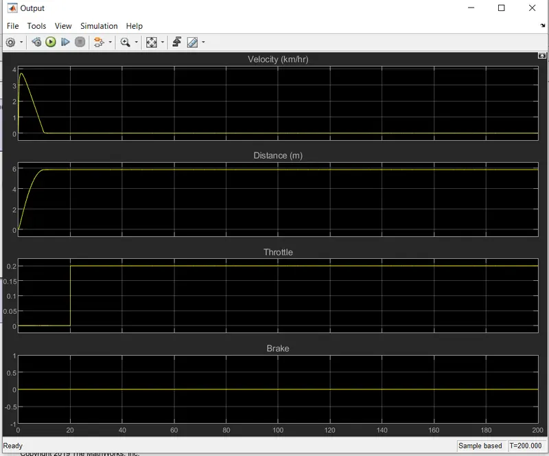
Output for Vehicle Speed
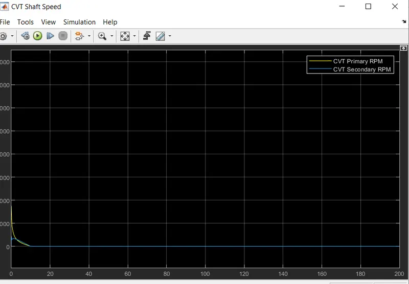
Output of CVT Shaft
#Case-2:Simulink model for Baja-ATV using CVT with Dashboard
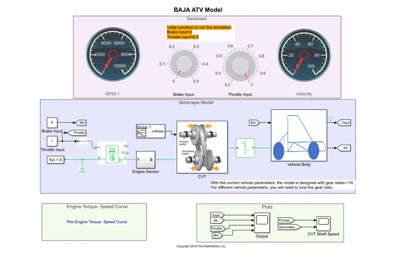
In this case we have used the cirscular gauge and knob
and we can change the value through knob directly also
#Blocks used different from case-1
1.The Circular Gauge
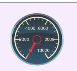
The Circular Gauge block displays the instantaneous value of the connected signal throughout simulation. You can modify the range and tick values on the Circular Gauge block to fit your data. Use the Circular Gauge block with other dashboard blocks to build an interactive dashboard of controls and indicators for your model.
2.Knob
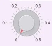
The Knob block tunes the value of the connected block parameter to during simulation
#Inputs
3.Signal builder
The Signal Editor block displays, creates, and edits interchangeable scenarios.
4.Constant

The Constant block generates a real or complex constant value signal.
#Blocks used for Output
5.Scope
Display signals generated during simulation.
#Inputs
#using constant block
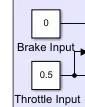
Brake input=0
Throttle input=0.5
#signal builder
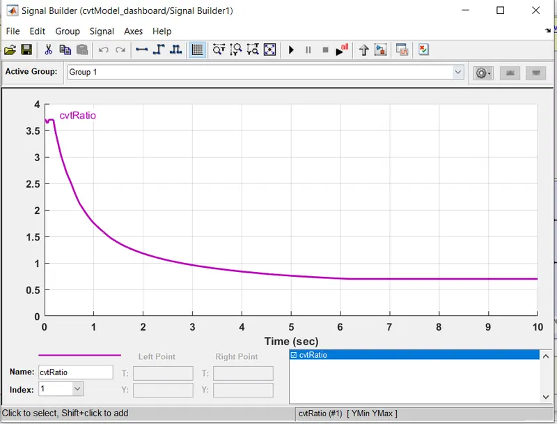
Input value of CVT ratio
#Output
To View the Output
First run the Simulation
then Double-click on the scopes
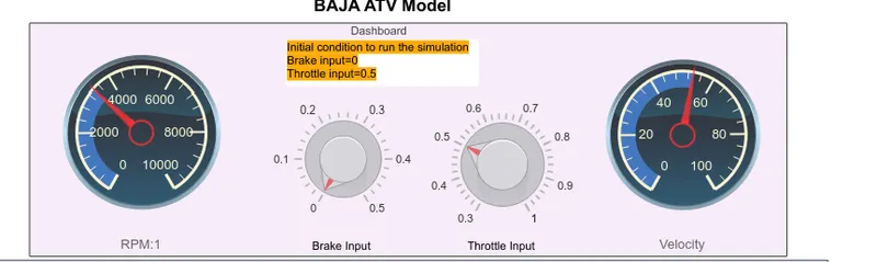
Output shown in circular gauge and Knob.
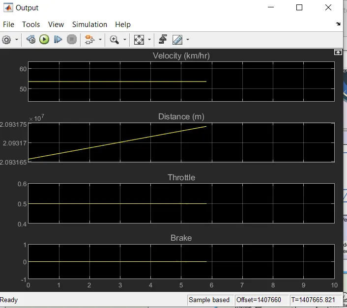
Vehicle Speed
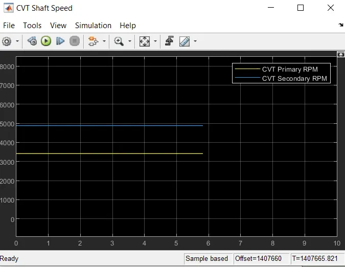
CVT Shaft Speed
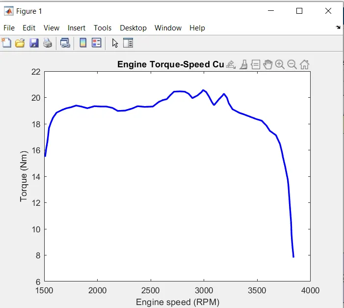
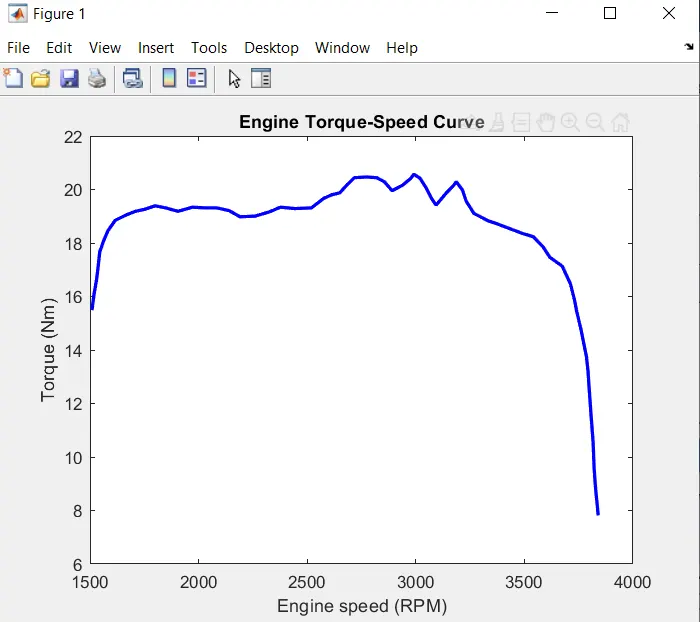
#Case-3:Simulink model for Baja-ATV using CVT with Lookup-Table
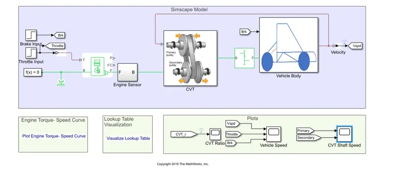
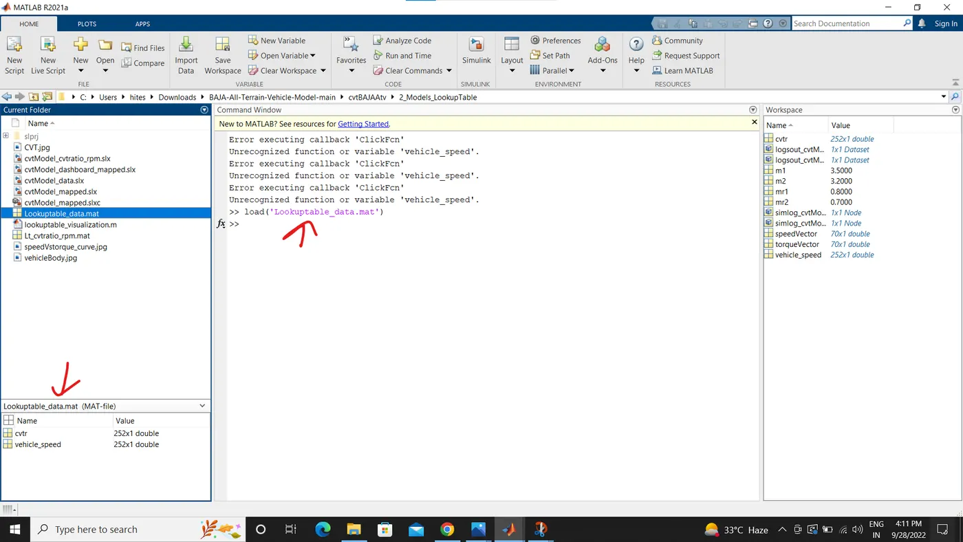
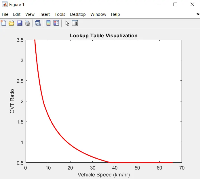
when you will open this ,you will get the Look up table error and
you can solve it by running the Lookuptable_data.mat file in Matlab Script and it will work as variable Input for Look up Table.
The Lookup-table is inside the CVT block
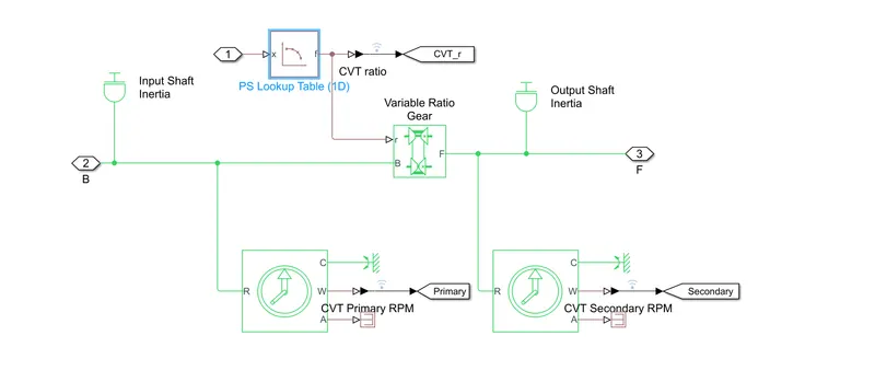
The Look-up table
This block represents a physical signal converter whose input-output relationship is specified by a lookup table. The table grid must be in strictly ascending or strictly descending order, but the spacing can be nonuniform.
#Blocks used different from case-1 and 2
1.The Look-up table
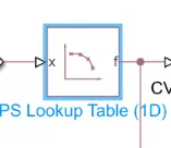
This block represents a physical signal converter whose input-output relationship is specified by a lookup table. The table grid must be in strictly ascending or strictly descending order, but the spacing can be nonuniform.
2.Step

The Step block provides a step between two definable levels at a specified time. If the simulation time is less than the Step time parameter value, the block's output is the Initial value parameter value. For simulation time greater than or equal to the Step time, the output is the Final value parameter value.
#Inputs
3.Step block
4.Matlab script
Variable Input Used for Look-up table
#Blocks used for Output
5.Scope
Display signals generated during simulation.
#Outputs
To View the Output
First run the Simulation
then Double-click on the scopes
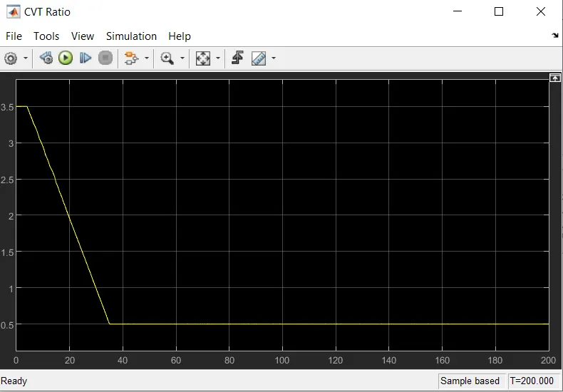
Output of CVT Ratio
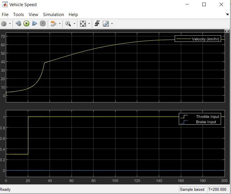
Output of Vehicle Speed
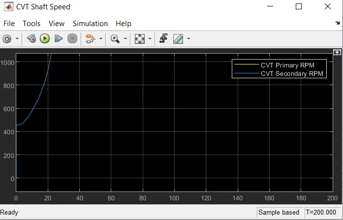
Output of CVT speed
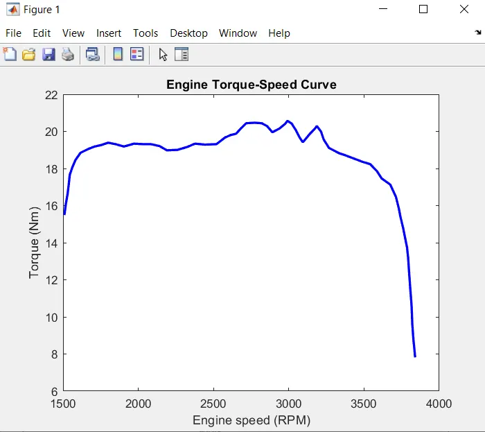
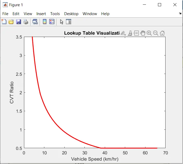
#Case-4:Simulink model for Baja-ATV using CVT with Lookup-Table and Dashboard
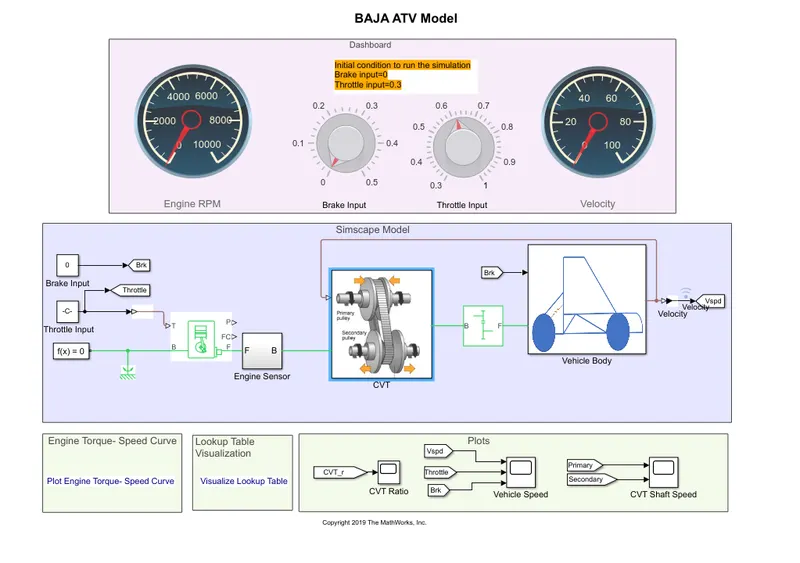
when you will open this ,you will get the Look up table error and
you can solve it by running the Lookuptable_data.mat file in Matlab Script and it will work as variable Input for Look up Table.
The Lookup-table is inside the CVT block
The Look-up table
This block represents a physical signal converter whose input-output relationship is specified by a lookup table. The table grid must be in strictly ascending or strictly descending order, but the spacing can be nonuniform.
#Blocks Used
1.The Circular Gauge
The Circular Gauge block displays the instantaneous value of the connected signal throughout simulation. You can modify the range and tick values on the Circular Gauge block to fit your data. Use the Circular Gauge block with other dashboard blocks to build an interactive dashboard of controls and indicators for your model.
2.Knob
The Knob block tunes the value of the connected block parameter to during simulation
1.Constant
The Constant block generates a real or complex constant value signal.
2.Matlab script
Variable Input For Look up Table
#Blocks used for Output
5.Scope
Display signals generated during simulation.
Outputs
To View the Output
First run the Simulation
then Double-click on the scopes
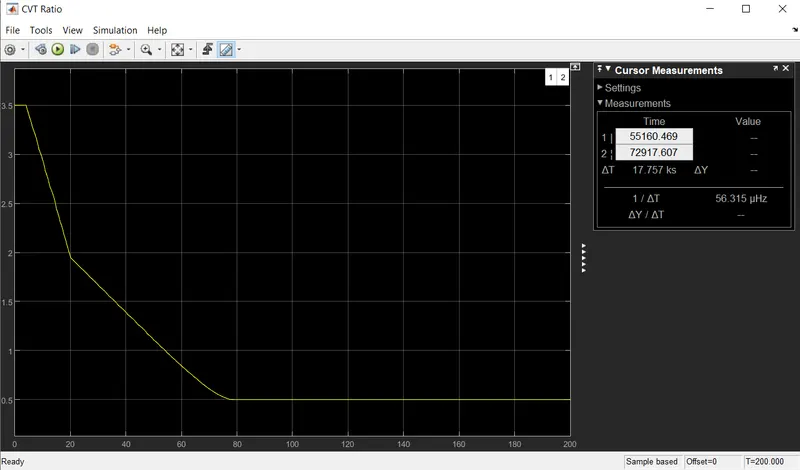
Output of CVT Ratio
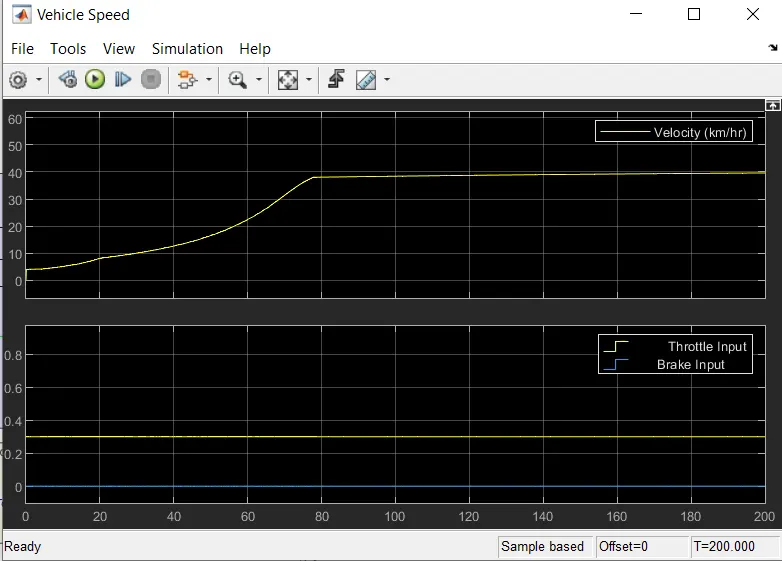
Output of Vehicle Speed
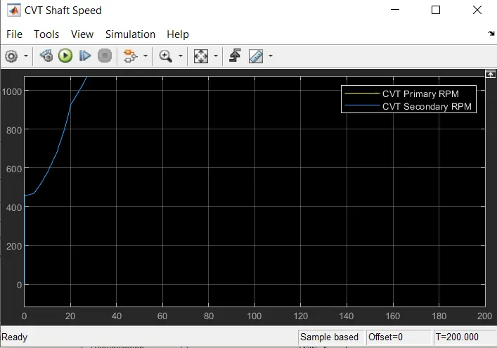
Output of CVT shaft speed
CONCLUSION
we have done the four different case study for the BAJA ATV WITH CVT.