Project
Analysis of BAJA All Terrain Vehicle
Aim:
To simulate the model of All Terrain Vehicle and to analyse the properties and parameters of the model.
Overview:
An all-terrain vehicle (ATV), also known as a light utility vehicle (LUV), a quad bike, or simply a quad. It is a vehicle that travels on low-pressure tires, with a seat that is straddled by the operator, along with handlebars for steering control. As the name implies, it is designed to handle a wider variety of terrain than most other vehicles. By the current ANSI definition, ATVs are intended for use by a single operator, although some companies have developed ATVs intended for use by the operator and one passenger. These ATVs are referred to as tandem ATVs.
Blocks:
CVT: A continuously variable transmission (CVT) is an automatic transmission that can change seamlessly through a continuous range of gear ratios. This contrasts with other transmissions that provide a limited number of gear ratios in fixed steps. The flexibility of a CVT with suitable control may allow the engine to operate at a constant RPM while the vehicle moves at varying speeds.
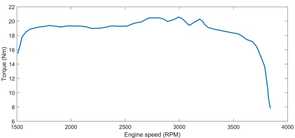
Generic Engine: The Generic Engine block represents a general internal combustion engine. Engine types include spark-ignition and diesel. Speed-power and speed-torque parameterizations are provided. A throttle physical signal input specifies the normalized engine torque. Optional dynamic parameters include crankshaft inertia and response time lag. A physical signal port outputs engine fuel consumption rate based on choice of fuel consumption model. Connections F and B are mechanical conserving ports associated with engine crankshaft and engine block. Ports P and FC are physical signal ports. The speed and torque vector values are obtained from the graph and can be viewed form the Matlab workspace.
As observed from the graph, the torque value is high and it increases until the engine attains its maximum speed and then starts to fall. In this model, the max. engine speed is 3840 rpm.
signal builder (brake and throttle input):
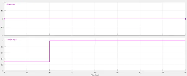
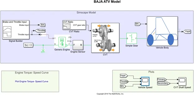
The signal builder shows the brake and throttle input. Brake input is 0 throughout 80 seconds whereas for throttle input, it is 0.3 for 20 seconds and reaches the maximum 1 throughout rest 80 seconds.
Signal builder (CVT ratio):
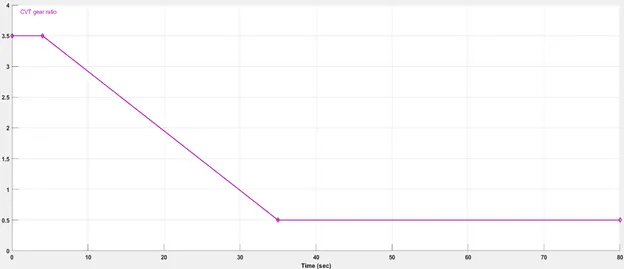
For 0.5 seconds, gear ration is 3.5. Then gradually decreases to 0.5 at 30.5 seconds and it will be constant till 80 seconds.
Engine sensor:
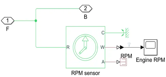
The Ideal Rotational Motion Sensor (RPM sensor) block represents an ideal mechanical rotational motion sensor, that is, a device that converts an across variable measured between two mechanical rotational nodes into a control signal proportional to angular velocity or angle. Connections R and C are mechanical rotational conserving ports that connect the block to the nodes whose motion is being monitored. Connections W and A are physical signal output ports for velocity and angular displacement, respectively. The block positive direction is from port R to port C.
Simple gear: The Simple Gear block represents a gearbox that constrains the connected driveline axes of the base gear, B, and the follower gear, F, to corotate with a fixed ratio that you specify. You choose whether the follower axis rotates in the same or opposite direction as the base axis. If they rotate in the same direction, the angular velocity of the follower, ωF, and the angular velocity of the base, ωB, have the same sign. If they rotate in opposite directions, ωF and ωB have opposite signs. The NF/NB ratio is given as 12 and the o/p shaft rotates in the same direction as i/p shaft.
CVT Subsystem:
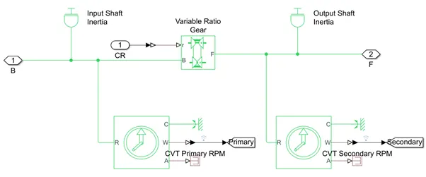
- Inertia: By default, the block has one mechanical translational conserving port. The block positive direction is from its port to the reference point. This means that the inertia torque is positive if inertia is accelerated in positive direction.
- Variable Ratio Transmission block: This represents a gearbox that dynamically transfers motion and torque between the two connected driveshaft axes, base and follower. Ignoring the dynamics of transmission compliance, the driveshafts are constrained to corotate with a variable gear ratio that you control. You can choose whether the follower axis rotates in the same or opposite direction as the base axis. If they rotate in the same direction, ωF and ωB have the same sign. If they rotate in opposite directions, ωF and ωB have opposite signs.
Vehicle body subsystem:

1.Double shoe brake: The Double-Shoe Brake block represents a frictional brake with two pivoted rigid shoes that press against a rotating drum to produce a braking action. The rigid shoes sit inside or outside the rotating drum in a diametrically opposed configuration. A positive actuating force causes the rigid shoes to press against the rotating drum. Viscous and contact friction between the drum and the rigid shoe surfaces cause the rotating drum to decelerate. The following specifications are fed to the brake.
2.Vehicle body: The Vehicle Body block represents a two-axle vehicle body in longitudinal motion. The vehicle can have the same or a different number of wheels on each axle. For example, two wheels on the front axle and one wheel on the rear axle. The vehicle wheels are assumed identical in size. The vehicle can also have a center of gravity (CG) that is at or below the plane of travel.
3.Tire: The Tire (Magic Formula) block models a tire with longitudinal behaviour given by the Magic Formula. The block can model tire dynamics under constant or variable pavement conditions. The longitudinal direction of the tire is the same as its direction of motion as it rolls on pavement. This block is a structural component based on the Tire-Road Interaction (Magic Formula) block. The parameters for the tire are being fed and this applies for all the other 3 tires.
Simulink Model(Without LookUp Table):
Without Dashboard
Model Explanation:
The agenda of this model is to analyse the vehicle behaviour with respect to the throttle and brake. The throttle and brake is given as the input to the generic engine. The speed an dtroque values are defined in the script file. Generic block output is given to engine sensor. Engine sensor output and CVT ratio output is fed to CVT. In CVT, the input at primary shaft is given to variable gear ratio. This output is measured at the Output shaft. Output of CVT is transferred to vehicle body sub system. When the throttle value is maximum,high velocity is obtained in ATV. In this model no brakes are applied.
RESULT:
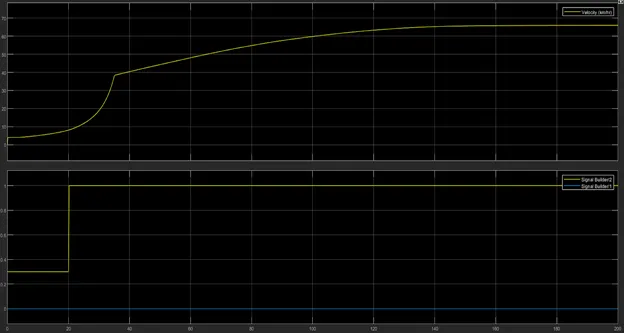
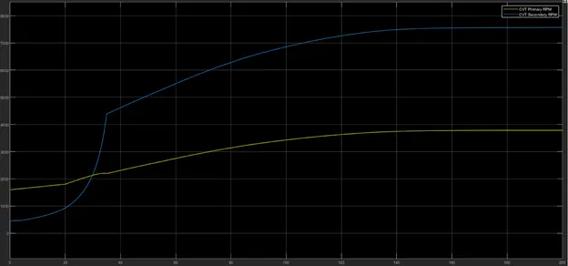
Graph shows that the velocity is 0.4 when the throttle input is 0.3. The velocity increases for 20 secs and at 20 secs the velocity value is 0.9. Now at 20 secs, the throttle input is given fully and the velocity value increases and reaches a maximum value and continues to remain constant thereafter.
With Dashboard:
A Simulink model of the BAJA ATV model with dashboard is shown below. All the other systems are the same as the previous Simulink model.
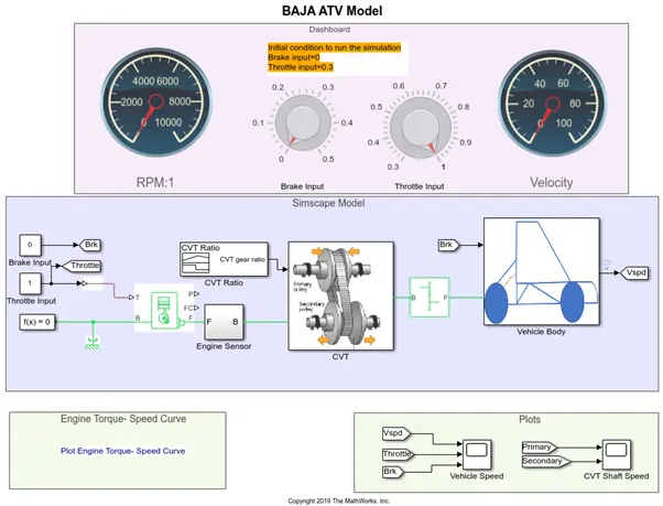
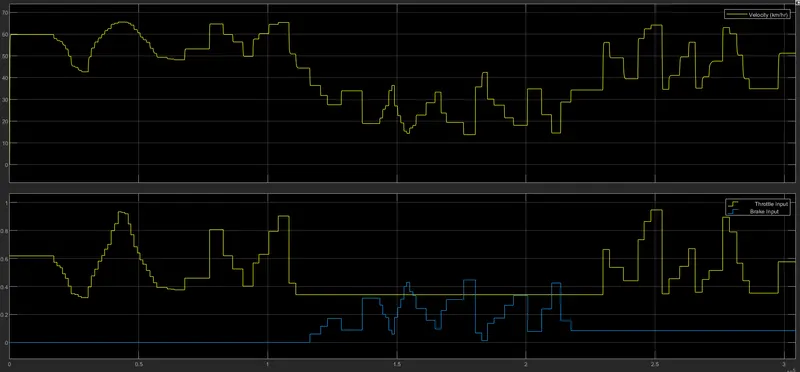
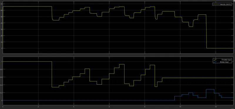
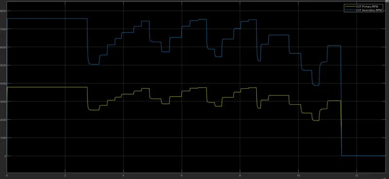
The only difference here compared with the previous model is that, in this case a variable brake and throttle input is given. The input is varied using a knob. The output for the varied throttle and speed is viewed from the rpm and velocity gauge. The initial conditions of the brake is 0 and throttle is 0.3
Result:
Simulink Model(With LookUp Table)
Without Dashboard:
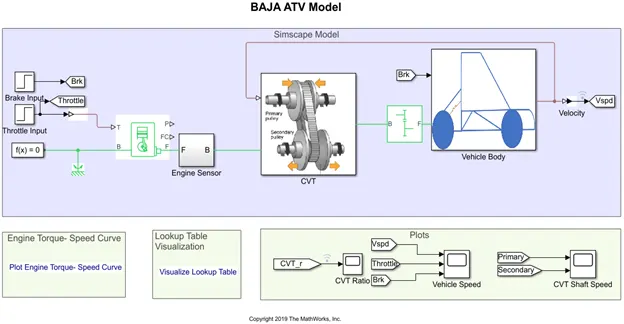
In this model, the signal builder inputs are replaced as two step blocks one for each input. Also the CVT ratio signal builder block is removed. Instead the output velocity is fed back to the CVT block. The CVT block adjusts the CVT ratio in accordance with the lookup table. All the other systems are the same as discussed in the above two methods.
Result:
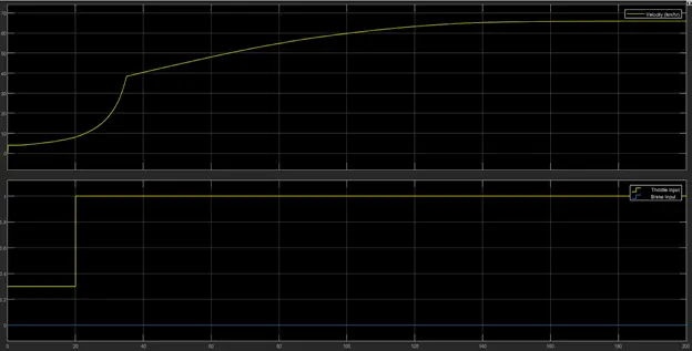
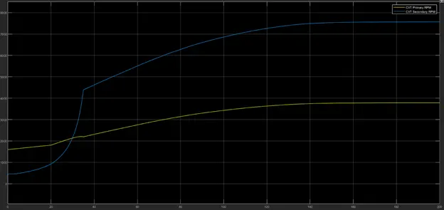
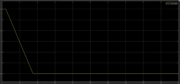
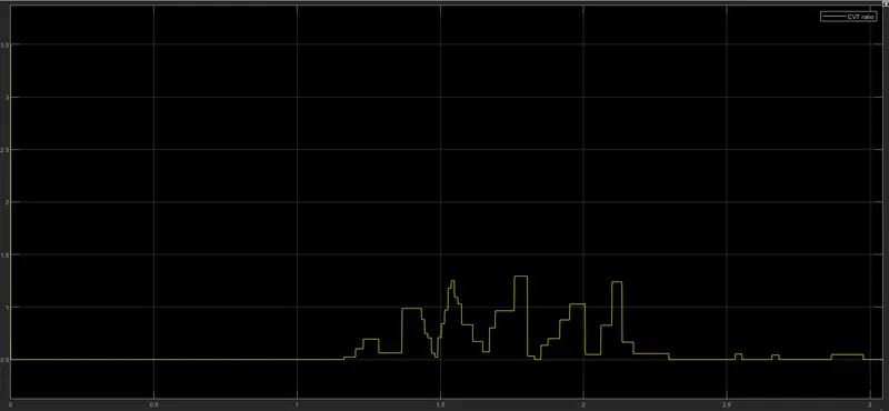
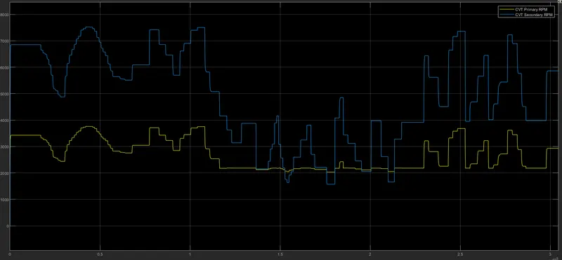
From the above plot it is clear the CVT ratio changes according to the feedback it receives form the output. Initially when the throttle is given as 0.3, the velocity is 0.4. It remains the same for 20 secs . At 20 secs, the throttle is increased to 1 and the velocity gradually increases and attains a maximum value after which it remains constant. When the velocity increases, the CVT ratio drops down gradually and it reaches the lowest value and remains constant for the entire time. According to the variation in CVT ratio, the primary and secondary speed also changes.
With Dashboard:
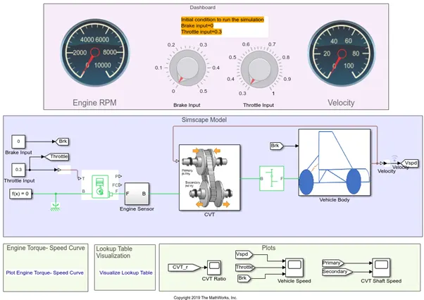
The only difference here compared with the previous model is that, in this case a variable brake and throttle input is given. The input is varied using a knob. The output for the varied throttle and speed is viewed from the rpm and velocity gauge. The initial conditions of the brake is 0 and throttle is 0.3
Result: