Project
AIM:
To study and analyze the BAJA All-Terrain Vehicle (ATV) model using Simulink and compare between different models.
OBJECTIVES:
- To Prepare a technical report explaining the functions of the subsystems & blocks used for preparing the model.
- To understand and comment on the results.
INTRODUCTION:
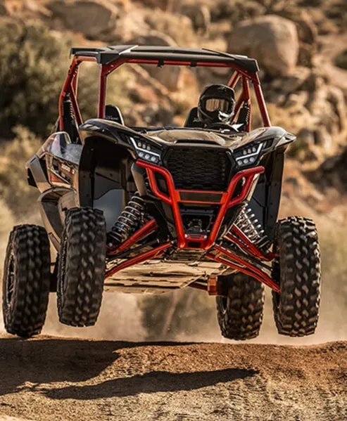
An all-terrain vehicle (ATV) is defined as a motorized off-road vehicle designed to travel on four low-pressure or non-pneumatic tires, having a seat designed to be straddled by the operator and handlebars/steering for control. ATVs are subdivided into two types as designated by the manufacturer.
- Type-1: ATVs designed with signal seat for operator only.
- Type-2: ATVs designed with seating position behind/beside operator seats.
BAJA SAE:
Baja SAE is a collegiate design series competition run by the Society of automotive engineers (SAE International). Teams of students from universities all over the world design and build small off-road cars. The cars all have engines of the same specifications. As of 2018 the engine has been an unmodified Briggs and Stratton Model 19 Vanguard engine single cylinder with a displacement of 305cc and power output of approximately 10 bhp (7.5 kW).
The goal in Baja SAE racing is to design, build and race off-road vehicles that can withstand the harshest elements of rough terrain. The vehicles used in Baja SAE racing are often similar in appearance to dune buggies. Before 2007, the events were called "Mini Baja."
Continuously Variable Transmission (CVT):
It is an advanced type of gearbox and part of many modern-day cars. As the name suggests, it varies the speed continuously instead of step-by-step as in an automatic gearbox. As a result, it makes the drive smoother than other transmission types. Basically, Continuously Variable Transmission is a type of automatic transmission. However, even without driving the vehicle and just looking at the gear lever, you will notice it is the same as a conventional automatic. It does the same thing as the automatic gearbox. It automatically converts the engine’s limited speed range to various ratios and sends it to the driven wheels using several different gears.
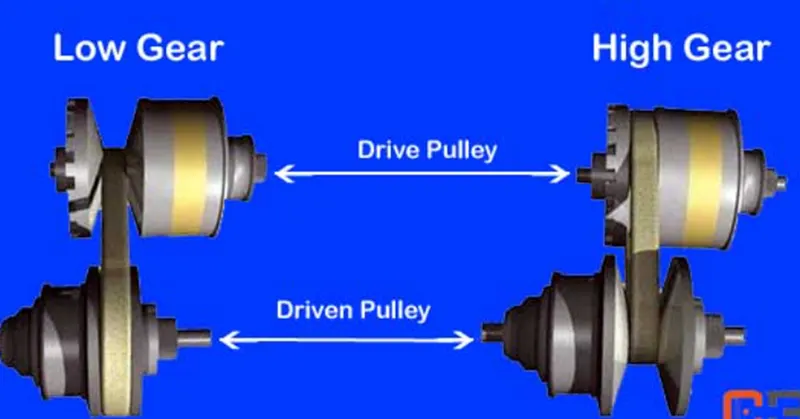
The main difference between the automatic transmission and CVT is the number of gears. The automatic gearbox is limited to 4 to 9 gear ratios. Besides, there are definite or noticeable changes between the gears, and you could feel this during driving. However, CVT has an infinite number of ratios ranging from low to high. It is because the transmission moves ‘sleeplessly’ through the gears according to the driving conditions. Even though manufacturers use the term infinite, the lowest ratio is close to the first gear in an automatic gearbox.
In contrast, the highest ratio is close to the highest gear in a standard gearbox. Not all continuously variable transmissions are the same. Some are designed for economy hatchbacks & sedans, while others are for vehicles with more powerful engines.
Main Components -
- Two Pulleys as a variable input pulley that spins from the power from the engine.
- An output pulley that sends the power to the driven wheels.
- A high power/density rubber or metal belt connects the two pulleys and varies the ratios between them as the vehicle is being driven.
Various microprocessors and sensors as the transmission must be able to detect the driving conditions.
Main Block:
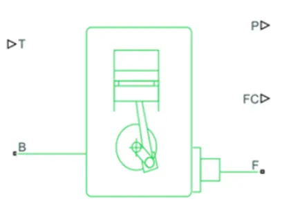
Generic Engine Block:
It represents a general internal combustion engine. This block is suitable for a generic engine for spark ignition and diesel. Speed -power and speed-torque parametrizations are provided. Using this block, we can calculate torque and speed through the block programmed formula by taking throttle signal as input. The block also engines power using a function of engine speed.
Main Ports:
- B (Rotational Conserving Port) - Representing the Engine Block (It should be connected to rotational motion reference).
- F (Rotational Conserving Port) - Representing the Engine Crankshaft.
- T (Physical Signal Input Port) - Specifying the normalized engine throttle level.
- P (Physical Signal Output Port) - Reporting the instantaneous engine power, in W.
- FC (Physical Signal Output Port) - Reporting the fuel consumption rate, in kg/s.
Simple Gear:
The Simple Gear block represents a gearbox that constrains the connected driveline axes of the base gear, B, and the follower gear, F, to corotate with a fixed ratio that is specified.
Main Ports:
- B (Base) - Rotational mechanical conserving port associated with the base, or input, shaft.
- F (Follower) - Rotational mechanical conserving port associated with the follower, or output, shaft.
Variable Ratio Transmission Block:
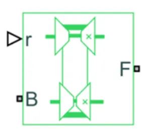
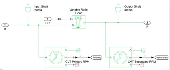
The Variable Ratio Transmission block represents a gearbox that dynamically transfers motion and torque between the two connected driveshaft axes, base and follower.
Ignoring the dynamics of transmission compliance, the driveshafts are constrained to corotate with a Variable Gear Ratio control that you control. You can choose whether the follower axis rotates in the same or opposite direction as the base axis. If they rotate in the same direction, ωF and ωB have the same sign. If they rotate in opposite directions, ωF and ωB have opposite signs.
Transmission compliance introduces internal time delay between the axis motions. Therefore, unlike a gear, a variable transmission does not act as a kinematic constraint. You can also control torque loss caused by transmission and viscous losses.
Main Ports:
- B – Base Pulley or Drive Pulley.
- F – Follower Pulley or Driven Pulley.
- r – Variable Transmission Ratio (Input).
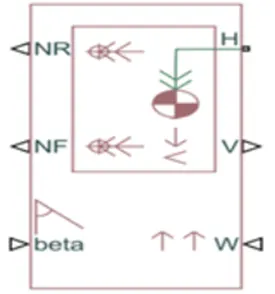
Vehicle Body block:
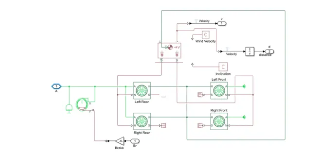
The Vehicle Body block represents a two-axle vehicle body in longitudinal motion. The vehicle can have the same or a different number of wheels on each axle. The vehicle wheels are assumed identical in size. The vehicle can also have a center of gravity (CG) that is at or below the plane of travel.The block accounts for body mass, aerodynamic drag, road incline, and weight distribution between axles due to acceleration and road profile. Optionally include pitch and suspension dynamics. The vehicle does not move vertically relative to the ground.The block has an option to include an externally-defined mass and an externally-defined inertia. The mass, inertia, and center of gravity of the vehicle body can vary over the course of simulation in response to system changes
Main Ports:
- Beta (Road Incline Angle) in rad - Physical signal input port for road incline angle.
- W (Head Wind Speed) in m/s - Physical signal input port for road incline angle.
- CG (Center of gravity) in m - Physical signal input port of externally defined mass relative to the CG of vehicle (only available with externally defined additional mass is set to on).
- M (Mass) in kg - Physical signal input port for mass of the externally defined mass (only available with externally defined additional mass is set to on)
- J (Externally defined moment of inertia) in kg*m^2 - Physical signal input port of the externally defined mass.
- NR (Rear Axle Normal Force) in N - Physical signal output port for the rear axle which is considered positive acting downward.
- NF (Front Axle Normal Force) in N - Physical signal output port for the front axle which is considered positive acting downward.
- V (Longitudinal Velocity) in m/s - Physical output signal of vehicle velocity.
- H (Horizontal Motion) - Conserving port related to the horizontal motion of vehicle body (tyres should be connected to this port).
Double Shoe Brake Block:
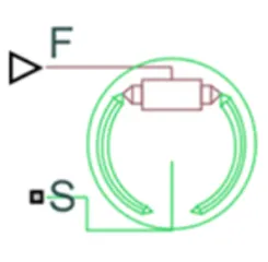
The Double-Shoe Brake block represents a frictional brake with two pivoted rigid shoes that press against a rotating drum to produce a braking action. The rigid shoes sit inside or outside the rotating drum in a diametrically opposed configuration. A positive actuating force causes the rigid shoes to press against the rotating drum. Viscous and contact friction between the drum and the rigid shoe surfaces cause the rotating drum to decelerate.
Main Ports:
- F - Physical signal input port associated with the applied actuating force.
- S - Rotational conserving port associated with the rotating drum shaft.
Tire (Magic Formula) Block:
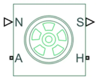
The Tire (Magic Formula) block models a tire with longitudinal behavior given by the Magic Formula, an empirical equation based on four fitting coefficients. The block can model tire dynamics under constant or variable pavement conditions.
The longitudinal direction of the tire is the same as its direction of motion as it rolls on pavement. This block is a structural component based on the Tire Road interaction block.
To increase the fidelity of the tire model, you can specify properties such as tire compliance, inertia, and rolling resistance. However, these properties increase the complexity of the tire model and can slow down simulation. Consider ignoring tire compliance and inertia if simulating the model in real time or if preparing the model for hardware-in-the-loop (HIL) simulation.
Main Port:
- N (Normal Force) - Physical signal input port associated with the normal force acting on the tire. The normal force is positive if it acts downward on the tire, pressing it against the pavement.
- S (Tire Slip) - Physical signal output port associated with the relative slip between the tire and road.
- A (Axle) - Mechanical rotational port associated with the axle that the tire sits on.
- H - Mechanical translational port associated with the wheel hub that transmits the thrust generated by the tire to the remainder of the vehicle.
Other Blocks –
- Solver Configuration – To specify the solver parameters before starting the simulation.
- Signal Builder – To input the Brake, Throttle and CVT Ratio.
- Simulink to PS Converter – To convert the Simulink signal to Simscape environment.
- PS to Simulink Converter – To convert Simscape signal to Simulink environment.
- Mechanical Reference – To make sure all the components are clamped to the ground.
- Rotational free end: The Rotational Free End block represents a mechanical rotational port that rotates freely, without torque.
- Scope – To display different graphs.
- Display – To view the calculated engine power.
- Inertia – To represent the solid inertia.
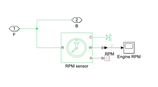
- Rotational Motion Sensor – To sense the rotational motion from the engine and give output as rpm.
- PS Terminator - Terminator for unconnected physical signal outputs.
- PS Constant - Generate constant physical signal.
- Rotational Free End – For mechanical component (Tire).
- Custom Measure Gauge – To measure the brake and throttle input.
- Knob – To increase, decrease and vice-versa of throttle and brake inputs.
- Lookup Table – To insert the CVT values from the workspace.
- Step – To increase or decrease an input value for a defined time interval.
Types Of Module Study:
- Study – 1: BAJA ATV model without dashboard.
- Study – 2: BAJA ATV model with dashboard.
- Study – 3: BAJA ATV model using the lookup table without a dashboard.
- Study – 4: BAJA ATV model using the lookup table with a dashboard.
Study – 1: BAJA ATV model without dashboard –
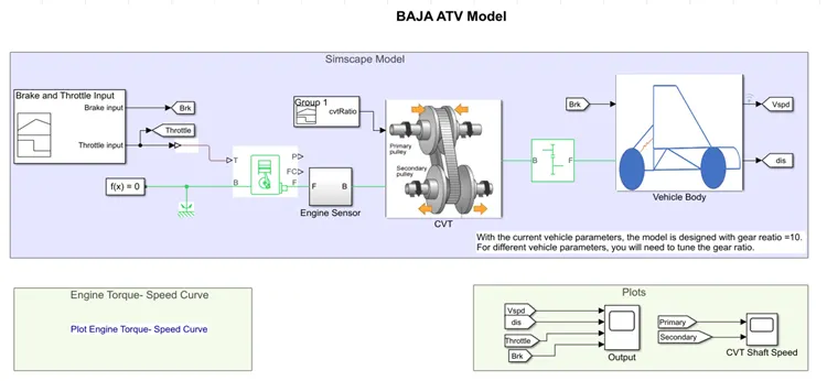
- Signal Builder Block is used to generate Throttle & Brake Signal, this signal is used as an Input for Generic Engine Block.
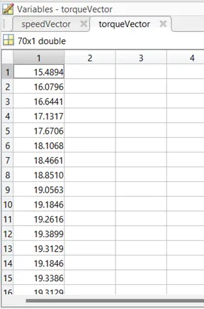
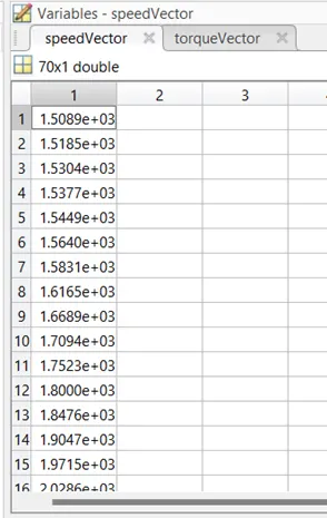
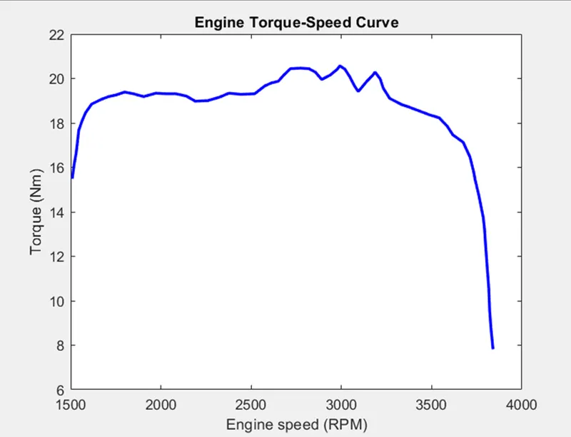
- Torque & Speed Vector are inputted from the Matlab Workspace.
- Engine Generate the output (RPM) which is taken from Crank Shaft output & this output will be given to the Engine Sensor (Ideal Rotational Motion Sensor) to sense the output (RPM).
- This same output signal is given to CVT (Variable Ratio Gear) Block & further given to Simple Gear Block.
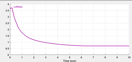
- CVT ratio is provided to CVT Block through Signal Builder.
- The speed is controlled by the variable CVT ratios and the controlled output speed is inputted to the vehicle axle.
- The brake signal is generated by the signal builder and inputted to the vehicle body (Double Shoe Brake) for applying the brake to axle.
- The power from the CVT is inputted to the axle and the vehicle accelerates according to the speed.
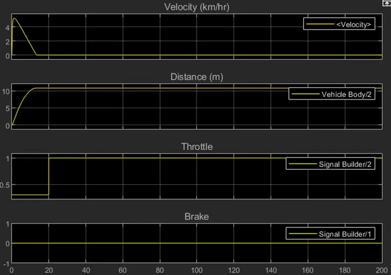
- Then the Velocity is taken as output from the vehicle body for further analysis.
Engine Sensor Block:
CVT Block:
Vehicle Body Block:
Brake & Throttle Input:
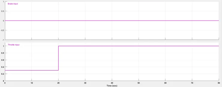
- No brake is provided.
- A constant throttle of 0.3 for the first 20 seconds, and full throttle of 1 for the remaining.
- These two parameters are fed into the engine.
CVT Ratio:
Torque and speed Matlab workspace input:
Scope Output:
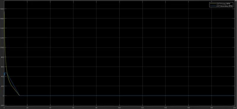
CVT Shaft RMP:
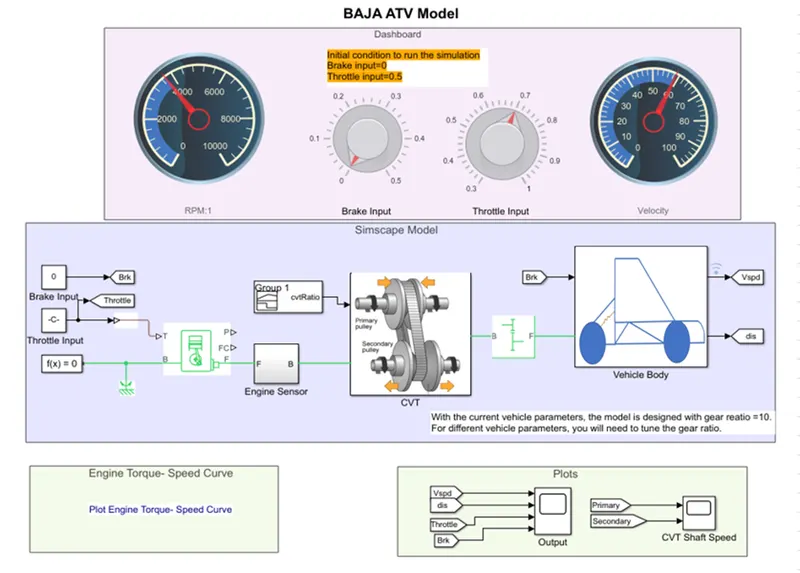
Study – 2: BAJA ATV model with dashboard.
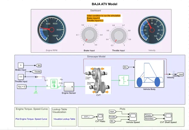
The Throttle & Brake Input are given through Dashboard instead of Signal Builder Block, apart from this remaining all block is same.The main intention behind the usage of the dashboard is to study the output value with the variation in the inputted values of throttle and brake which will give the value of rpm and velocity of the engine in the digital reading.
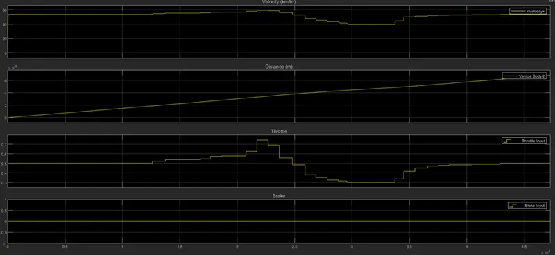
Scope - Output
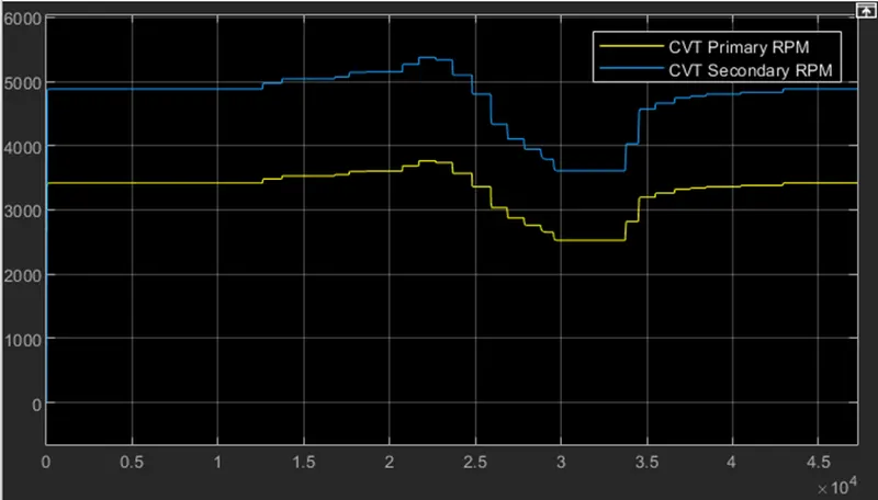
Scope – CVT Shaft Speed
Study – 3: BAJA ATV model using the lookup table without a dashboard.
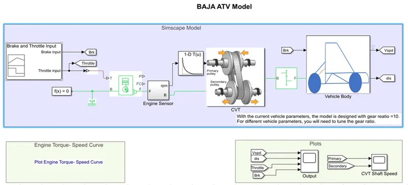
This Model is similar to Study – 1 model, the only difference is that instead of using CVT ratio signal builder block the 1-D Look Up Table has been used.
The 1-D Look up table calculate CVT ratio by cvtr as a table data & Speed value by speedV as a breakpoint1 data.
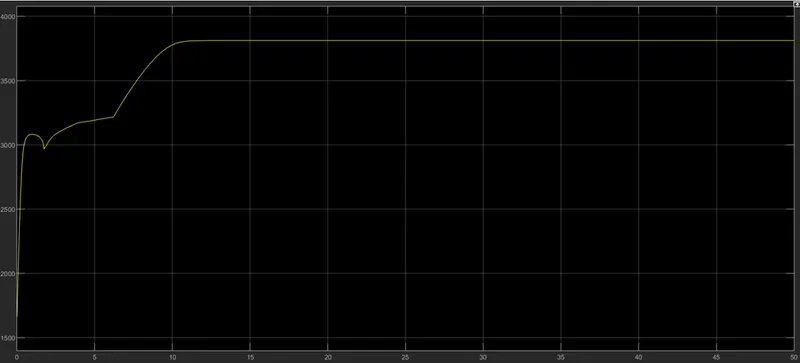
Engine RMP Output:
Engine Torque-Speed Curve:
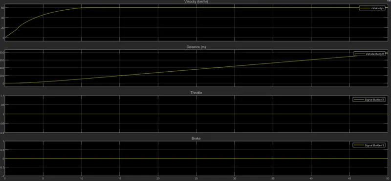
Scope Output:
CVT Shaft Speed:
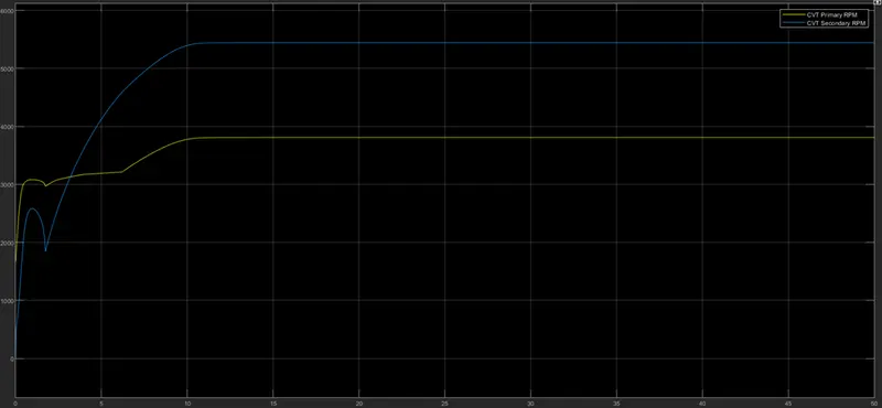
Study – 4: BAJA ATV model using the lookup table with a dashboard.
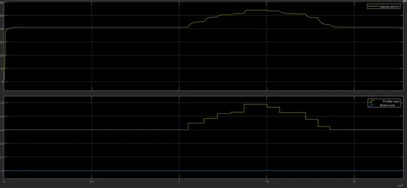
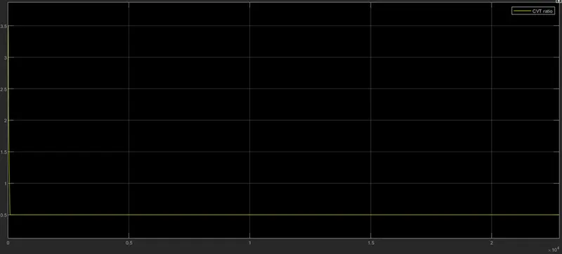
This Model is similar to Study 2 model, the only difference is that instead of using CVT ratio signal builder block the 1-D Look Up Table has been used.The lookup table is similar close to Study-3 lookup table. The only difference is the input signal as a vehicle velocity instead of engine RPM is used.
Scope Output:
CVT Output:
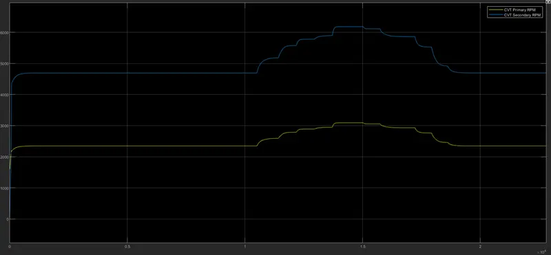
CVT Shaft Output:
Conclusion:
- Vehicle Performace can be observed under various provided condition.
- The Velocity, Engine Speed & CVT Shaft Speed are directly proportional to the Throttle input and inversely proportional to the Brake input.
- CVT Primary speed is greater than CVT Secondary speed as they are directly proportional to their shaft diameter.
- The Performace of Braking System & Throttle System easily observed.