Project
BAJA ALL TERRAIN VEHICLE (ATV) ANALYSIS USING SIMULINK - CVT
AIM: To Study And Analyse BAJA All Terrain Vehicle (ATV) using SIMULINK
OBJECTIVE: To prepare a technical report of BAJA ATV model
PLATFORM USED: MATLAB – SIMULINK
BAJA ALL TERRAIN VEHICLE (ATV)
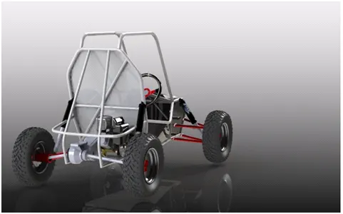
An all terrain vehicle (ATV) is defined as a motorised off-highway vehicle designed to travel on four low-pressure or non-pneumatic tires, having a seat designed to be straddled by a single operator and no passenger. As the name implies, an ATV can be operated at wide range of terrains that normal vehicles cant.
BAJA All Terrain vehicle is a collegiate design series competition run by the society of automotive engineers international ( SAE International) . Teams of students from universities all over the world design and build small off-road cars. The cars have engines of the same specifications. The goal in BAJA SAE racing is to design, build and race off-road vehicles that can withstand the harness elements of rough terrain.
MAIN COMPONENTS OF ATV
GENERIC ENGINE : Generic engine block is a simple Spark ignition (SI) or a Compression ignition (CI) Engine. The torque and power figures are provided.
Ports in Generic engine:
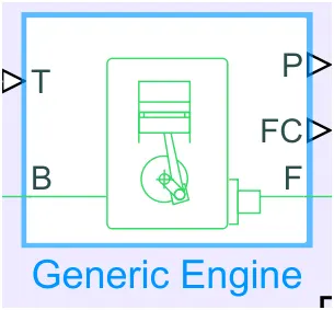
- F – Rotational conserving port - engine crank shaft
- B - Rotational conserving port – Engine block
- T - Physical signal input port – Engine throttle
- FC – Physical signal output- Fuel consumption
- P – Physical signal output – Instantaneous Engine power
VEHICLE BODY
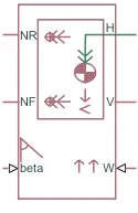
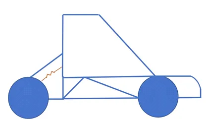
- NR- Rear axle normal force
- NF-Front Axle normal force
- Beta- Road incline angle
- H- Horizontal motion
- V-Longitudinal velocity
- W- Head wind speed
SIMPLE GEAR
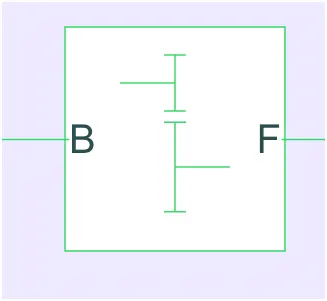
A simple gear is a combination of Driver & Driven which can reduce the speed with respect to the gear ratio.
gear ratio= (driven gear speed)/(driver gear speed)B - Driver gear
F- Driven gear
CVT TRANSMISSION
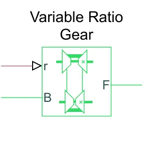
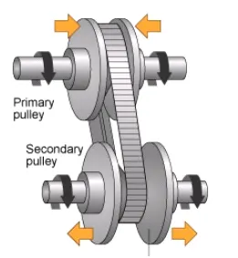
A continuous variable transmission is an automatic transmission that can change seamlessly through a continuous range of gear ratios.This contrast with other transmissions that provide a limited number of gear ratios in fixed steps. The flexibility of a CVT with suitable control may allow the engine to operate at a constant RPM while the vehicle moves at varying speeds. The most common type of CVT uses two pulleys connected by a belt or chain.
CVT ports
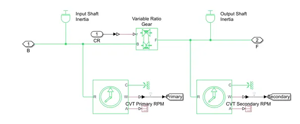
- B – Base or Driven pulley
- F- Follower or Driven
- r – Variable transmission ratio
TIRE
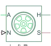
ATV has four tires which is connected to the axle to move the vehicle.
Tire ports
- A – Axle
- H – Mechanical translational port
- S - Tire slip
- N- Normal force
Double Shoe Brake
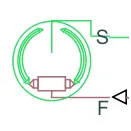
The double shoe brake block represents a frictional brake with two pivoted rigid shoes that press against a rotating drum to produce a braking action. The rigid shoes sit inside or outside the rotating drum in diametrically opposed configuration. A positive actuating force causes the rigid shoes to press against the rotating drum and rigid shoes surfaces cause the rotating drum to decelerate.
The double shoe brakes provides high braking torque with small actuator deflections in applications that include motor vehicles and some heavy machinery.
- F- Physical signal port – applied actual force
- S – Rotational conserving port – rotating drum shaft
Main Blocks Used
- Generic engine
- Simple gear
- Vehicle body
- Variable gear ratio
- Double shoe brakes
- Tire
- Signal builder
- Simulink to PS converter
- Scope
- Display
- PS to Simulink converter
- Inertia
- Solver configurations
- Rotational motion sensor
- PS constant
- PS Terminator
- Rotational free end
- Custom measure gauge
- Lookup table
- Step
- Knob
- Mechanical reference
MODELS
- BAJA ATV model with dashboard
- BAJA ATV model without dashboard
- BAJA ATV Model - lookup table
- BAJA ATV model - Mapped lookup table with dashboard
- BAJA ATV Model – mapped lookup table without dashboard
BAJA ATV MODEL WITHOUT DASHBOARD
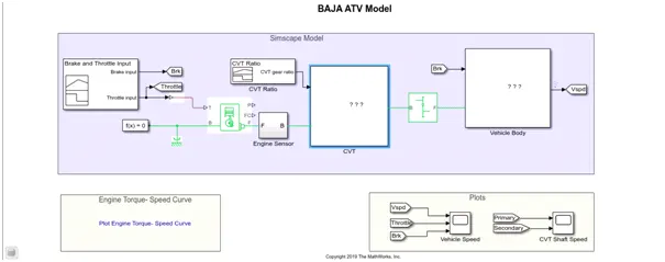
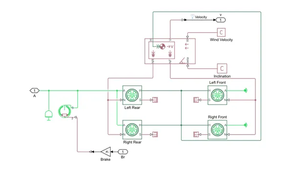
Main Model
CVT
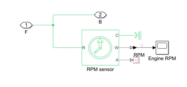
Engine sensor
Vehicle body
Methodology
- Throttle and brake input is generated using a signal builder
- Speed and torque inputs are given using workspace
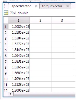
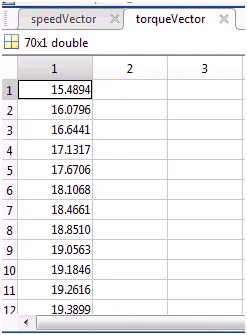
- Then the output RPM from the generic engine is sensed using a ideal rotational motion sensor
- CVT ratio is provided using a Signal builder and the RPM of driven and driver pulleys are sensed using ideal motion sensor
- Then the rotational motion is provided to simple gear from variable ratio gear, where the simple gear can be referred as the axle of the vehicle
- From simple gear the output Rotation or the speed is given to the tires
- The brake input signal is generated using a signal builder
- When the tire receives the output power through axle, the vehicle starts to accelerate
- The parameters of the vehicles bodies are set and the vehicle velocity taken as output
Result
Torque – speed plot
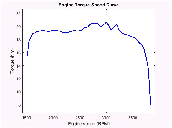
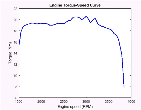
While analysing the curve, we can understand the engine produces maximum torque at 3000 range and Further the torque reduces.
CVT SHAFT SPEED
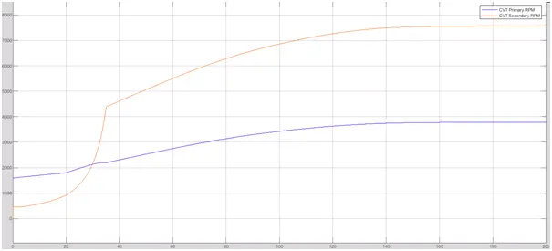
From the plot, we can determine the
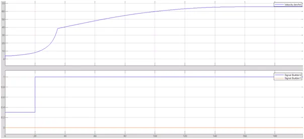
Vehicle speed vs throttle & brake input
BAJA ATV MODEL WITH DASHBOARD
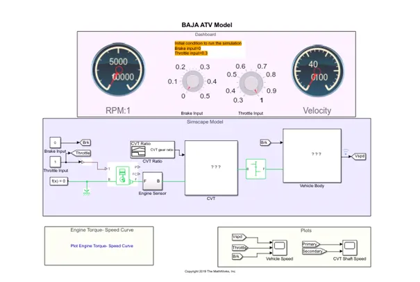
Main Model
Methodology
Here methodology is same as model without dashboard but the brake and throttle inputs are given by using knobs by manually.
Results
Engine torque- speed curve
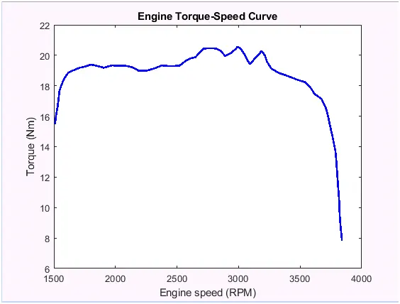
Engine toque speed curve is same as model without dashboard
Speed vs throttle and break input plot
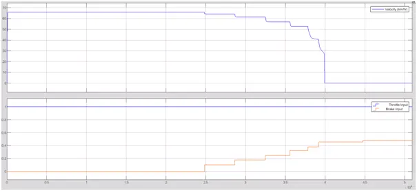
From the plot, we can understand that, at full throttle and zero break input, the vehicle has a maximum speed . and when break applies gradually, the vehicles reduces its speed and comes to stand still.
CVT SHAFT SPEED PLOT
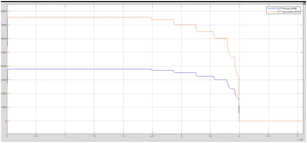
From the CVT shat plot, we can determine the gear ratio using the equation
gear ratio= (driven gear speed)/(driver gear speed)BAJA ATV MODEL – LOOK UP TABLE DATA
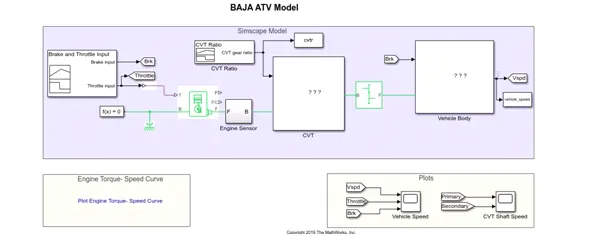
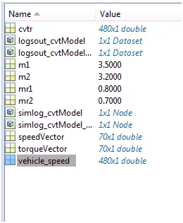
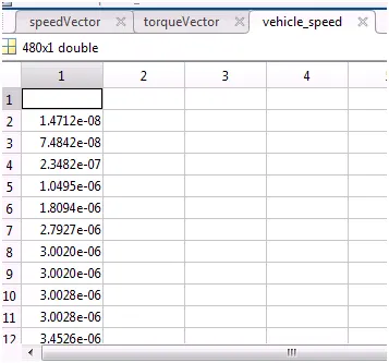
Methodology is same as model without dashboard but the data is extracted from the lookup table
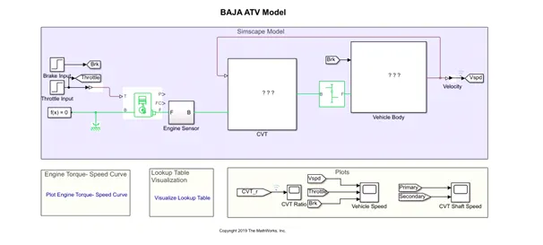
BAJA ATV MODEL- MAPPED WITHOUT DASHBOARD – LOOOKUP TABLE
Main model
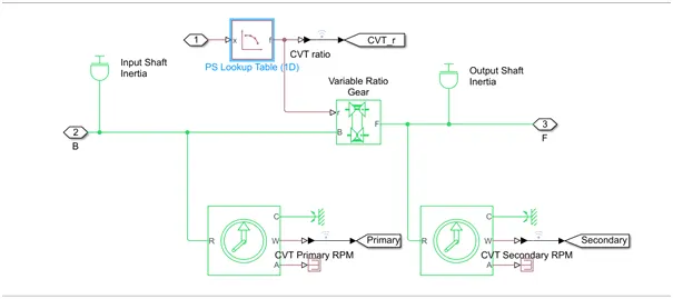
CVT
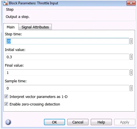
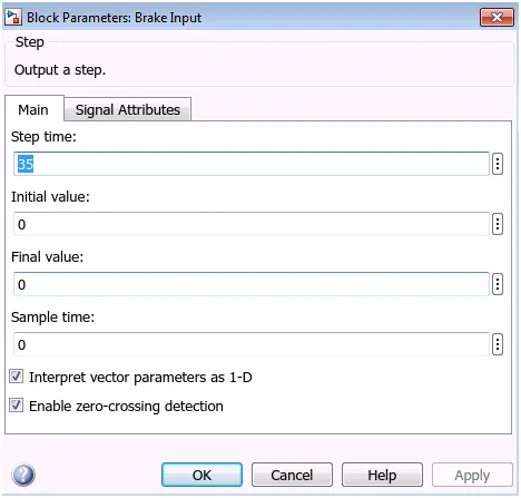
Methodology is same as BAJA model without dashboard . only difference here is the Brake and throttle is generated using a step signal
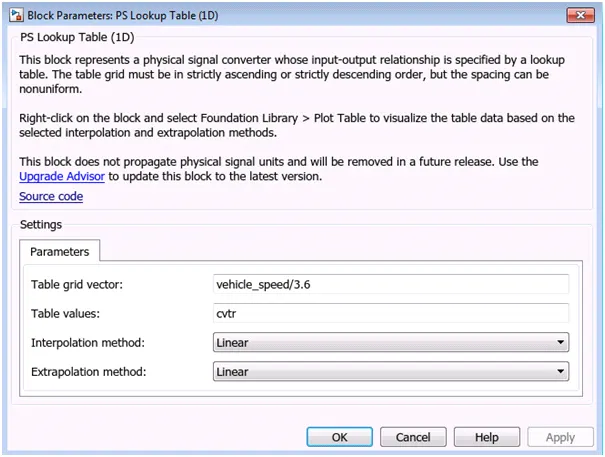
Here CVT ratio is given by using a 1D lookup table. When the CVT ratio changes the speed of the vehicle also changes.
Results
Engine Torque- speed curve
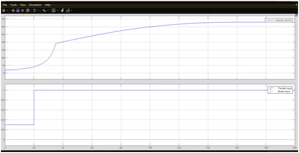
Vehicle speed vs Throttle & brake
CVT ratio vs Vehicle speed
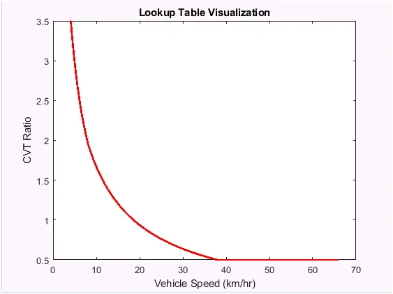
From the plot we can understand that the speed varies wrt the CVT ratio and attains a maximum speed at 0.5 CVT ratio
BAJA ATV MODEL – MAPPED WITH DASHBOARD – LOOKUP TABLE
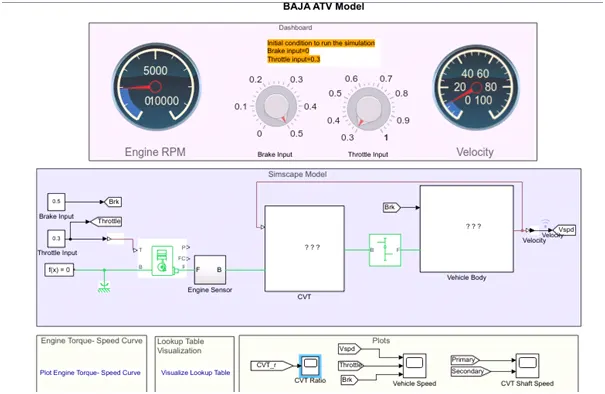
Methodology is same as BAJA ATV model mapped – lookup table, but here the brake and throttle is controlled using a knob and vehicle speed is given as feedback to CVT lookup table.
CVT Ratio plot
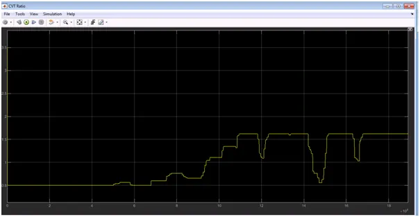
Results
Speed vs Break & Throttle
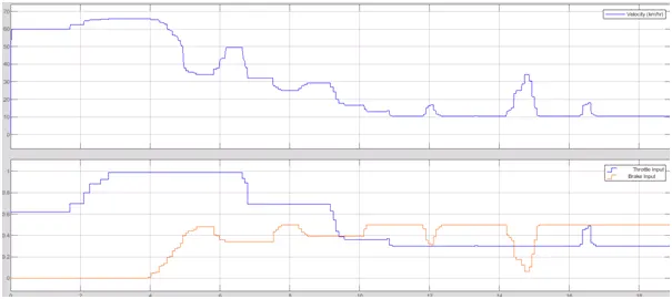
From the plot we can understand that speed varies with respect to the throttle and brake response.
CVT shaft speed plot
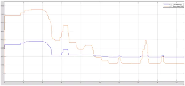
From this plot we can determine the engine speed and the Gear ratio varies with respect to the throttle and brake response
Simulink model : https://www.mathworks.com/matlabcentral/fileexchange/70576-baja-all-terrain-vehicle-atv-model