System Level Simulation of an ATV
Aim - Performing a system-level simulation of an All-terrain Vehicle.
Objectives:
- Carry out a system-level simulation of an ATV model which can be downloaded from the following link:
https://www.mathworks.com/matlabcentral/fileexchange/70576-baja-all-terrain-vehicle-atv-model - Prepare a technical report explaining the model properties and comments on the results.
ATV Model:
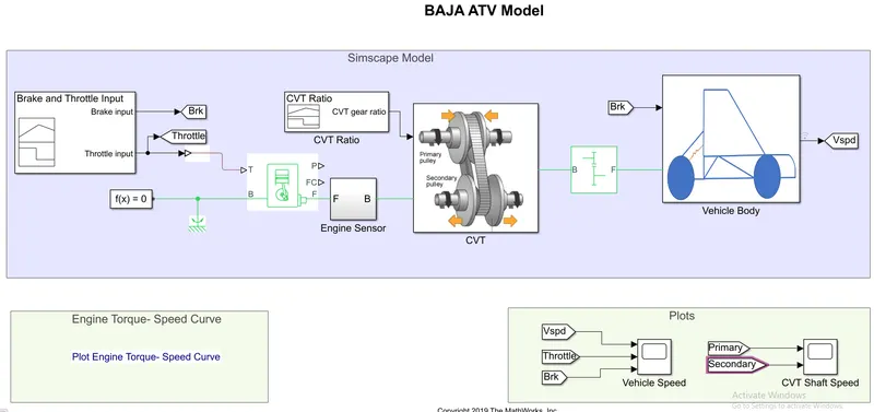
Model Properties:
- Brake and Throttle Input - It is a signal builder which provides one input for the brakes and the input for the throttle.
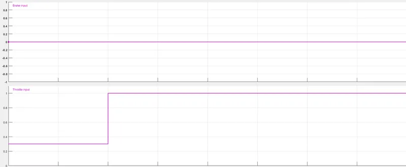
The brake input is simply a straight line which indicates that brakes are not being applied during the entire simulation.
The throttle input is 0.3 for the t 20 seconds which is increased to 1 which indicated that marginal throttle is provided initially and is then the throttle is applied after 20 seconds.
The throttle signal is fed into the generic engine block and the brake signal is fed into the vehicle body block. - Generic Engine Block - It is a generic engine block which represents a system-level model of spark ignition and diesel engine suitable for use at initial stages of modeling when only the basic parameters are available.
The Dynamics of the block are as follows: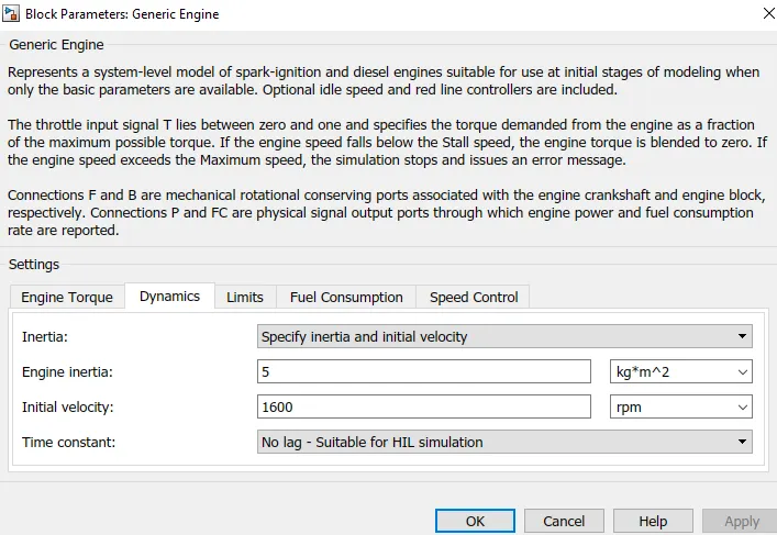
The output of the generic engine model goes into the engine sensor block. - Engine Sensor Block - It consists of an RPM sensor which is reflected in a scope. A mechanical rotational motion reference is also required in the model.
The input of the engine sensor block is passed to the CVT model as it is.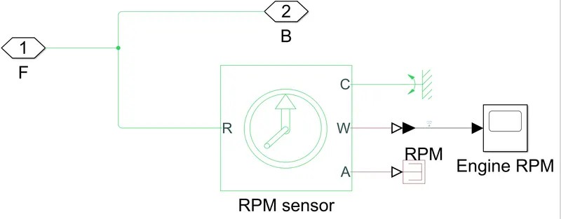
- CVT Ratio - This block is also a signal builder. The signal is of varying CVT ratio is also fed into the CVT block.
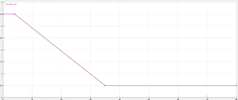
Initially, the CVT gear ratio is 3.5 which starts varying after around 5 seconds from 3.5 to 0.5. - CVT - This block represents the CVT ( Continuously Variable Transmission). Its main blocks are Variable Gear Ratio block and two Ideal Rotational Motion Sensors.
The output of the CVT block is the gear ratio after varying which is the input of a simple fixed gear block.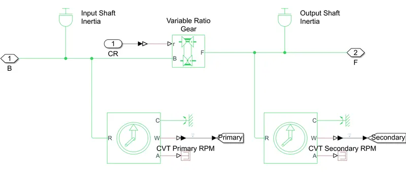
The variable-ratio transmission represents a variable ratio gearbox such as implemented by mechanical belt CVT, electric or hydraulic transmissions.
The ideal rotational motion sensors sense the CVT's RPMs of the primary and the secondary pulley.
The input and output shaft inertia are also provided to complete the CVT block. - Simple Gear - It represents a fixed gear ratio or gear box and no inertia or compliance is modeled in this block.
Its input is the output of the CVT and its output is fed into the vehicle body block.
The block parameters of this block are as follows: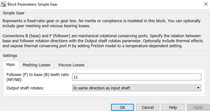
- Vehicle Body Block - This block consists of the braking system, tyres and the vehicle body block.
The inputs for this block are the brake signal and the output of the gear box and the output of this block is the Vehicle Speed.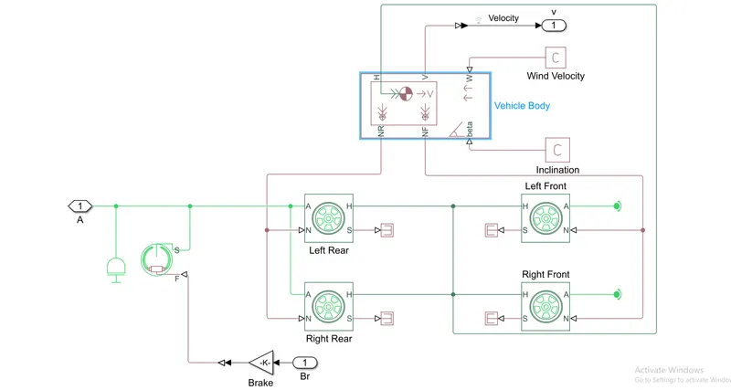
For braking, a Double-Shoe Brake block is used which represents a two-axle vehicle body in longitudinal motion. The block accounts for the vehicle mass, aerodynamic drag, road inclination and weight distribution between axles due to acceleration and road profile.
Tire blocks represent the longitudinal behaviour of a highway tire characterized by tyre-road interaction (Magic Formula) and simscape foundation library wheel and axle blocks.
The vehicle body model represents a two-axle vehicle body in longitudinal motion. This block also accounts for the vehicle mass, aerodynamic drag, road inclination and weight distribution between axles due to acceleration and road profile. Wind velocity and road inclination values are provided by separate blocks.
Results:
- Engine Torque-Speed Curve:
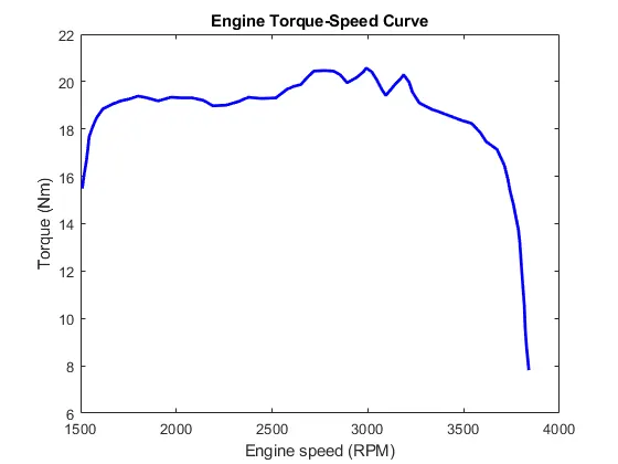
When the vehicle is starting from the rest position, there is a higher torque required to overcome the inertia of the vehicle.
It can be seen clearly in the above plot that the engine torque is higher initially for the same reason and when the vehicle comes into motion, the engine torque is almost constant for some time.
But as the engine RPM increases sharply, the engine torque increases marginally and at certain RPM it drops sharply. - CVT Shaft Speed:
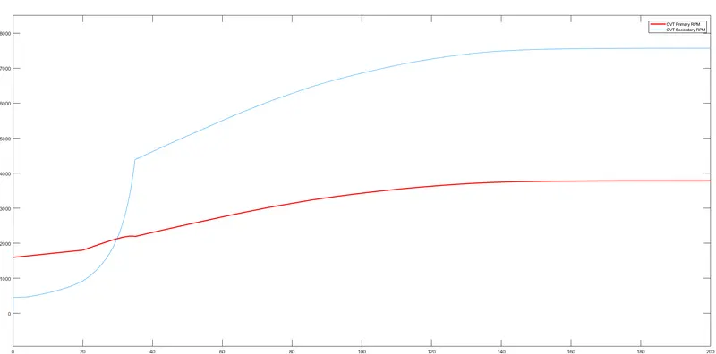
The red line represents the RPM of the primary pulley of the CVT and blue represents the RPM of the secondary pulley of the RPM. It can be observed that in the initial steps the primary pulley's RPM is higher and the secondary pulley's RPM are lower due to higher torque requirement because the vehicle needs higher torque to change its state from rest to motion.
The secondary pulley's RPM increases almost parabolically because higher torque requirement starts to reduce when the vehicle comes in motion.
Finally, the RPM of secondary pulley increases sharply and then increases gradually over time when the vehicle achieves higher speed. - Vehicle Speed:
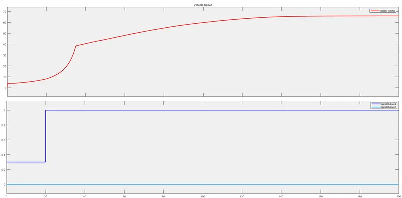
The above plot is divided into two halves. The upper half represents the Vehicle Speed (km/hr) with a red line and the lower half represents the input signals. The purple line represents the throttle and the sky-blue line represents the brake signal.
The initial throttle input is 0.3 for the first 20 seconds and its effect can be seen from the vehicle speed plot where the speed increases at a very slow rate.
But after 20 seconds when the throttle signal is 1, the vehicle speed increases sharply.
After reaching a speed of around 40 km/hr, the acceleration is reduced. Although the speed increases continuously after crossing 40 km/hr, the acceleration is not very high and it increases at a slower rate.
CVT Dashboard Model: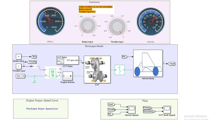
This is the CVT dashboard model using which we can provide the brake and throttle input in real-time and visualize the same. The rest of the model is the same except for the brake and throttle signal which are provided by the user during the simulation.
The initial condition set to run the simulation sets the brake input to 0 and the throttle input to 0.3.
The Brake Input knob is used to control the brakes and the Throttle input knob is used to control the throttle.
The circular gauge on the left displays the Engine RPMs when it is changed by the throttle and the brake inputs in real time and the similar gauge on the right displays the Vehicle velocity in real time simulation.