Project
~Aim:--
To prepare a technical report of Simulation of BAJA All-Terrain Vehicle (ATV) under different conditions.
~The following are the conditions we have to look and it is shown below
- CVT Model With Dashboard.
- CVT Model Without Dashboard.
- CVT Model With Dahboard(with Lookup table).
- CVT Model Without Dashboard(With Lookup table).
~Objectives:--
Carry out a Simulink model of All-Terrain Vehicle(ATV) and Prepare a technical report explaining the model properties & comments on the results.
~Now we will see What is an All-Terrain Vehicle:--
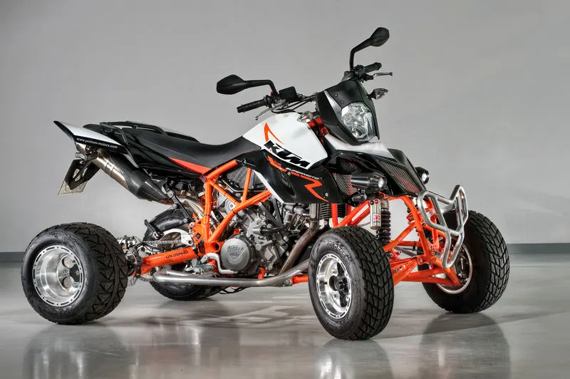
An all-terrain vehicle (ATV) is defined as a motorized off-highway vehicle designed to travel on four low-pressure or non-pneumatic tires, having a seat designed to be straddled by the operator and handlebars for steering control. The following picture shows the All-terrain(ATV)
~Advantages of an ATV:--
- All Terrain. One of the clearest advantages of investing in an all-terrain vehicle is its ability to tackle all terrains
- Handling. ATVs are great for more than climbing hills — they can also be incredibly maneuverable
- Simple Maintenance
- Versatility
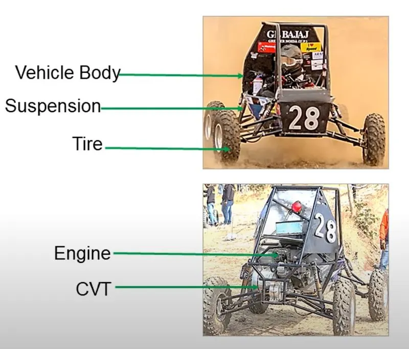
~The All-Terrain Vehicle Model of BAJA Model is shown below:--
~Basically these are the following Components of BAJA Vehicle
~ The Simulink Model for BAJA ATV model with Continuously Variable Transmission(CVT) Is As Shown below
Basically there are four following are the conditions (Cases) we have to look and it is shown below
- CVT Model With Dashboard.
- CVT Model Without Dashboard.
- CVT Model With Dahboard(with Lookup table).
- CVT Model Without Dashboard(With Lookup table).
#Sate1:--
#Condition 1:--
~~CVT Model with DashBoard:--
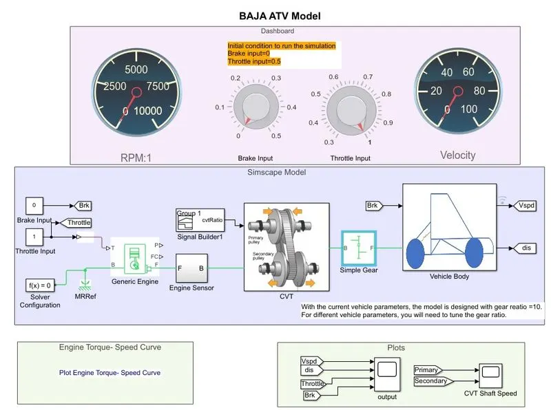
~The Blocks we have used are :--
- Custom Gauge(2)
- Knob(2)
- Signal Builder
- Generic Engine
- Engine Sensor
- Simple Gear
- Solver configuration
- Mechanical reference
- Constants(2)
- CVT Blockset (CVT Subsystem)
- Vehicle Body
- Scope(2)
- Engine torque Speed curve
~Now we will Gothrough the above Mentioned Blocks:--
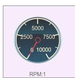
- Custom Gauge(2):--
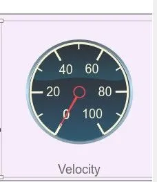
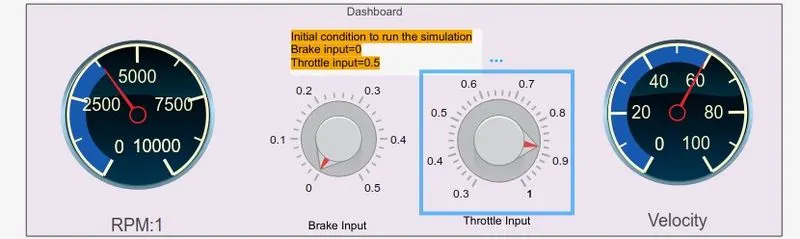
It Displays an input value on a customized gauge, here we have used two gauges
one is connected for RPM Sensor and the second is connected to Velocity signal and the Block is shown below.
- Knob(2):--
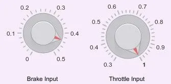
Basically Knob is used to set a value to tune parameter or a variable and we have used two knobs
one is connected to the Break input value and another is connected to Throttel input value,And it is shown in the below figure
- Signal Builder :--
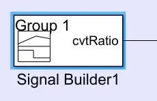
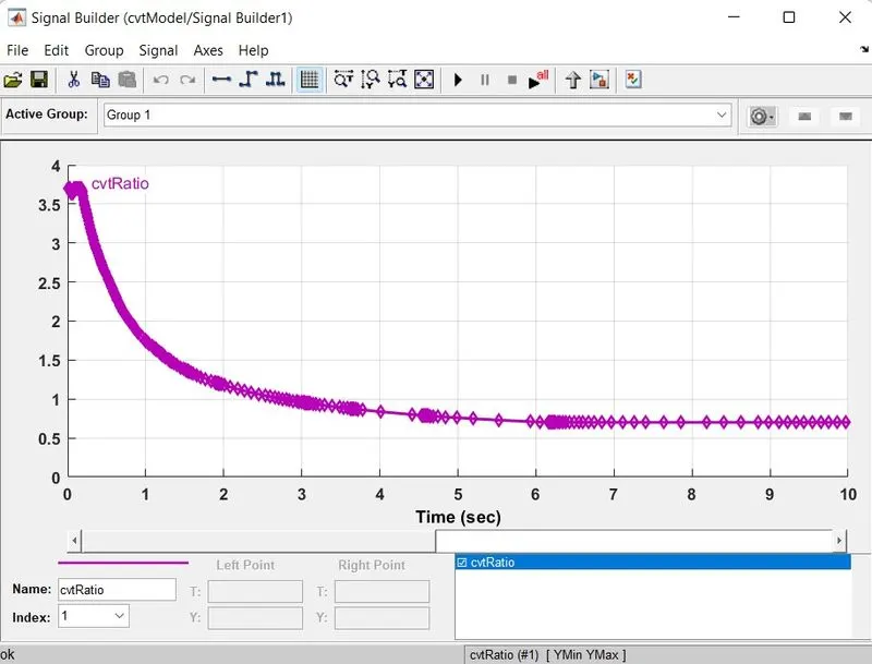
The Signal Builder block allows you to create interchangeable groups of piecewise linear signal sources, here in this Model we have used signal block for CVT ratio and it is shown below
- Generic Engine:--
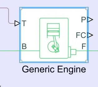
Represents a system-level model of spark-ignition and diesel engines suitable for use at initial stages of modeling when only the basic parameters are available. Optional idle speed and red line controllers are included.
The throttle input signal T lies between zero and one and specifies the torque demanded from the engine as a fraction of the maximum possible torque. If the engine speed falls below the Stall speed, the engine torque is blended to zero. If the engine speed exceeds the Maximum speed, the simulation stops and issues an error message.
Connections F and B are mechanical rotational conserving ports associated with the engine crankshaft and engine block, respectively. Connections P and FC are physical signal output ports through which engine power and fuel consumption rate are reported.
- Engine Sensor:--
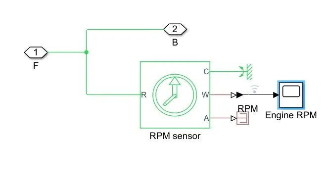
we have created the engine sensor subsytem inside this subsystem the RPM Sensor Block used and that is connected to the Throttel Gauge
- Simple Gear:--
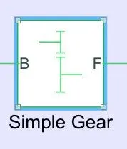
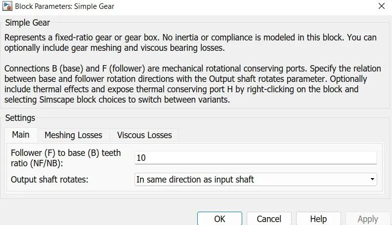
Represents a fixed-ratio gear or gear box. No inertia or compliance is modeled in this block. You can optionally include gear meshing and viscous bearing losses.Connections B (base) and F (follower) are mechanical rotational conserving ports. Specify the relation between base and follower rotation directions with the Output shaft rotates parameter. Optionally include thermal effects and expose thermal conserving port H by right-clicking on the block and selecting Simscape block choices to switch between variants. and here we have used 10 gears
- Solver configuration:--
Defines solver settings to use for simulation.
- Mechanical reference:--
This block represents a mechanical rotational reference point, that is, a frame or a ground. Use it to connect mechanical rotational ports that are rigidly affixed to the frame (ground).
- Constants(2):--
Output the constant specified by the 'Constant value' parameter. If 'Constant value' is a vector and 'Interpret vector parameters as 1-D' is on, treat the constant value as a 1-D array. Otherwise, output a matrix with the same dimensions as the constant value.
- CVT Blockset (CVT Subsystem):--
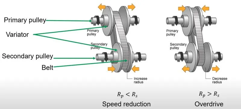
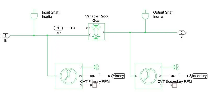
CVT is nothing but Continious Variable Transmission,A continuously variable transmission (CVT) is an automatic trasmission that can change seamlessly through a continuous range of gear ratio This contrasts with other transmissions that provide a limited number of gear ratios in fixed steps. The flexibility of a CVT with suitable control may allow the engine to operate at a constant RPM while the vehicle moves at varying speeds. and when the variator of the primary pulley is moved outwards then the variator of the secondary pulley moves inwards then it leads to the speed reduction, and similarlly when the variator of the primary pulley moves inwards and the variator of the secondar pulley moves outwards then this leads to over drive and this had been shown in the below figure and even the subsystem is also shown below
~Subsystem for the Continious Variable Transmission(CVT):--
- Vehicle Body:--
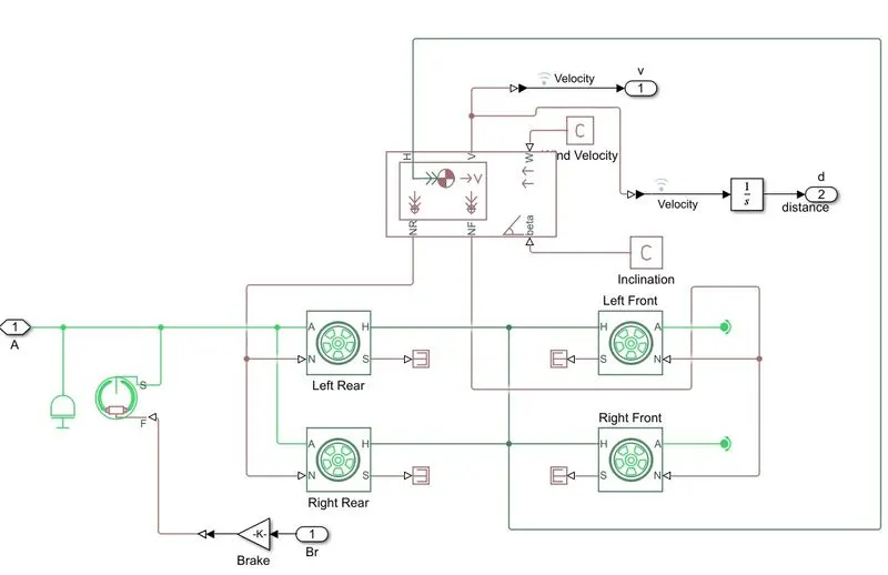
The vehicle body could be the main supporting structure or its particular element. The Vehicle Body of a modern car consists of an engine section, saloon, trunk. The vehicle body is the main supporting structure of a vehicle, to which all other components are attached.basically here we have a subsystem called vehicle body and that subsystem is as shown below
- Scope(2):--
Scope is used to show the output results
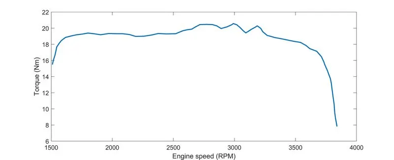
- Engine torque Speed curve :--
~Now let us run the model and see the Output:--
~Now we have to change the CVT ratio ie,signal Bulider block for the output and the signal builder block is shown below:--
~Now we have to change the Throttle input and break input knobs so that there is change in throttle and break outputs and these can be done by changing the knob values and as this cahnge the RPM and Velocity also varies and the figure shows the Blocks
~Now lets see what is the happening inside the CVT subsystem:--
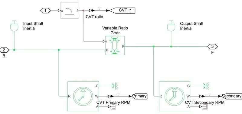
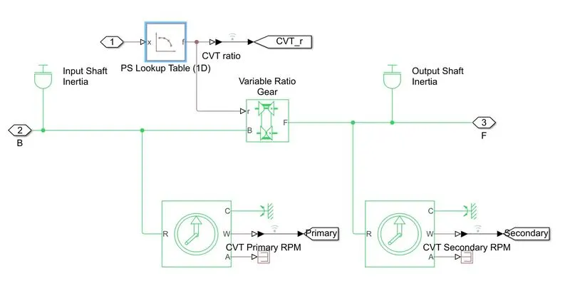
Here in the above figure shows the inertia of input and output shaft is reperesting the primary and secondary pulley and to specify the ratio we have used the gear ratio block and the two motion sensors are used to show the CVT primary RPM and CVT secondaryRPM
~Simple Gear ratio :--
To reduce the speed of the engine we have used the simple gear ratio and the gear ratio is 10 and it is shown in the below block and With the current vehicle parameters, the model is designed with gear ratio =10.For different vehicle parameters, you will need to tune the gear ratio.
~Now we will look into the vehicle body subsystem:--
Basically the vehicle body consist of vehicle body where we can specify mass wheels pe axil and etc and the tyre models
~Now we will see the outputs after chaniging the throttel and the brake inputs from the knobs:--
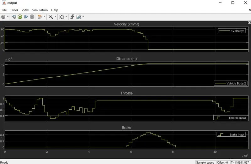
The above scope output shows the velocity,distance,throttel,and the break outputs
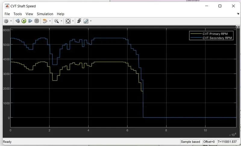
the above output shows the CVT speed , the blue line represents the CVT Secondary RPM and the yellow line represents the CVT primary RPM
#Sate1:--
#Condition 2:--
~~CVT Model without DashBoard:--
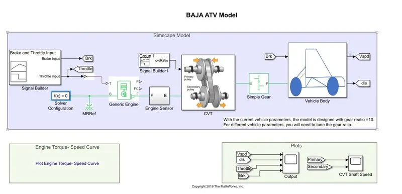
~The Blocks we have used are :--
- Signal Builder BLock(3)
- Generic Engine
- Engine Sensor
- Simple Gear
- Solver configuration
- Mechanical reference
- Constants(2)
- CVT Blockset (CVT Subsystem)
- Vehicle Body
- Scope(2)
- Engine torque Speed curve
~Now we will Gothrough the above Mentioned Blocks:--
- Signal Builder :--
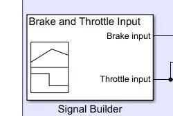
The Signal Builder block allows you to create interchangeable groups of piecewise linear signal sources, here in this Model we have used 3 signal block 1 for CVT ratio,Break and Throttle Inputs and the are as shown below
- Generic Engine:--
Represents a system-level model of spark-ignition and diesel engines suitable for use at initial stages of modeling when only the basic parameters are available. Optional idle speed and red line controllers are included.
The throttle input signal T lies between zero and one and specifies the torque demanded from the engine as a fraction of the maximum possible torque. If the engine speed falls below the Stall speed, the engine torque is blended to zero. If the engine speed exceeds the Maximum speed, the simulation stops and issues an error message.
Connections F and B are mechanical rotational conserving ports associated with the engine crankshaft and engine block, respectively. Connections P and FC are physical signal output ports through which engine power and fuel consumption rate are reported.
- Engine Sensor:--
we have created the engine sensor subsytem inside this subsystem the RPM Sensor Block used and that is connected to the Throttel Gauge
- Simple Gear:--
Represents a fixed-ratio gear or gear box. No inertia or compliance is modeled in this block. You can optionally include gear meshing and viscous bearing losses.Connections B (base) and F (follower) are mechanical rotational conserving ports. Specify the relation between base and follower rotation directions with the Output shaft rotates parameter. Optionally include thermal effects and expose thermal conserving port H by right-clicking on the block and selecting Simscape block choices to switch between variants. and here we have used 10 gears
- Solver configuration:--
Defines solver settings to use for simulation.
- Mechanical reference:--
This block represents a mechanical rotational reference point, that is, a frame or a ground. Use it to connect mechanical rotational ports that are rigidly affixed to the frame (ground).
- Constants(2):--
Output the constant specified by the 'Constant value' parameter. If 'Constant value' is a vector and 'Interpret vector parameters as 1-D' is on, treat the constant value as a 1-D array. Otherwise, output a matrix with the same dimensions as the constant value.
- CVT Blockset (CVT Subsystem):--
CVT is nothing but Continious Variable Transmission,A continuously variable transmission (CVT) is an automatic trasmission that can change seamlessly through a continuous range of gear ratio This contrasts with other transmissions that provide a limited number of gear ratios in fixed steps. The flexibility of a CVT with suitable control may allow the engine to operate at a constant RPM while the vehicle moves at varying speeds. and when the variator of the primary pulley is moved outwards then the variator of the secondary pulley moves inwards then it leads to the speed reduction, and similarlly when the variator of the primary pulley moves inwards and the variator of the secondar pulley moves outwards then this leads to over drive and this had been shown in the below figure and even the subsystem is also shown below
~Subsystem for the Continious Variable Transmission(CVT):--
- Vehicle Body:--
The vehicle body could be the main supporting structure or its particular element. The Vehicle Body of a modern car consists of an engine section, saloon, trunk. The vehicle body is the main supporting structure of a vehicle, to which all other components are attached.basically here we have a subsystem called vehicle body and that subsystem is as shown below
- Scope(2):--
Scope is used to show the output results
- Engine torque Speed curve :--
~Now let us run the model and see the Output:--
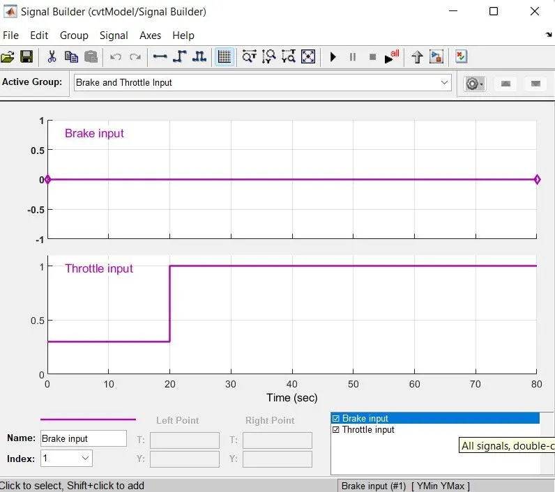
~Now we have to change the CVT ratio,Break and Throttle inputs ie,signal Bulider block for the output and the signal builder block is shown below:--
~Now lets see what is the happening inside the CVT subsystem:--
Here in the above figure shows the inertia of input and output shaft is reperesting the primary and secondary pulley and to specify the ratio we have used the gear ratio block and the two motion sensors are used to show the CVT primary RPM and CVT secondaryRPM
~Simple Gear ratio :--
To reduce the speed of the engine we have used the simple gear ratio and the gear ratio is 10 and it is shown in the below block and With the current vehicle parameters, the model is designed with gear ratio =10.For different vehicle parameters, you will need to tune the gear ratio.
~Now we will look into the vehicle body subsystem:--
Basically the vehicle body consist of vehicle body where we can specify mass wheels pe axil and etc and the tyre models
~Now lets run and see the output after Changing the Throttle,Break and CVT inputs
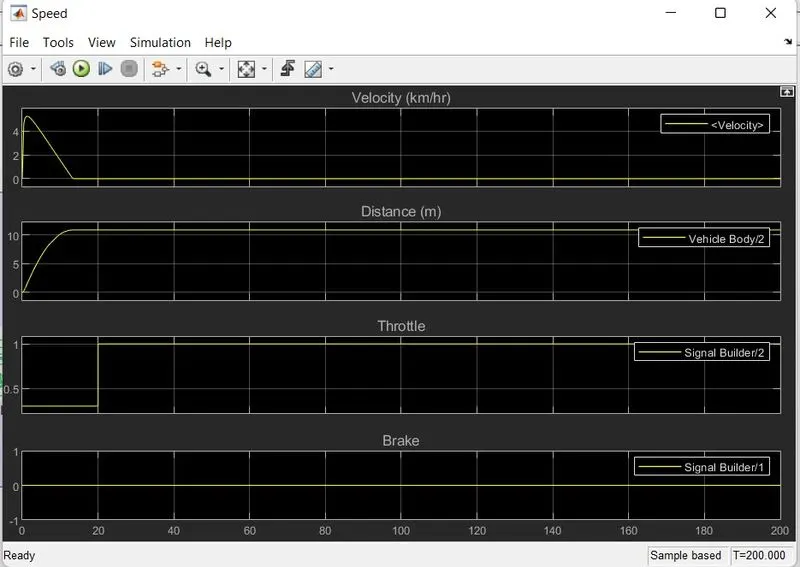
the above figure shows the velocity,distance throttle and break outputs
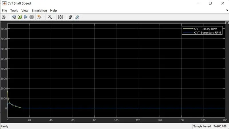
Above figure shows the primary and secondary CVT RPM and the Blue line represents the Secondary RPM and the yellow line Represents the Primary RPM
#State2:--
#Condition 1:--
~~CVT Model With Dahboard(with Lookup table):--
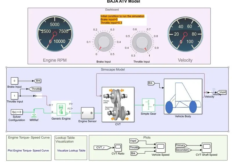
~The Blocks we have used are :--
- Custom Gauge(2)
- Knob(2)
- Lookup Table Visualization curve
- Generic Engine
- Engine Sensor
- Simple Gear
- Solver configuration
- Mechanical reference
- Constants(2)
- CVT Blockset (CVT Subsystem)
- Vehicle Body
- Scope(2)
- Engine torque Speed curve
- Break input
- Throttle input
~Now we will Gothrough the above Mentioned Blocks:--
- Custom Gauge(2):--
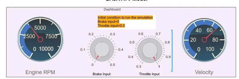
It Displays an input value on a customized gauge, here we have used two gauges
one is connected for RPM Sensor and the second is connected to Velocity signal and the Block is shown below.
- Knob(2):--
Basically Knob is used to set a value to tune parameter or a variable and we have used two knobs
one is connected to the Break input value and another is connected to Throttel input value,And it is shown in the below figure
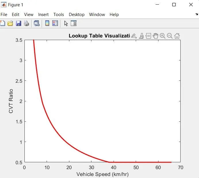
- Lookup Table Visualization curve:--
- Generic Engine:--
Represents a system-level model of spark-ignition and diesel engines suitable for use at initial stages of modeling when only the basic parameters are available. Optional idle speed and red line controllers are included.
The throttle input signal T lies between zero and one and specifies the torque demanded from the engine as a fraction of the maximum possible torque. If the engine speed falls below the Stall speed, the engine torque is blended to zero. If the engine speed exceeds the Maximum speed, the simulation stops and issues an error message.
Connections F and B are mechanical rotational conserving ports associated with the engine crankshaft and engine block, respectively. Connections P and FC are physical signal output ports through which engine power and fuel consumption rate are reported.
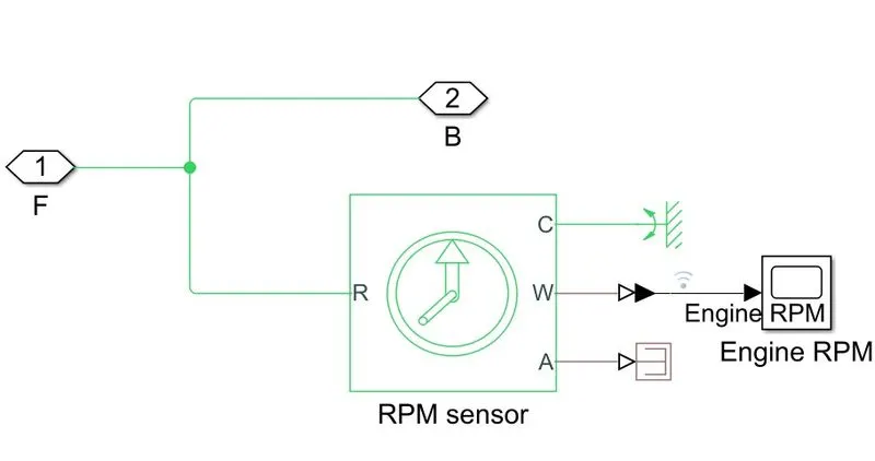
- Engine Sensor:--
we have created the engine sensor subsytem inside this subsystem the RPM Sensor Block used and that is connected to the Throttel Gauge
- Simple Gear:--
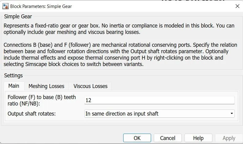
Represents a fixed-ratio gear or gear box. No inertia or compliance is modeled in this block. You can optionally include gear meshing and viscous bearing losses.Connections B (base) and F (follower) are mechanical rotational conserving ports. Specify the relation between base and follower rotation directions with the Output shaft rotates parameter. Optionally include thermal effects and expose thermal conserving port H by right-clicking on the block and selecting Simscape block choices to switch between variants. and here we have used 12 gears
- Solver configuration:--
Defines solver settings to use for simulation.
- Mechanical reference:--
This block represents a mechanical rotational reference point, that is, a frame or a ground. Use it to connect mechanical rotational ports that are rigidly affixed to the frame (ground).
- Constants(2):--
Output the constant specified by the 'Constant value' parameter. If 'Constant value' is a vector and 'Interpret vector parameters as 1-D' is on, treat the constant value as a 1-D array. Otherwise, output a matrix with the same dimensions as the constant value.
- CVT Blockset (CVT Subsystem):--
CVT is nothing but Continious Variable Transmission,A continuously variable transmission (CVT) is an automatic trasmission that can change seamlessly through a continuous range of gear ratio This contrasts with other transmissions that provide a limited number of gear ratios in fixed steps. The flexibility of a CVT with suitable control may allow the engine to operate at a constant RPM while the vehicle moves at varying speeds. and when the variator of the primary pulley is moved outwards then the variator of the secondary pulley moves inwards then it leads to the speed reduction, and similarlly when the variator of the primary pulley moves inwards and the variator of the secondar pulley moves outwards then this leads to over drive and this had been shown in the below figure and even the subsystem is also shown below
~Subsystem for the Continious Variable Transmission(CVT):--
- Vehicle Body:--
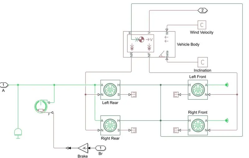
The vehicle body could be the main supporting structure or its particular element. The Vehicle Body of a modern car consists of an engine section, saloon, trunk. The vehicle body is the main supporting structure of a vehicle, to which all other components are attached.basically here we have a subsystem called vehicle body and that subsystem is as shown below
- Scope(2):--
Scope is used to show the output results
- Engine torque Speed curve :--
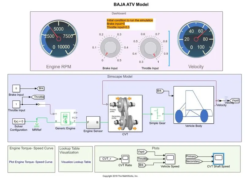
~Now let us run the model and see the output:--
~Simple Gear ratio :--
To reduce the speed of the engine we have used the simple gear ratio and the gear ratio is 10 and it is shown in the below block and With the current vehicle parameters, the model is designed with gear ratio =12 .For different vehicle parameters, you will need to tune the gear ratio.
~Now we will look into the vehicle body subsystem:--
Basically the vehicle body consist of vehicle body where we can specify mass wheels pe axil and etc and the tyre models
~Now we will see the outputs after chaniging the throttle and the brake inputs from the knobs:--
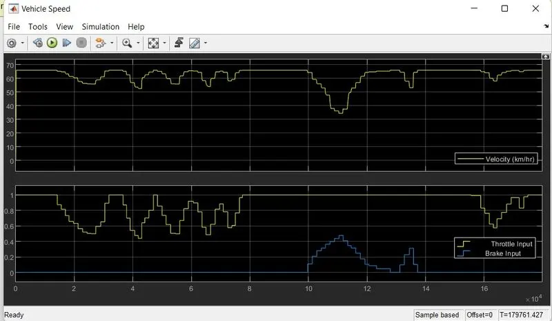
The Velocity,Throttel and break input has been shown in the above curve
~Now lets see the CVT ratio output
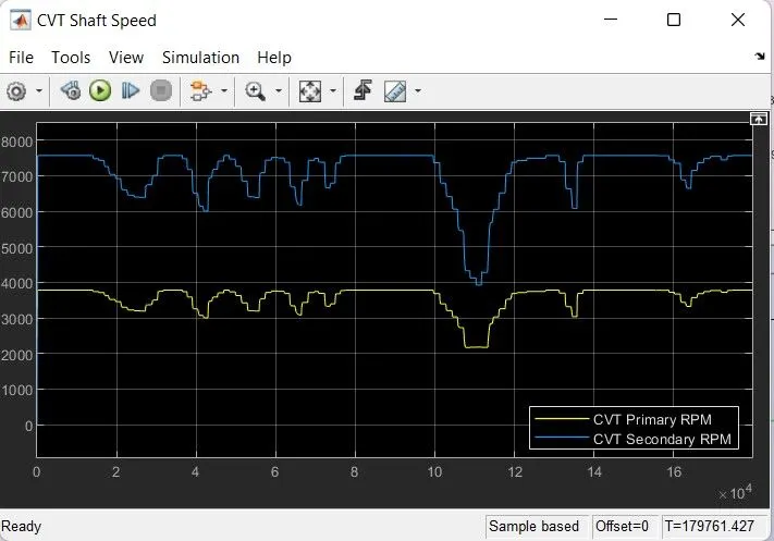
The above figure shows the CVT primary and secondary curve RPM and the yellow line shows the primary RPM and the blue line represents secondary RPM and this has been run for inf time
#State2:--
#Condition 2:--
~~CVT Model Without Dahboard(with Lookup table):--
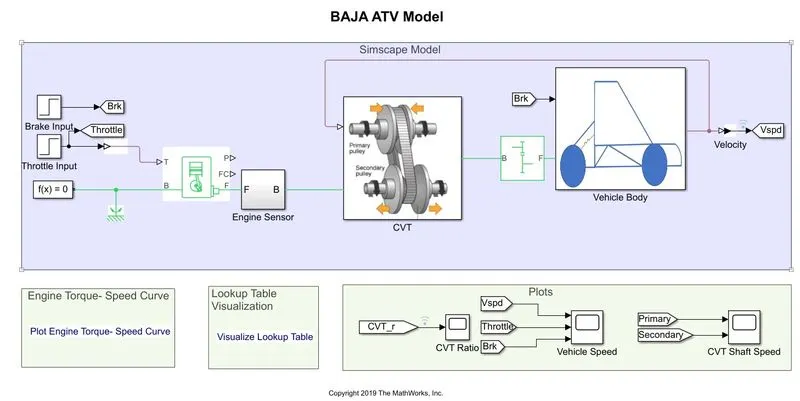
~The Blocks we have used are :--
- Break Input
- Throttle Input
- Generic Engine
- Engine Sensor
- Simple Gear
- Solver configuration
- Mechanical reference
- Constants(2)
- CVT Blockset (CVT Subsystem)
- Vehicle Body
- Scope(2)
- Engine torque Speed curve
- Look Up table curve
~Now we will Gothrough the above Mentioned Blocks:--
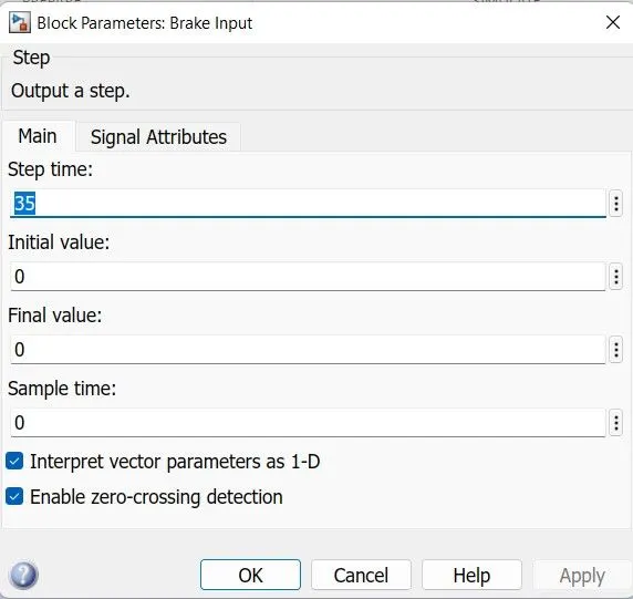
- Break Input :--
in break input we have added it through step blocks and it is shown in the below figure
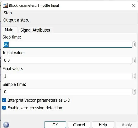
- Throttle Input :--
Throttle input is we have added it through step blocks and it is shown in the below figure
- Generic Engine:--
Represents a system-level model of spark-ignition and diesel engines suitable for use at initial stages of modeling when only the basic parameters are available. Optional idle speed and red line controllers are included.
The throttle input signal T lies between zero and one and specifies the torque demanded from the engine as a fraction of the maximum possible torque. If the engine speed falls below the Stall speed, the engine torque is blended to zero. If the engine speed exceeds the Maximum speed, the simulation stops and issues an error message.
Connections F and B are mechanical rotational conserving ports associated with the engine crankshaft and engine block, respectively. Connections P and FC are physical signal output ports through which engine power and fuel consumption rate are reported.
- Engine Sensor:--
we have created the engine sensor subsytem inside this subsystem the RPM Sensor Block used and that is connected to the Throttel Gauge
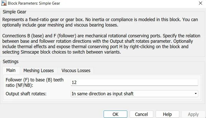
- Simple Gear:--
Represents a fixed-ratio gear or gear box. No inertia or compliance is modeled in this block. You can optionally include gear meshing and viscous bearing losses.Connections B (base) and F (follower) are mechanical rotational conserving ports. Specify the relation between base and follower rotation directions with the Output shaft rotates parameter. Optionally include thermal effects and expose thermal conserving port H by right-clicking on the block and selecting Simscape block choices to switch between variants. and here we have used 12 gears
- Solver configuration:--
Defines solver settings to use for simulation.
- Mechanical reference:--
This block represents a mechanical rotational reference point, that is, a frame or a ground. Use it to connect mechanical rotational ports that are rigidly affixed to the frame (ground).
- Constants(2):--
Output the constant specified by the 'Constant value' parameter. If 'Constant value' is a vector and 'Interpret vector parameters as 1-D' is on, treat the constant value as a 1-D array. Otherwise, output a matrix with the same dimensions as the constant value.
- CVT Blockset (CVT Subsystem):--
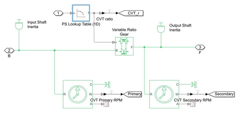
CVT is nothing but Continious Variable Transmission,A continuously variable transmission (CVT) is an automatic trasmission that can change seamlessly through a continuous range of gear ratio This contrasts with other transmissions that provide a limited number of gear ratios in fixed steps. The flexibility of a CVT with suitable control may allow the engine to operate at a constant RPM while the vehicle moves at varying speeds. and when the variator of the primary pulley is moved outwards then the variator of the secondary pulley moves inwards then it leads to the speed reduction, and similarlly when the variator of the primary pulley moves inwards and the variator of the secondar pulley moves outwards then this leads to over drive and this had been shown in the below figure and even the subsystem is also shown below
~Subsystem for the Continious Variable Transmission(CVT):--
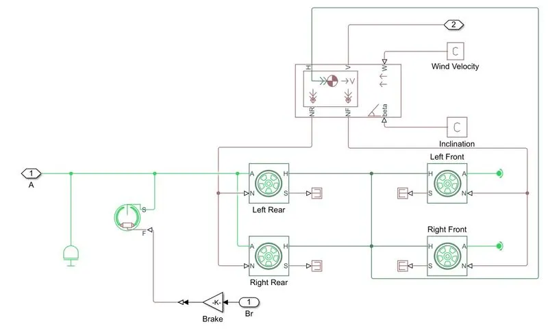
- Vehicle Body:--
The vehicle body could be the main supporting structure or its particular element. The Vehicle Body of a modern car consists of an engine section, saloon, trunk. The vehicle body is the main supporting structure of a vehicle, to which all other components are attached.basically here we have a subsystem called vehicle body and that subsystem is as shown below
- Scope(2):--
Scope is used to show the output results
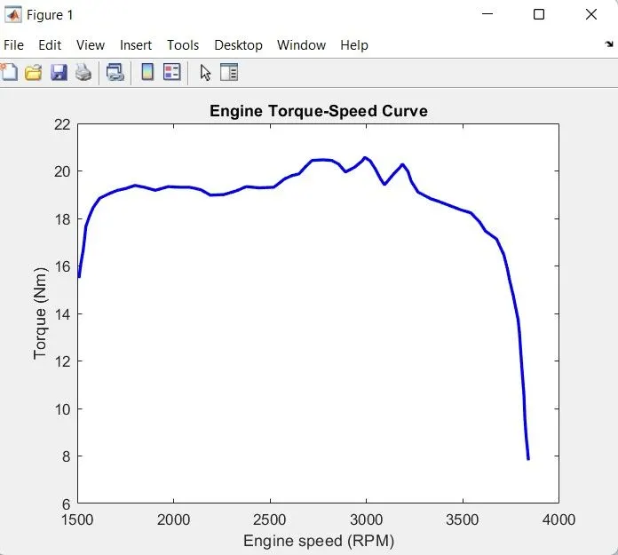
- Engine torque Speed curve :--
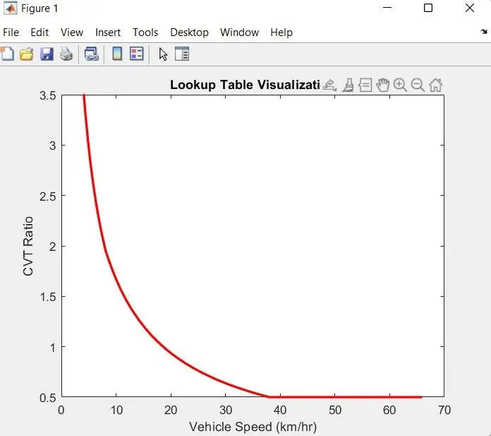
- Look up table curve :--
~Now let us run the model and see the Output:--
~Now lets see what is the happening inside the CVT subsystem:--
Here in the above figure shows the inertia of input and output shaft is reperesting the primary and secondary pulley and to specify the ratio we have used the gear ratio block and the two motion sensors are used to show the CVT primary RPM and CVT secondaryRPM
~Simple Gear ratio :--
To reduce the speed of the engine we have used the simple gear ratio and the gear ratio is 10 and it is shown in the below block and With the current vehicle parameters, the model is designed with gear ratio =12.For different vehicle parameters, you will need to tune the gear ratio.
~Now we will look into the vehicle body subsystem:--
Basically the vehicle body consist of vehicle body where we can specify mass wheels pe axil and etc and the tyre models
~Now lets run and see the output after Changing the Throttle,Break and CVT inputs
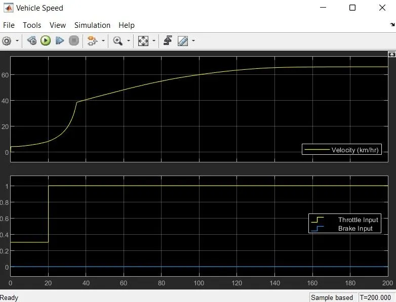
the above figure shows the braek,throttle and velocity outputs and as throttle is increased the velocity is also increased
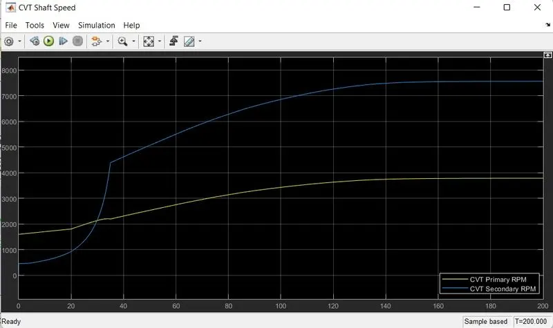
The above output shows the Primary and secondary CVT RPM curve the yellow line represents the primaryRPM and the blue line shows the secondary RPM
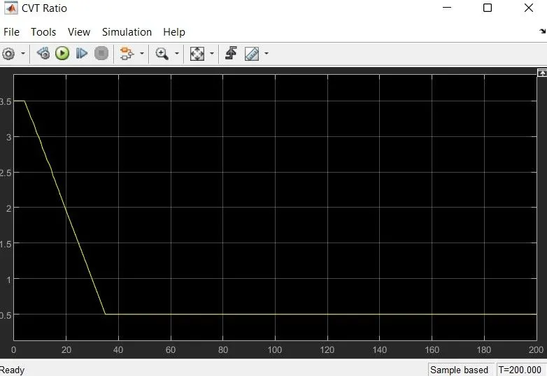
the above figure shows the CVT ratio output
~Drive link for the model:--
https://drive.google.com/drive/folders/1N8Gzb5qKjuU3wDtffMihGRWF4BUiFp2B?usp=sharing
~REFERENCES:--
- Modeling of a Continuously Variable Transmission (CVT) BAJA All-Terrain Vehicle (ATV) Video - MATLAB & Simulink (mathworks.com)
- Frictional brake with two pivoted shoes diametrically positioned about a rotating drum with triggered faulting - MATLAB - MathWorks India
- Tire with longitudinal behavior given by Magic Formula coefficients - MATLAB - MathWorks India
- Approximate one-dimensional function using specified lookup method - MATLAB - MathWorks India
- Internal combustion engine with throttle and rotational inertia and time lag - MATLAB - MathWorks India
~RESULT:--
Thus we have successfully analysed 4 different models of BAJA ATV WITH CVT and recorded the outputs: - (Vehicle velocity & CVT shaft rpm) with respect to variations in input throttle and brake.