Project
EV LIVE BATCH:-21
Ans:- Final Project
Aim:-
To prepare a technical report for Bajaj All Terrain Vehicle (ATV) model by without using Look up table & by using a Look up table.
Objective:-
To carry out a system-level simulation of an all-terrain vehicle,Prepare a technical report explaining the model properties & comments on the results.
All-Terrain Vehicle:-
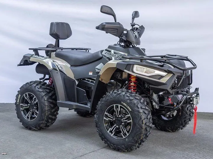
- An all-terrain vehicle (ATV) is defined as a motorized off-highway vehicle designed to travel on four low-pressure or non-pneumatic tires, having a seat designed to be straddled by the operator and handlebars for steering control.
- a small motor vehicle with three or four wheels that is designed for use on various types of terrain called as ATV.
- after downloading the file given in the question,we can see that there are two model folders in which Model-1 consist of two simulink model & Model-2 consist of 2 major simulink models.

- we have to analyse both model folders containg different simulink models.
1. # 1_Models folder:-
when we open this 1_Models folder then we can see that there are two simulink models such as:
- cvtModel.slx
- cvtModel_dashboard.slx
(A) Case 1:-
Simulink model of BAJA ATV with CVT:-
when we open the cvtModel.slx model then we can see a model as follows:-
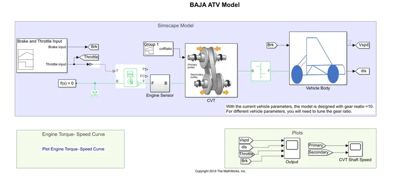
- This model consist of some major components such as Signal builder block, CVT block,Generic engine block, vehicle body & some other components.
- here we have give the Throttle (accelerator) input & brake input in the signal builder block as follows:-
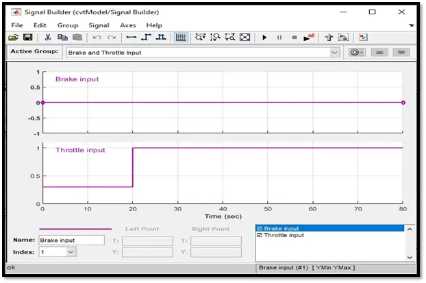
we can see from the grapgh as the brake input is always 0 for entire 80 sec & the throttle input varries such as from 0sec to 20sec, throttle value is 0.3 then from 30sec to 80sec, throttle value is 1.
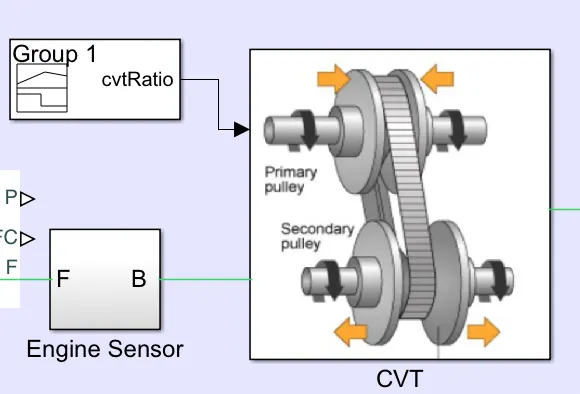
- when we open the CVT block (contineously variable transmission drive) which is the main component of this model, then we can see that
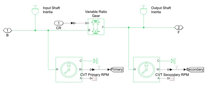
- here we can see that input to the CVT block is provided by cvtRatio signal builder block such as:-
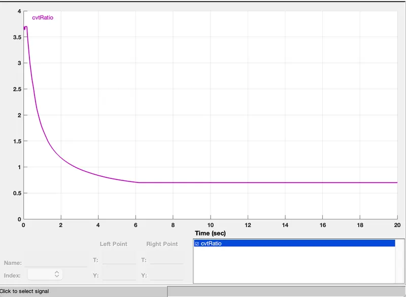
- we have given variable gear ratio to the CVT block through Variable Ratio Gear block inside CVT block.by giving the variable gear ratio we can see the difference between primary & secondary shaft angular velocities.
- Vehicle Body:-
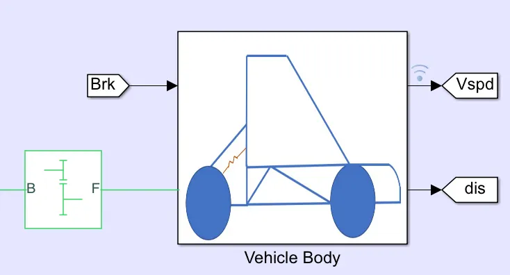
Here we can see that, inputs to the vehicle body are brake input from the signal builder block & a Simple gear block coming from the CVT block. outputs from the vehicle body are Vehicle speed (Vspd) & displacement covered by the vehicle.
when we again open the vehicle body block then we will see that,
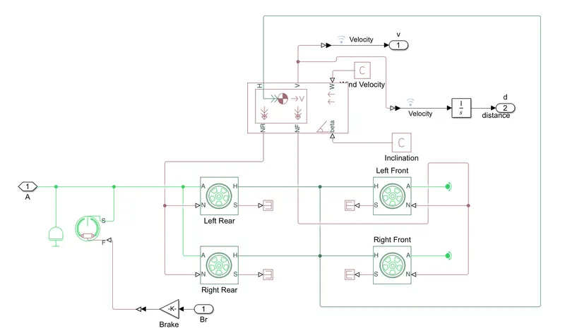
Here we can see that there are 4 wheels such as 2 left wheels & 2 right wheels. i/p are brake & simple gear, outputs are velocity & distance.
Outputs for Case 1:-
there are two output scope to see the results of Case 1
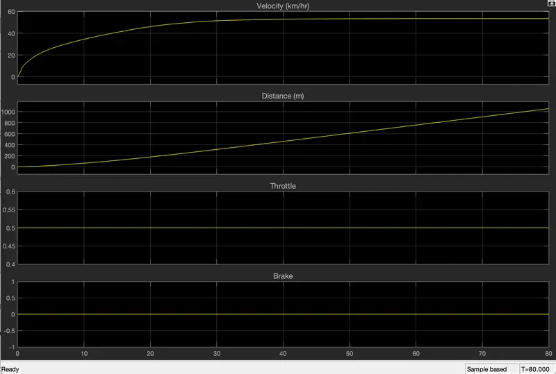
from this graph, we can analyse that velocity of the vehicle reaches it's maximum value of arround 55 km/hr after 30 sec then it becomes constant at it's maximum velocity as there is no brake input so here brake does not affect the vehicle velocity. & as the vehicle is moving in a constant speed so it covers a distance of 1000 meter after 80sec.
in this case whave only considered abbput the throttle input & no brake input. so here brake has no effect on the velocity of the vehicle.
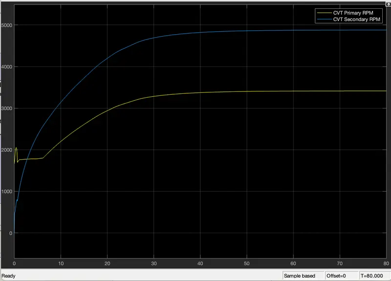
this graph shows Primary angular speed & Secondary angular speed of input shafts & output shafts of variable gear transmission system. these graphs are differ according to the gear ratio.
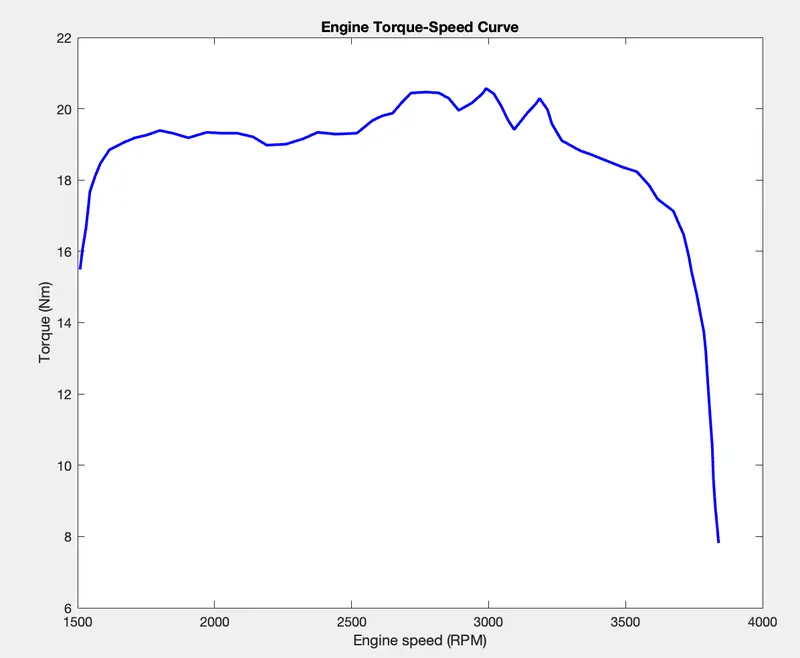
This is a plot between Engine speed of the vehicle in RPM & Torque of the engine in Nm. Initially, when Torque is 15.49 Nm then Speed of the engine is 1509 RPM. then at engine speed of 2991 RPM the Torque of the engine is maximum of 20.57 Nm means then the acceleration of the vehicle wil decrease. but at Torque of 7.817 Nm the speed of the Engine reaches it's maximum value of 3840 RPM.
(B) Case 2:-
Simulink Model of BAJA ATV with CVT dashboard:-
when we open cvtModel_dashboard.slx then we can see a model as follows:-
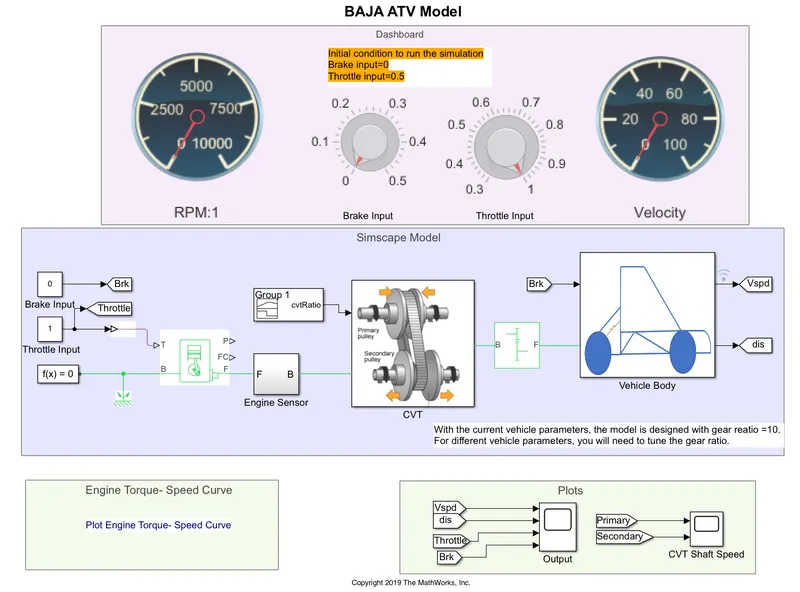
- Here we don't use signal builder to give the input signal to the model. here two Knobs are used to control the Throttle input & brake input instaed of a signal builder.
- A real time user can control or change the values of Throttle input & brake input by the help of Knobs.
- here some initial conditions are given to keep the knobs before simulation such that Brake input = 0 & Throttle Input = 0.5
- then we we simulate the model & we have to contineously change the values of Throttle input & brake input to see the effect of these inputs in the Output scope.
Outputs for Case 2:-
- Vehicle Velocity:-
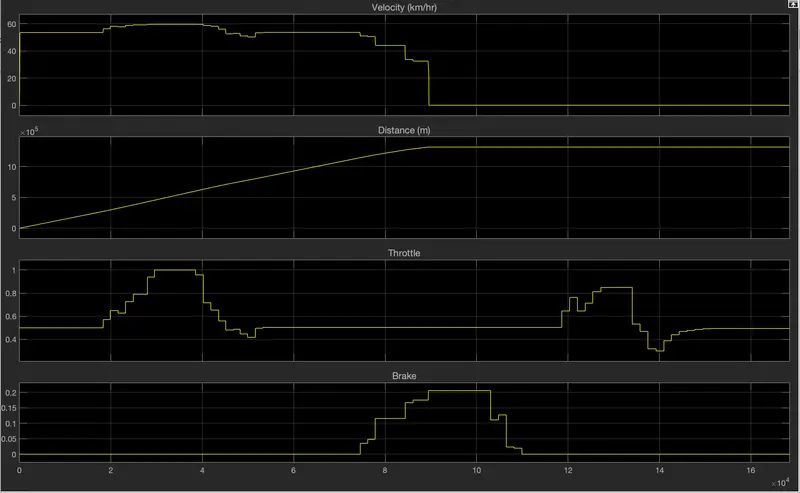
from this graph, we can analyse that intially when the throttle is 0.5 & brake input is 0 then the velocity of the vehicle is 55 kmph but when we increse the throttle input then the velocity increses & vice-versa. but by invresing the brake input, our vehicle velocity decreases & vice-versa.
but when we set the brake input as 0.2 then the vehicle velocity is 0 then we can see that once the vehicle velocity reaches at 0 then whatever the change in the throttle & brake input doesn't effect on the vehicle velocity.i.e:- the vehicle velocity remains 0 kmph further.
we can see that, when the vehicle is moving with some velocity then the displacement line increases & when the velicle velocity reaches at 0 then the displacement line will be constant means there is no movement of the vehicle.
- CVT shaft RPM:-
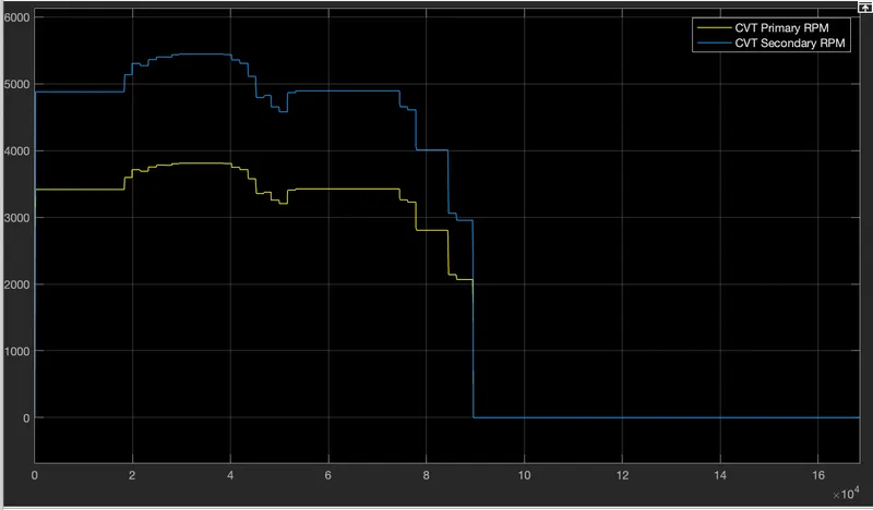
Here we can see that both Primary & secondary shart RPM curves are simillar but their values differs due to the variable gear ratio.
2. 2_Models_LookupTable folder:-
(A) Case 1:-
Simulink Model For BAJA ATV with CVT using Lookup Table:-
- Model:-
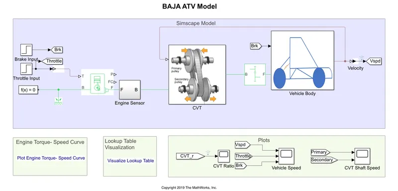
if we compare this model with the case 1 model of the previous folder, then we can see that we have used step signal blocks instead of signal builder block to representing the Throttle input & Brake input. there is a feedback connection from the output (Vehicle speed) of vehicle body to the input of the CVT block.
- CVT block:-
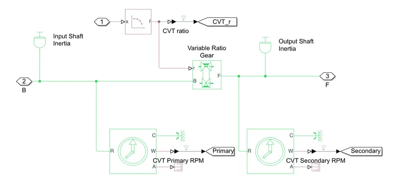
here we can see that we have used a Lookup table instead of a signal builder block to representing the CVTratio (variable gear ratio)
- Vehicle Body:-
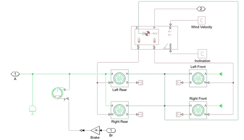
here we can see that there is no change in the vehicle body model which means that it is same as the previous models.
- CVT ratio:-
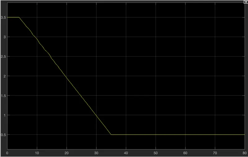
this CVT ratio graph is different from the previous model CVT ratio graph.
Outputs for Case 1:-
- Vehicle speed:-
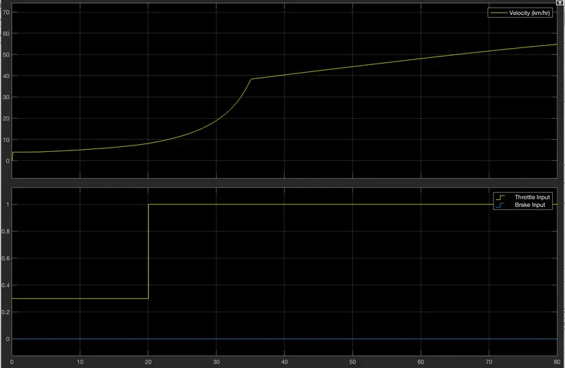
here we can see that, at the initial condition when the throttle value is 0.3 for 20 sec then the speed of the vehicle increases slowly. bit after 20sec, when the throttle value is 1 (Maximum) then the velocity increases upto 40 kmph in 15 sec then the velocity increases slowly as the throttle is 1. here brake doesn't effect on the vehicle velocity as brake is input is 0 through out the simulation.
- CVT shaft RPM:-
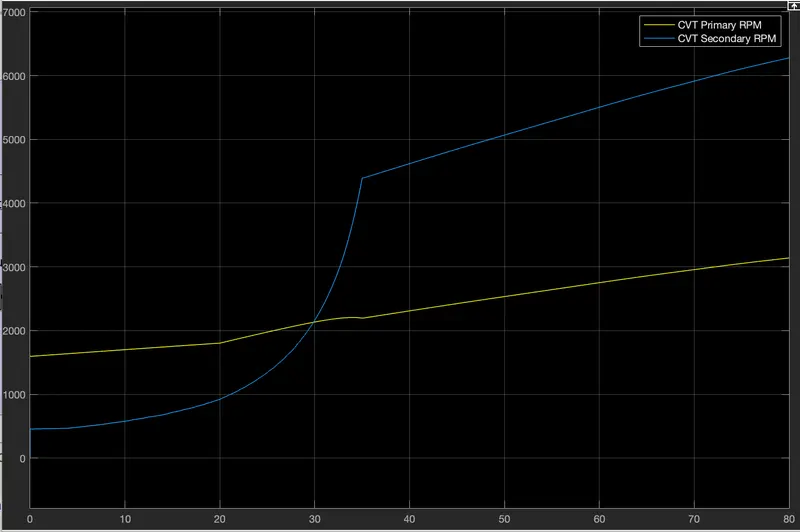
as we discussed before, these two RPM graphs differ with respect to the gear ratio.
(B) Case 2:-
Simulink Model for BAJA ATV with CVT dashboard using Lookup Table:-
- Model:-
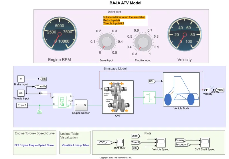
the big difference between this model & the case 2 model of the 1st folder is that here we have used a feedback signal comming from the output (Vspd) of the vehicle body to thr input of the CVT block. here we have used Knobs to control the throttle input & brake input of the model.
here it is given some initial conditions for throttle input & brake input such as Throttle input = 0.3 & Brake input = 0
after keeping this initial conditions we can go for the simulation.
- CVT block:-
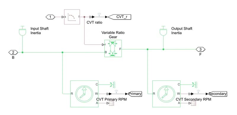
Here we can see that, we have used a Lookup table instead of a singal builder block containing cvtRatio signal.
- Vehicle Body:-
We can see that there is no change in modelling the vehicle body.
Outputs for Case 2:-
- Vehicle speed:-
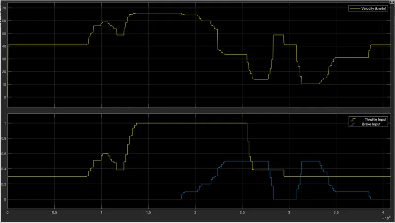
From the above graph we can analyse that, at the intial condition when the throttle input is 0.3 & brake input is 0 then our vehicle moves at around 41kmph. then when we increase the Throttle input value then the velocity increases & reaches at 65 kmph which is Maximum velocity for maximum throttle value of 1 & if we decreses the throttle value then velocity decreases.
when we increases brake input value then velocity decreases & vice-versa. the minimum velocity of the vehicle is 10 kmph at throttle value of 0.3 & brake input 0.5(Maximum).
we can concluded that the velocity of the vehicle is directly propertional to Throttle input & inversely propertional to the Brake input.
here we obserbed that vechile velocity doesn't fall to 0 kmph because we have connected from the output to the input.
- CVT shaft Speed:-
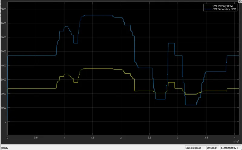
As we have discussed before, the Primary RPM & Secondary RPM differes with respect to Gear ratio.
Conclusion:-
- We can say that Models present in the 2nd folder are real-time Model.
- vehicle of the velocity may comes to 0 in the 1st folder simulink model but Vehicle velocity doesn't comes to 0 in the 2nd folder simulink model.
- We can say that Simulink models used in 1st folder are open loop system i.e:- there is no feedback connection between the output to the input but the simulink model used in 2nd folder are closed loop system which give more efficiency then the 1st one.
- we have discussed 4 models for All-Terrian Vehicle (ATV) sucessfully.