Project
Aim:
To prepare a technical report explaining the model properties of the BAJA All-Terrain Vehicle in different conditions.
All-Terrain Vehicle:
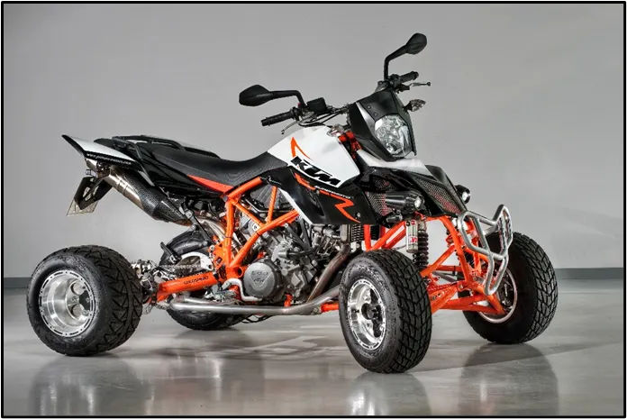
An All-Terrain Vehicle (ATV), also known as a light utility vehicle (LUV), a quad bike, or simply a quad. It is a vehicle that travels on low-pressure tires, with a seat that is straddled by the operator, along with handlebars for steering control. As the name implies, it is designed to handle a wider variety of terrain than most other vehicles.
BAJA ATV Model
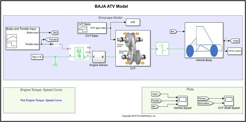
The model consists of the following components:
a] Signal Builder
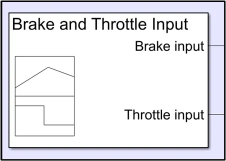
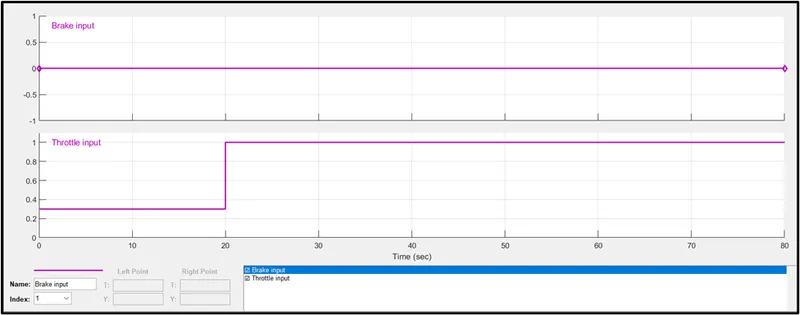
The signal builder is used to give the brake and the throttle inputs for the model. The input can be changed as per user convenience.
b] Generic Engine
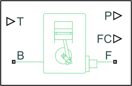
It represents a system-level model of spark-ignition and diesel engines suitable for use at the initial stages of modeling when only the basic parameters are available. Optional idle speed and red line controllers are included. The throttle input signal T lies between zero and one and specifies the torque demanded from the engine as a fraction of the maximum possible torque. If the engine speed falls below the Stall speed, the engine torque is blended to zero. If the engine speed exceeds the maximum speed, the simulation stops and issues an error message. Connections F and B are mechanical rotational conserving ports associated with the engine crankshaft and engine block, respectively. Connections P and FC are physical signal output ports through which engine power and fuel consumption rate are reported.
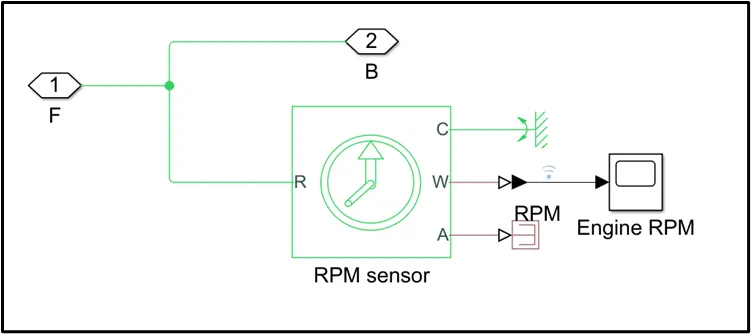
c] Engine Sensor
This block measures angular velocity or angle in a mechanical rotational network. The sensor is ideal since it does not account for inertia, friction, delays, energy consumption, and so on.
The physical signal ports W and A report the angular velocity and angle, respectively, of port R relative to port C. The measured angular velocity is positive when the angular velocity at port R is greater than the angular velocity at port C.
d] CVT(Continuous Variable Transmission )
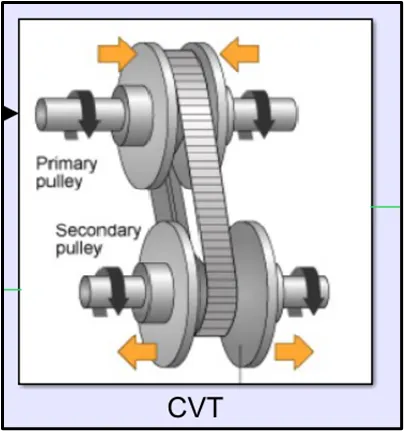
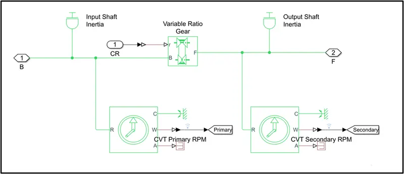
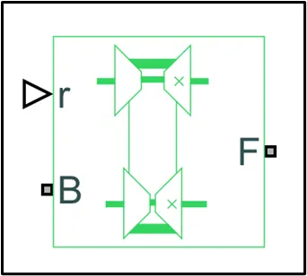
CVT consists of a Variable Ratio Gear which represents a variable ratio gearbox such as implemented by mechanical belt CVT, electric, or hydraulic transmissions. The physical signal input r defines the ratio of input to output angular shaft velocities. Connections B (base) and F (follower) are mechanical rotational conserving ports.
Variable ratio gear
e] Simple Gear
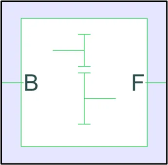
Represents a fixed-ratio gear or gear box. No inertia or compliance is modeled in this block. You can optionally include gear meshing and viscous bearing losses. Connections B (base) and F (follower) are mechanical rotational conserving ports. Specify the relation between base and follower rotation directions with the Output shaft rotates parameter. Optionally include thermal effects and expose thermal conserving port H by setting Friction model to a temperature-dependent setting.
f] Vehicle Body
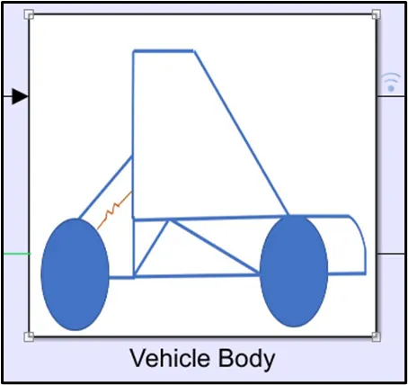
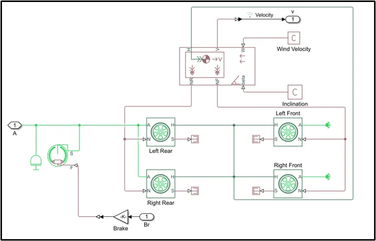
Represents a two-axle vehicle body in longitudinal motion. The block accounts for body mass, aerodynamic drag, road incline, and weight distribution between axles due to acceleration and road profile. The vehicle can have the same or a different number of wheels on each axle. Optionally include pitch and suspension dynamics or additional variable mass and inertia. The vehicle does not move vertically relative to the ground.
Connection H is the mechanical translational conserving port associated with the horizontal motion of the vehicle body. The resulting traction motion developed by tires should be connected to this port. Connections V, NF, and NR are physical signal output ports for vehicle velocity and front and rear normal wheel forces, respectively. Wheel forces are considered positive if acting downwards. Connections W and beta are physical signal input ports corresponding to headwind speed and road inclination angle, respectively. If variable mass is modeled, the physical signal input ports CG and M are exposed. CG accepts a two-element vector representing the x and y distance offsets from vehicle CG to additional load mass CG. M represents the additional mass. If both variable mass and pitch dynamics are included, the physical signal port J accepts the inertia of the additional mass about its own CG.
Input signal
Throttle and brake input
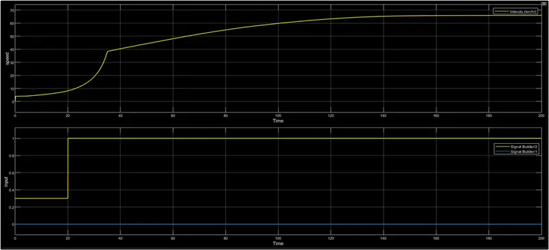
Using the signal builder the input is given to the generic engine. The inputs are brake and throttle input as can be seen below. The graph is plotted as Input v/s Time(sec). So the brake input is 0. Whereas the throttle input is 0.3 for the first 20 sec and after 20 sec the input is 1.
CVT ratio
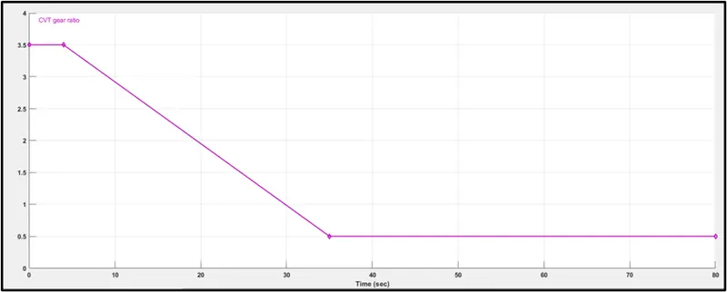
The below plot of the graph shows the CVT gear ratio input. As can be seen for the first 4 sec the gear ratio is 3.5, after 4 sec the gear ratio is steadily decreased to 0.5 at 35 sec. After 35 sec the gear ratio is again constant at 0.5.
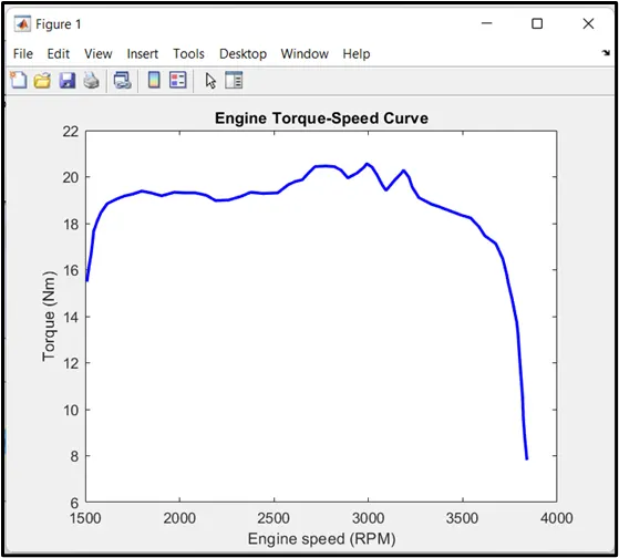
Engine Torque-Speed Curve
Output
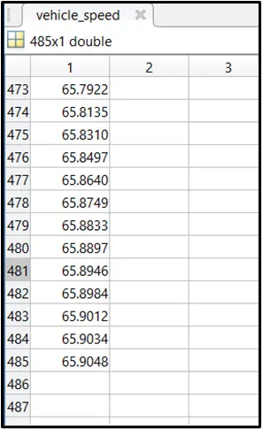
The graph of speed v/s time shows the velocity of the vehicle. The maximum velocity attained is 65.9048 km/hr.
Output
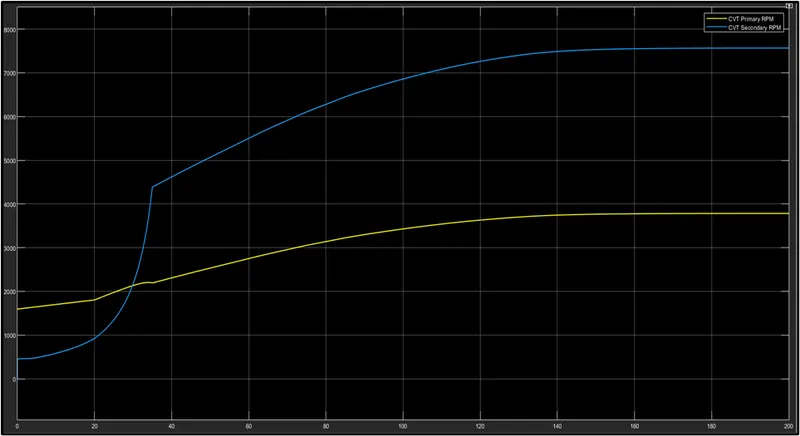
The below graph shows the plot of CVT primary and secondary speed. We get the output based on the CVT ratio. The secondary shaft speed is similar to the velocity since it is connected to the rear wheel. The maximum rpm of the secondary pulley is 7567 rpm and the maximum speed of the primary pulley is 3784 rpm.
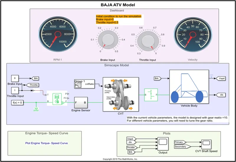
Model of BAJA ATV with CVT using Dashboard
This model has a dashboard interface that has knobs to give or control the inputs to the model.
The Throttle and the Brake input are controlled using the knobs.
Output
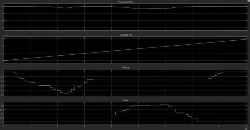
It can be seen that there is a drastic increase in the velocity from 0 to 50 km/hr when the throttle input is 1 and the brake input is 0. When the throttle is varied and no brake input is applied the velocity also varies. Also when the throttle input is made constant at 0.85 as shown in the figure, and brake input is applied then there is a decrease in velocity. This shows the direct relation of vehicle velocity with respect to the throttle input and the brake input. The distance keeps on increasing with respect to time since the throttle is not set to 0 and brake input is not maximum.
CVT Shaft Speed
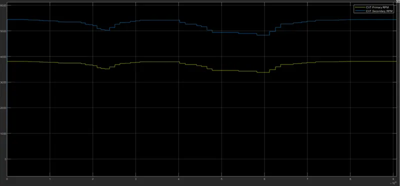
The Above figure shows variation in the CVT primary and the secondary rpm with respect to the input given.
Conclusion.
The purpose of this project was to study the BAJA ATV Model and analyze the output of the vehicle with respect to the inputs applied. We have seen the ATV model using the CVT gear ratio only, CVT and the dashboard. The model also can be analyzed using the lookup table. The output are similar when compared to CVT only. Hence it can be concluded that we have successfully analyzed the output of BAJA ATV Model varying the different parameters using different interfaces and inputs.