Project 1 (Mini Project on Vehicle Direction Detection
MBD live batch 7
Mini Project on Vehicle Direction Determination.
Aim:- 1. To develop a Vehicle Direction Detection model in Simulink.
2. To tag the model subsystems with the requirement document.
3. Creating a Simulink Data Dictionary for the model.
4. To generate an S function for the subsystems and to do the model advisory checks.
General Overview:
Identifying the direction of the vehicle is one of the important & diverse features in Autonomous driving & Advanced Driver Assistance Features. This particular sub-feature of identifying the direction of vehicle is basically identifying the direction the vehicle is taking based on the camera input.
Camera reads the road signs & stores into its memory with unique values for left turn, right turn & straight drive. Depending on the direction it is taking, final indication is given to the driver – as an indication if he is driving in the recommended direction or not.
Vehicle Direction Determination can also be coupled along - side features like GPS systems to identify whether the vehicle is reaching its destination in an optimized manner. This sub feature can also be used along with Lane Detection, Highway Warning, Ramp Entry / Exit in Wrong Way Detection etc.
Steps:-
1. Model complaint changes
Step 1- Configuration Settings
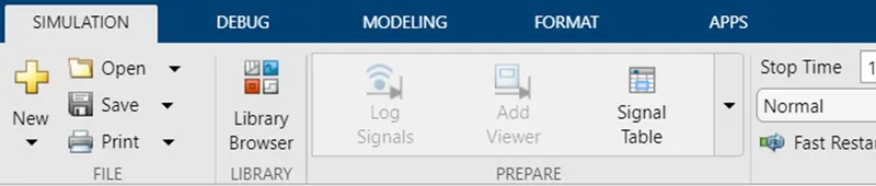
Go to the modeling tab.
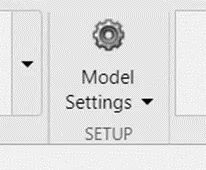
Under the modeling tab click on the Model Settings.
A dialogue box will open as shown below.
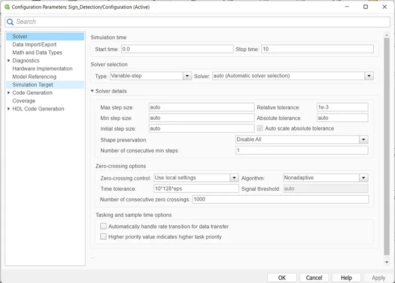
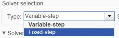
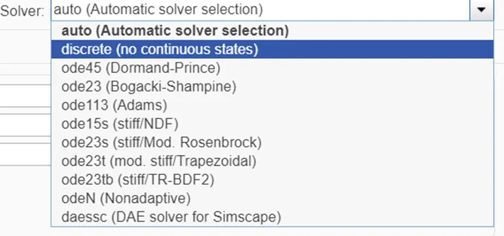
Change the Variable-step to Fixed-step.
Change the solver as discrete (no continuous states)
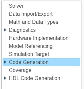
Click on code generation.
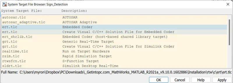
Click on browse.

Change to Embedded Coder.
2. Creation of model
For creating the model we have divided the logic into 2 subsystems as can be seen below.
The inputs given are for the system that is the steering wheel yaw degree and the camera input road sign.
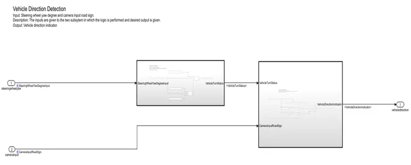
As per requirement 1 , the following logic is applied.
Requirement - 1:
- Steering wheel input as yaw rate (Signal name: SteeringWheel_YawDegreeInput) is the input for this system.
- This is compared against 3 angular values, one each for left turn, right turn & straight drive (Calibration Values: Right_Turn_AngularLimit, Left_Turn_AngularLimit, Straight_Drive_Steering_Angle) to say which specific direction the steering wheel is turning towards.
- Use switch blocks to compare & develop this requirement. Keep this requirement in a subsystem & output of this requirement is a local signal (Signal Name: Vehicle_Turn_Status).
We have taken the steering wheel yaw degree as the input . the input is given to a switch block. the two switch blocks are given the thresholds as >=0 and >=30. If the input value is more than 0 or equal to 0 , the value stored in the straight drive steering angle is given as output, else if the input is more than 0 then the value in the left turn angular limit is given out.
This output is fed to the second switch block as input. If the input is greater or equal to 30 the right turn angular limit value is given as output else the output is given from the first switch block.
The output given out gives the vehicle turn status of the vehicle and is treated as local varable.
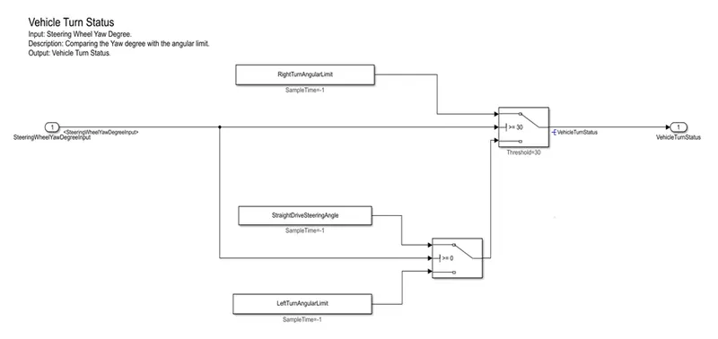
The logic for the second subsystem as per requirement 2 is shown below.
Requirement – 2:
- Keep this requirement as a separate subsystem. Inputs to this requirement are local signal from requirement 1 (Signal Name: Vehicle_Turn_Status) & an input signal from camera (Signal Name: CameraInput_RoadSign), which confirms the occurrence of a road sign.
- Signal Vehicle_Turn_Status is compared against calibration values (Calibration Values: RightTurn_RoadSign, LeftTurn_RoadSign, Straight_RoadSign), if each of them is found equal, then each of the three corresponding output is compared against the camera input signal,
- Using a logical operator block, only one among them is finally given as output signal (Signal Name: Vehicle_Direction_Indicator).
For this logic we are taking both the inputs. The first input is the vehicle turn status from the first subsystem. It is given to the relational operators , and is compared with the RightTurn_RoadSign, LeftTurn_RoadSign and Straight_RoadSign . after comparing it is given to the AND operator , where the AND operation will be performed between the above input and the camera input road sign. The output is given to MUX and given to a signal conversion block. Either of the 3 signals are given as the output. This output is the Vehicle_Direction_Indicator.
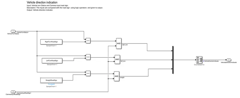
3. Creating SLDD
|
Signal / Calibration Name |
Signal Type |
Data Type |
Dimension |
Min |
Max |
Initial Value |
Units |
||||||
|
SteeringWheel_YawDegreeInput |
Input |
Int16 |
1 |
-180 |
180 |
- |
Deg |
||||||
|
CameraInput_RoadSign |
Input |
Boolean |
1 |
0 |
1 |
- |
- |
||||||
|
Vehicle_Turn_Status |
Local |
Int16 |
1 |
-180 |
180 |
- |
Deg |
||||||
|
Right_Turn_AngularLimit |
Calibration |
Int16 |
[1 1] |
-180 |
180 |
30 |
Deg |
||||||
|
Left_Turn_AngularLimit |
Calibration |
Int16 |
[1 1] |
-180 |
180 |
-120 |
Deg |
||||||
|
Straight_Drive_Steering_Angle |
Calibration |
Int16 |
[1 1] |
-180 |
180 |
0 |
Deg |
||||||
|
RightTurn_RoadSign |
Calibration |
Int16 |
[1 1] |
-180 |
180 |
30 |
|||||||
|
LeftTurn_RoadSign |
Calibration |
Int16 |
[1 1] |
-180 |
180 |
-120 |
|||||||
|
Straight_RoadSign |
Calibration |
Int16 |
[1 1] |
-180 |
180 |
0 |
|||||||
|
Vehicle_Direction_Indicator |
Output |
Boolean |
1 |
0 |
1 |
- |
- |
||||||
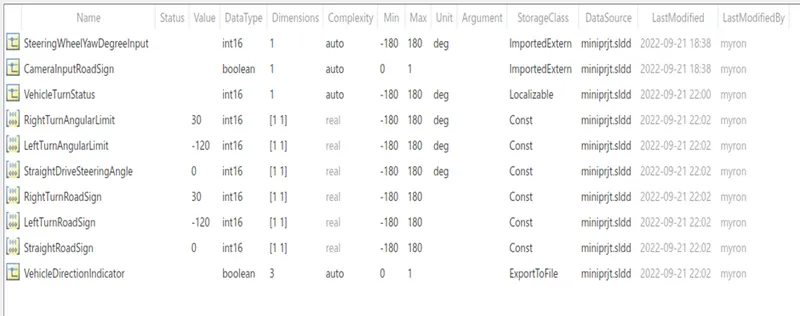
As per the required inputs, outputs, and parameters ,we have created the following Simulink Data Dictionary.
4. Generating S Function
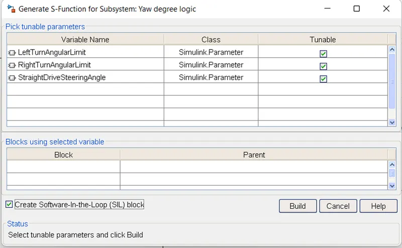
To create the S function, roght click on the subsystem and click on C/C++ code , click on generate S Function.
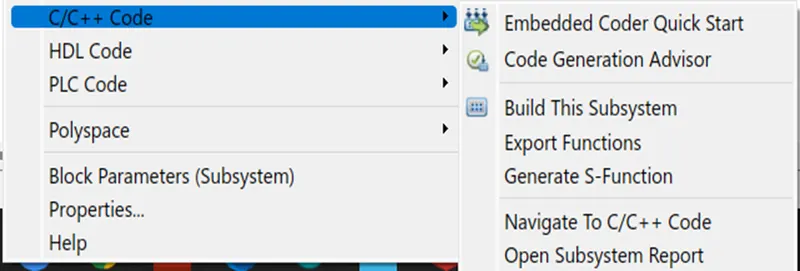
A dialogue box will open , tick the Create Software In Loop (SIL) block. And click build.
5. Model advisory check
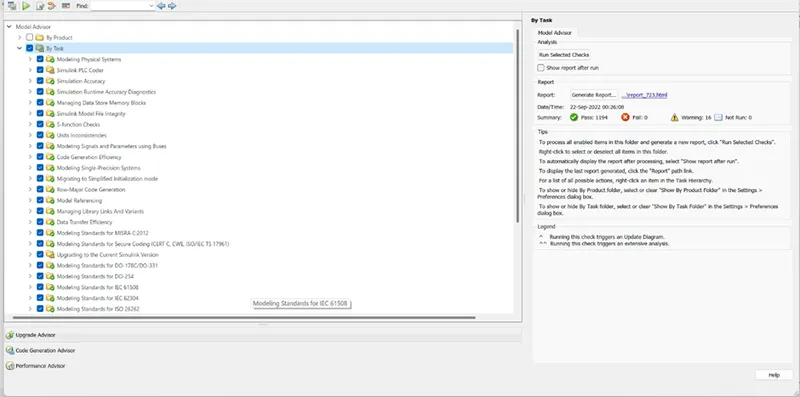
The model advisory check is performed on the model and all the failed and warnings conditions are corrected. The report is attached as the .html file.
6. Requirement tagging
The requirement tagging is carried out for this project. the requirements are listed in the MS Word and are linked to both the subsytems. The requirements are attached as .docx file.
Results:-
We have successfully created the model foe the Vehicle Direction Detection. The model is checked for any errors or warnings using the Model Advisory checks. Also we have successfully created an SLDD for the model. We have also done the Code generation for the model.