Project
Aim :- Carry out a system-level simulation of an all-terrain vehicle.
ATV Basic Information :-
An all-terrain vehicle (ATV) is defined as a motorized off-highway vehicle designed to travel on four low-pressure or non-pneumatic tires, having a seat designed to be straddled by the operator and handlebars for steering control. ATVs are subdivided into two types as designated by the manufacturer. Type I ATVs are intended by the manufacturer for use by a single operator and no passenger. Type II ATVs are intended by the manufacturer for use by an operator and a passenger, and are equipped with a designated seating position behind the operator. Similarly, riders must also consider the various ATV sizes.
ATVs are not “one size fits all.” The ATV industry recommends all riders operate an ATV intended for their age. Youth model ATVs are designed for smaller hands and feet, and travel at slower speeds appropriate for their age.
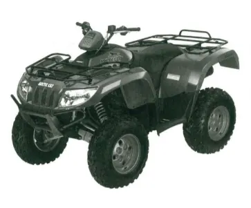
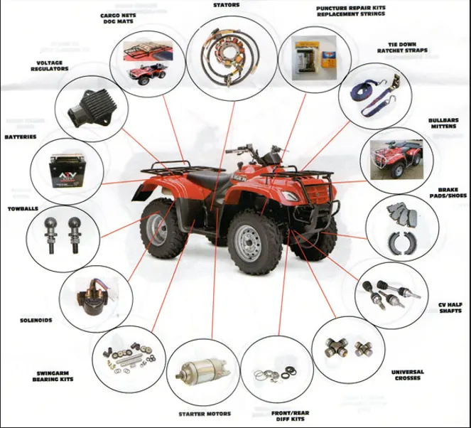
ATV Basic Parts :-
CVT Basics :-
A CVT or Continuously Variable Transmission is an automatic, single speed, and gearless transmission that can shift through an infinite number of gear ratios.
A continuously variable transmission (CVT) is a transmission that operates on an ingenious pulley system that automatically varies the transmission ratio, allowing an infinite variability between highest and lowest gears with no discrete steps or shifts. CVTs provide more useable power, better fuel economy and a smoother driving experience than traditional transmissions that use gearboxes with fixed numbers of gear sets.
A continuously variable transmission system is a type of automatic transmission in which an arrangement of pulleys and belts made it possible for a drive to achieve n-number of continuous gear ratios within a range (depends on the design).
A continuously variable transmission in a vehicle senses the accelerator input with engine load and get shifted to the desired speed or torque gear ratio automatically, in other words we can say that a cvt transmission is one of the simplest types of automatic transmission that provides continuous uninterrupted power within a specified range of speed and torque ratios.
COMPONENTS OF CVT:
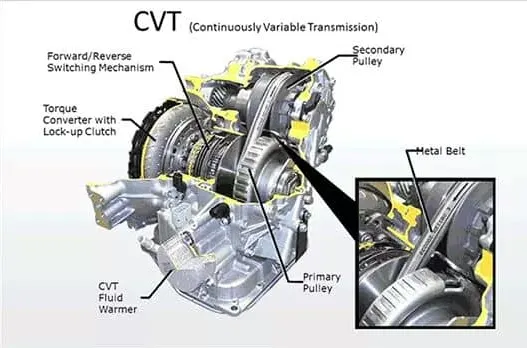
1. Clutches
I. Primary clutch
The primary clutch is an advanced form of centrifugal clutch and is typically mounted to the output end of the engine crankshaft. The clutch has two sheave faces; one that is laterally fixed (stationary sheave), and one that can move in and out to engage the belt (moveable sheave). In most systems, at idle the sheave surfaces are spread at their widest spacing, the belt is riding on the post or shaft at the smallest diameter of the clutch, and the belt is not pinched by the sheave faces. This provides a “neutral” position that allows the engine to idle without transmitting power to the wheels.
II. Secondary clutch
The secondary clutch is mounted to the input shaft of the transmission, transaxle, or the like. In modern CVT systems such as those used in recreational vehicles, the secondary clutch has two functions: as a “slave” to the primary clutch and to provide a torque sensing element.
2. Pulleys
In Cvt pulleys play an important role as the conical shape pulleys integrated over input and output shafts are the reason for continuously variable transmission’s continuous n-number of speed and gear ratios, due to the different cross section of these conical pulleys multiple torque and speed ratios are obtained.
Two pair of conical pulleys each for input and output shafts are used in a basic continuously variable transmission that are-
1. Fixed input pulley-
It is a conical pulley mounted over the input shaft (on the right-hand side), this pulley does not move (too and fro) over the shaft but rotates with the input shaft, usually fixed pulley is smaller in size.
2. Fixed output pulley
It same as fixed input pulley but unlike fixed input shaft this shaft is placed on the left-hand side over the output shaft.
3. Feeding input pulley or sheave-
It is the type of conical pulley which is mounted over the input shaft and have inner splines meshed with the shaft splines in such a fashion that it can move (too and fro) as well as rotates with the input shaft. the too and fro moment of this shaft over the input shaft make it possible to shift gear ratios.
4. Feeding output pulley or sheave
Same as moving input pulley but unlike moving input shaft, this shaft is placed on the right-hand side over the output shaft.
3. Shafts
Same as manual transmission type 2 shafts are needed by Cvt transmission to transfer power from engine to the final drive that are-
1. Input shaft-
Same as the manual transmission it is a type of shaft having splines over its cross-section over which input pulleys are mounted, the power source for this input shaft is engine which means continuously variable transmission gets the input from the engine through input shaft.
2. Output shaft-
It is the type of shaft which is kept parallel to the input shaft in a continuously variable transmission, same as input shaft it also has splines over its cross-section and is mounted upon by output pulleys.
Output shaft is responsible to transmit final output power to the final drive of the vehicle.
4. Belt or Chain
The belt in most CVT systems is a heavy duty “V-belt” which is V-shaped in cross section. They are made of rubber components reinforced with Kevlar and other materials to enhance durability.
In a Cvt transmission a v-shaped metallic (rubber in some case) chain or belt is used to transmit power from input pulleys to the output pulleys as this belt or chain is wrapped over both conical input and output pulleys pairs and the V-shape of this belt or chain make it possible to shift gears from high torque to the high speed.
Program Introduction :-
This folder containing four type of program. First program is with defined throttle value with defined CVT ratio data. Second type is same as above but only input of throttle is user defined. In third program, CVT gear ratio not given but it varies after taking feedback from final speed and define ratio from lookup table according to speed with predefined throttle input. And final program is same as third program but only throttle value is use defined.
Main Blocks From all Four Program :-
Generic Engine :
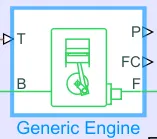
- This block is used to calculate rpm of engine from input of throttle value or required torque value. It will also give fuel consumption and power output.
Signal Builder :
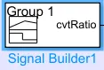
This block is used to build input signal according to user requirement.
Variable ratio transmission :
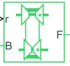
This block is used to conver input speed to output speed according to given gear ratio input.
Ideal Rotational Motion Sensor :
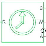
This block is used to sense rpm of output shaft of CVT.
Simple Gear :
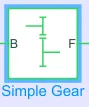
It is used to reduce or increase output with compare to input by using fixed gear ratio.
Double Shoe Brake :
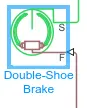
It i used to apply braking over the system.
Tire :

Represents the longitudinal behavior of a highway tire characterized by the tire Magic Formula.
Vehicle Body :
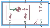
Represents a two-axle vehicle body in longitudinal motion. The block accounts for body mass, aerodynamic drag, road incline, and weight distribution between axles due to acceleration and road profile.
Program 1 :- With predefined Throttle and Brakevalue with CVT ratio input without feedback
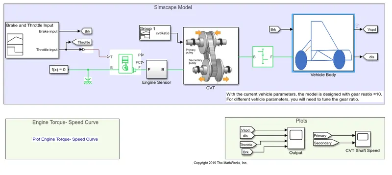
Model Buildup and Working :-
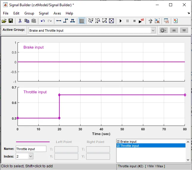
- In this program, first of all throttle and brake iput signal are defined in signal builder block. Whose output is shared with scope for plotting using Goto and From block.
- This signal is given to input port of generic engine. This engine block is connected with tabulated lookup table which is generated from Torque vs Speed real time diagram using grab it function. This engine base is connected to referance and configuration solver for mathematical referance. Output port is connected with engine sensor. Power and Fuel consumption data is not required so those outputs from engine are open.
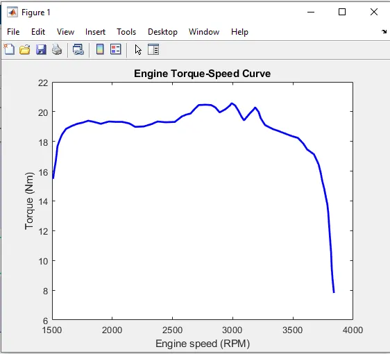
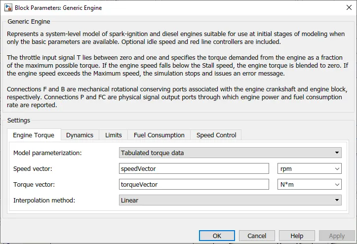
- Now generic engine block is calculating engine output rpm from given throttle and brake input. To measure that rpm engine sensor subsystem is created. In with, ideal rotational motion sensor is connected which take input value from engine output and sense according to referance conncted with it and plot that graph in scope.
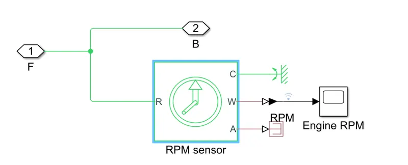
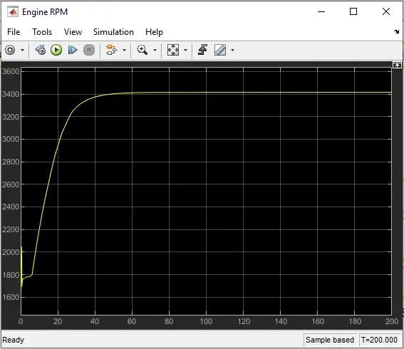
- Now, engine ouput rpm is given to CVT subsystem. In which, variable ratio transmission block is used. Which take input as engine rpm for it's input signal and convert that rpm according to CVT ratio which is also connected to its input port.CVT ratio is given to system using signal builder block. Variable transmission block change output rpm according to CVT ratio and give output. To measure primary and secondary shaft rpm here is ideal rotational sensor is used and output is plot in scope.
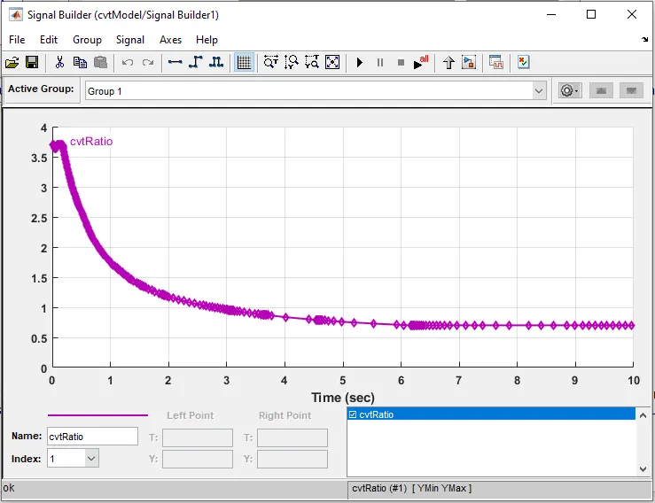
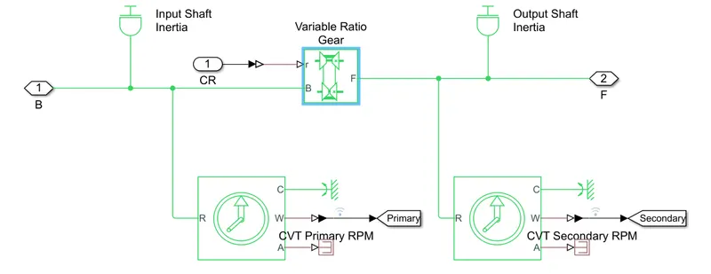
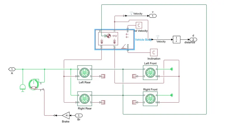
- Now, after converting rpm according to CVT ratio it is transmitted to simple gear block. From reducing rpm it tramsmitted to vehicle body subsystem block. Rpm is connected to the tire block as input.Tire block is connected with vehicle body block and other tires with required referances. As talking about any one tire, it is inputing rpm of engine after CVT conversion and second conserving end is connected with second tire. Third input signal is from vehicle body block and fourth one is attached with referance. From interconnection of first and second tire third and fourth are connected. Also with tyre system brake block is connected with referance port.
- For vehicle body block, it's input port is connected with rpm comes from CVT. This block is computing vehicle CG, force acting on tyre, inclination of road if need and wind speed which ATV is feeling. This block is computing final output of velocity of ATV from which by integrating that velocity we can get distance cover by vehicle. In this system wind speed and inclination angle set to zero value. This tire force is computed by this block and given to the tire block to evaluate output.
- Like this vehicle body block.
Output :-
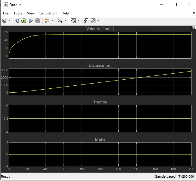
- As shown in first figure, velocity is increase gradually and become constant after some time for given fix throttle value. It is happening due to CVT. Fist of all CVT increase speen by engine rpm. After as given CVT ratio input with time, it changes gear ratio and reduce engine speed and making velocity constant at lower gear ratio. So, it will save fuel consumption. As see from chart that throttle value is constant.
- During this by integration we get distance travel by vehicle which is increased slowly but after some time get higher slope value.
- Brake is not applied so brake value is indicating 0.
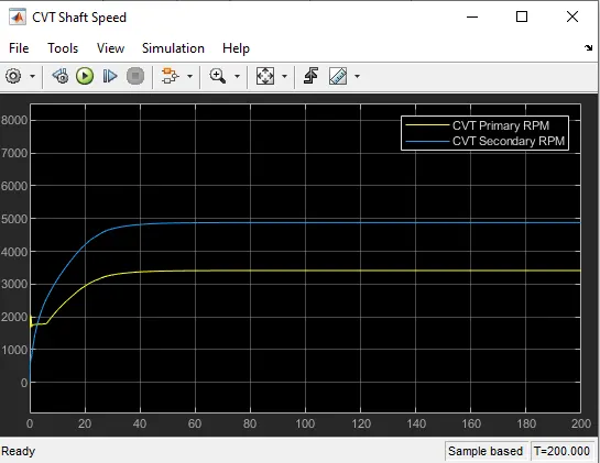
- According to second chart, we can observe that rpm of input shaft or primary shaft is less than secondary or output shaft.
- In starting, Primary rpm high but by setting CVT ratio to lower, primary shaft rpm become lesser than secondary shaft. And become steady at constant rpm.
So, like this model 1 is working and give output.
Program 2 :- With predefined CVT ratio and use defined throttle and brake input
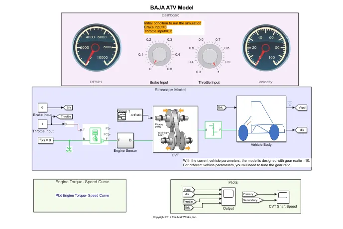
- Everything from structure to model working is same as above program. Only difference is input value of throttle and brake is defined by user by the time manually and program is computing output according to it.
- This program is running at infinite time.
- Also it has dashboard to give throttle and brake value and indicating screen for rpm and velocity.
-
Output :-
- As for user defined program run and computing output for input values.
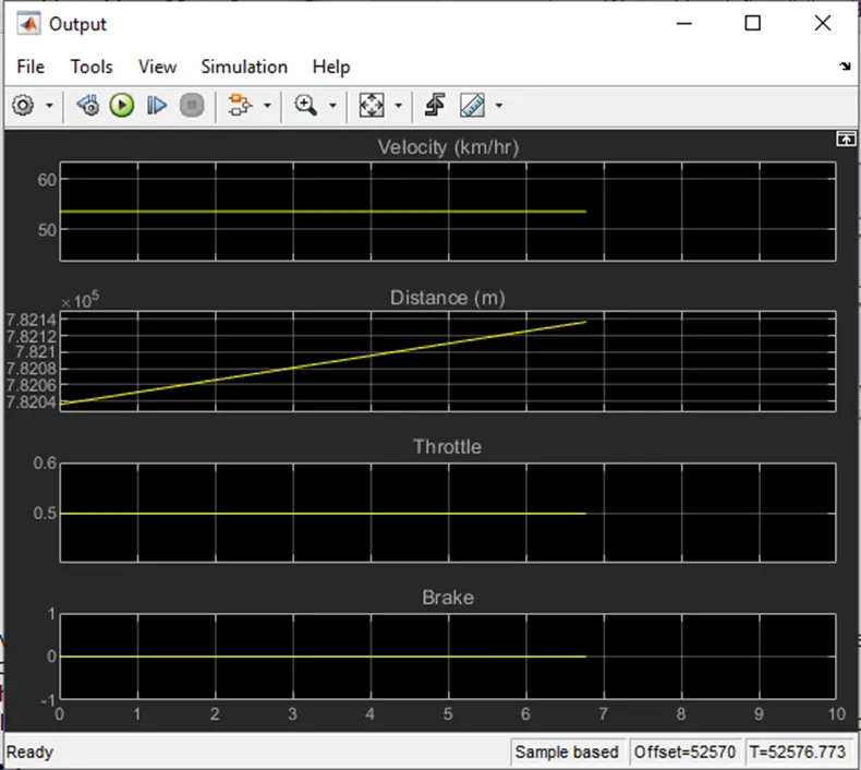
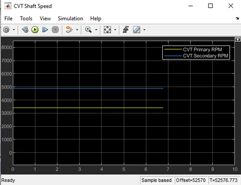
- 0.5 value is settled for this program also. It shows the same output data as above.
- Velocity is become constant and distance increasing continuously.
- Also CVT primary shaft has lesser rpm compare with secondary rpm shaft.
- Output is same as above due to same model with same input but only input value method is different.
So, like this this model run and give output.
Program 3 :- With predefined throttle and brake input and with CVT mapped ratio
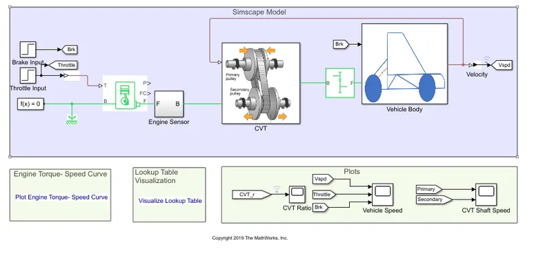
Working :
- In this model everything is same but only two things are different.
- First on is brake and throttle input given by step block instead of signal builder block. Which is already predefined.
- Second one CVT ratio is not given directly using signal builder block. For that this model get feedback from the vehicle output velocity or rpm and read predefined CVT ratio according to that rpm from lookup table which is in tabulated form. After reading value it gives CVT ratio to system
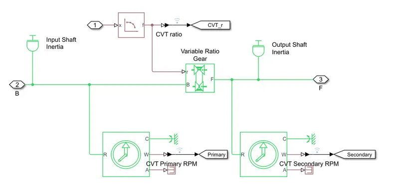
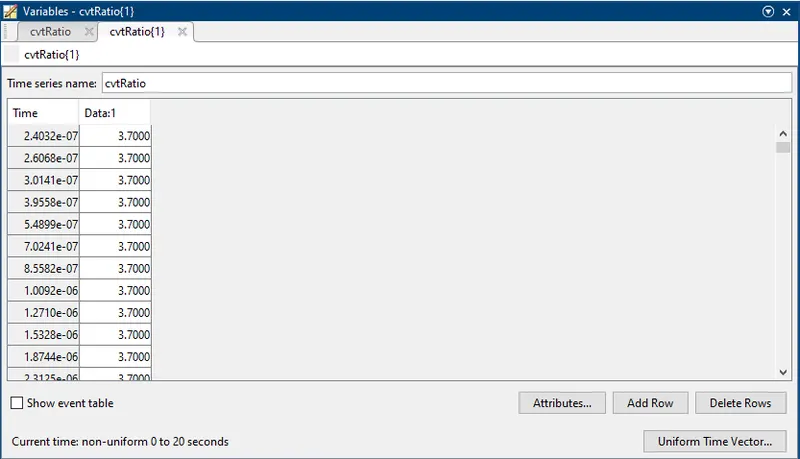
- Working of model is same as above program only these two difference are done.
Output :
CVT ratio :
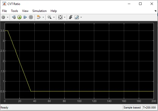
- After getting feedback CVT ratio is decrease a speed is increase as shown in figure which value is defined in liikup table.
Other Outputs :
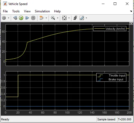
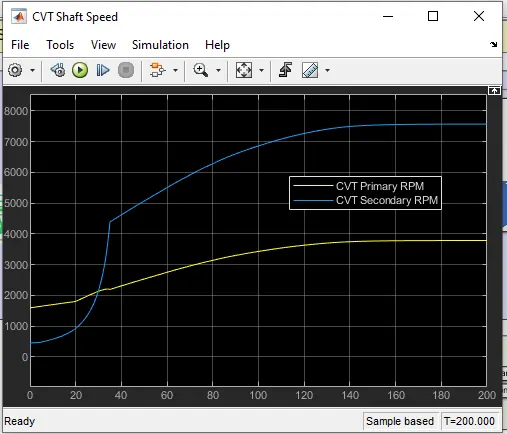
- According to plot, velocity is increase hyperbolically from start and become parabolic and then constant after some time for given throttle value.
- Here is also brake input is zero.
- As from above program, this model also shows same relationship between CVT primary and secondary shaft rpm.
- It shows that after fixed throttle open velocity is going higher due to CVT changing ration to lower side. So, we get high speed at lower engine speed.
Like this model 3 is working and showing output.
Program 4 :- With user defining throttle and brake input and with CVT mapped ratio
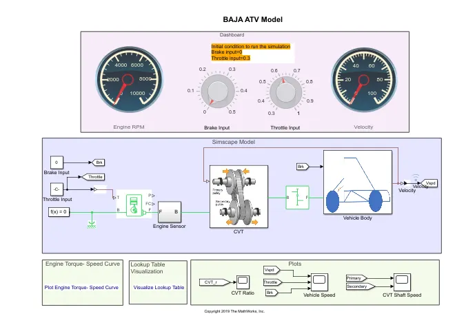
- This model is same as above. Only input value of throttle brake is not predefined. User can vary and get ouput value during the program running. It has dashboard with throttle and brake input changing knob and indicator of rpm and velocity.
- Working of this model is same as above instead of data input.
Output :
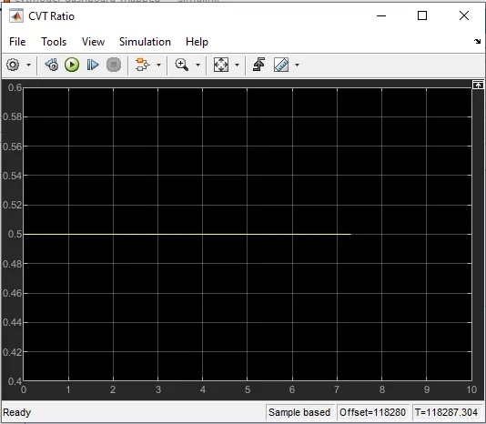
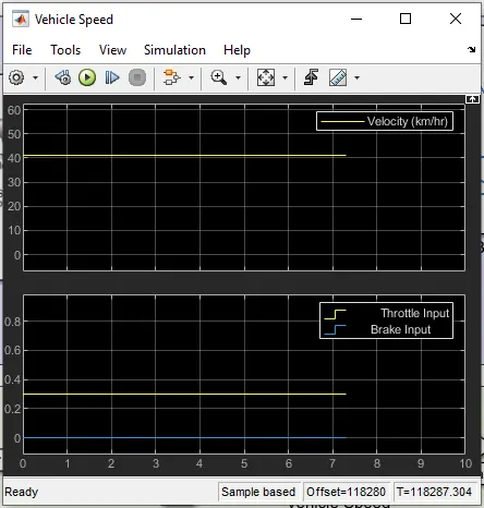
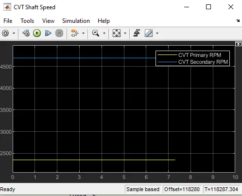
- As shown in figure output is same as above. Program is ran at same throttle value as above.
- From first figure we can see that CVT ratio becoming 0.5 constant as usual.
- Also velocityis becoming constant for given throttle value.
- Primary and Secondary CVT shaft is howing same relation as above programs.
So, this is how this model is working and computed outputs.
Finally, all four program are analysed with there outputs and also deifference of model building is highlighted. Outputs for all program are same.