Project 1- Traffic Jam Assistant Feature
To develop one specific requirement of Traffic Jam Assistant algorithm which would predominantly feature in the IPC algorithm.Please note that the whole Traffic Jam Assistant is a very huge algorithm & only one small part of the logic is implemented here. Idea is to familiarize with concepts of Model Based Development in MATLAB Environment. The Project must be done keeping in mind the following processes & steps.
- This model must be developed in MATLAB Simulink as per MBD guidelines.
- Code Generation Profile must be in Embedded Coder.
- Simulink Data Dictionary must be created for the model & must be linked to the model.
- Model Advisor Report is mandatory & this will be followed by Code Generation.
TJA is essentially a low-speed form of adaptive cruise control that helps make heavy traffic more comfortable. It detects vehicles ahead and automatically adjusts to their speeds using a front-mounted radar device, cameras, and sensors. TJA, on the other hand, takes action when a car approaches delayed traffic and slows to a crawl, as opposed to adaptive cruise control's purpose of maintaining highway cruising pace.
TJA is designed to operate at speeds less than 40 mph and will modify the vehicle's following distance based on the stop-and-go traffic ahead. To put it another way, the driver does not have to actively work the throttle or brake pedals while driving in heavy traffic. Without the need for human engagement, the TJA system will accelerate and decelerate the car on its own.
TJA will also come to a complete stop before resuming driving once the traffic ahead has moved. If the car has been entirely stationary for more than 30 seconds, most TJA systems need the driver to re-engage the system with a light tap to the gas pedal. This "reawakening" of the system ensures that the driver is paying attention to the overall traffic situation rather than simply tuning out because the vehicle has been idle for a long time.
Most TJA systems include lane-centering technology in addition to speed management to keep the vehicle from drifting. The system employs a camera to detect lane markers on the road surface and gives automatic steering inputs and modest modifications to keep the car in its lane. This feature assists drivers who may become drowsy and start drifting after long periods in slow traffic.
While using TJA and standard steering input, a motorist can make an intentional lane change at any time. The TJA system's lane-centering capability will be overridden by this step. After the car has changed lanes, the system will begin lane-centering by tracking the new lane's markings. After the driver has retake control of the steering, some TJA systems may require re-engagement. In the event of an emergency, all TJA systems allow for full driver override at any time.
The main model consist of 2 requirements as shown below,
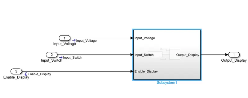
The input signals are Optimum_Voltage, Input_Switch,Enable_Display and in the requirement one the input voltage is compared to the voltage calibration values VOLTAGE_MINIMUM_RANGE & VOLTAGE_MAXIMUM_RANGE.The voltage minimum range and the input is compared by relational operator greater than or equal to block and the max range is compared by less than or equal to block,
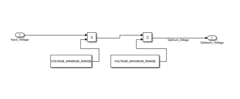
The output signal from this requirement is optimum voltage,
In the requirment 2 we have,
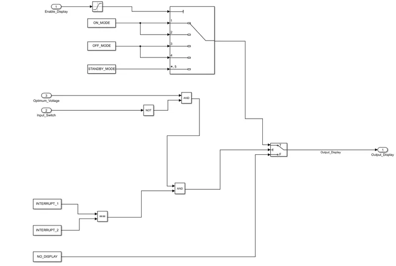
The input signals for this subsystem is Optimum_Voltage, Input_Switch,Enable_Display,
The enable display is connected to saturation block with min and max of value of 0-7 and is connected to multiport.The ON MODE is connected to 1 and 2 ports and OFF mode is connected to 3 and 4 ports ,Standby mode is connected to the no.5 port of the multiport.The output signal is connected to first input port of the switch block
The input switch is connected to NOT logical operator,and is compared with AND operator with the optimum voltage input signal,The interupt 1 and interupt 2 are compared with equal to relational block,and compared with the output signal coming from the optimum voltage and input switch,and given to the switch block ,The no display block is given to the third port of the switch.The output from the switch block is output display.
Now we have to create SLDD file and link the dictionary to the model,so we have to go the model settings and link the data dictionary,
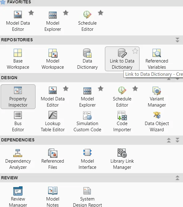
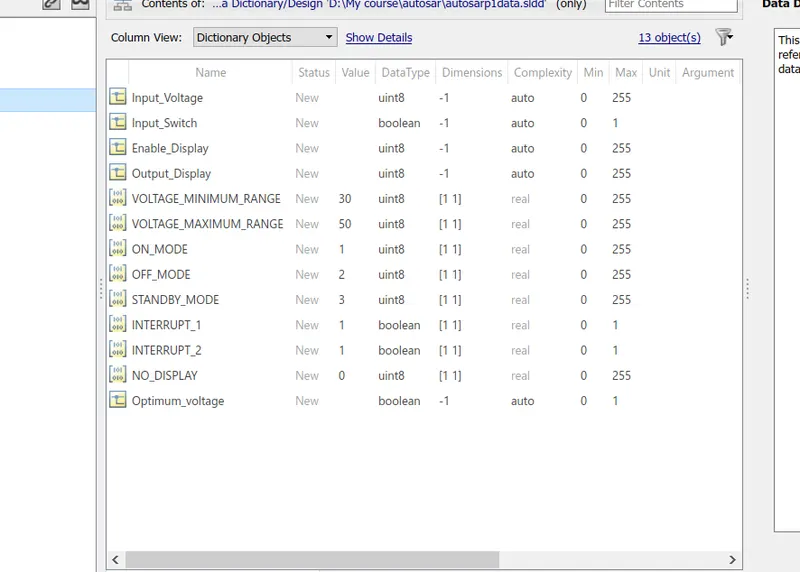
As we are given the calibration signals and input signal parameters we have to create the dictionary,
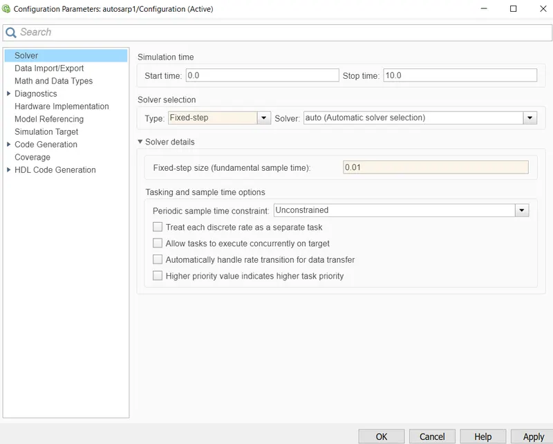
In the model settings we are changing the solver configuration,
We have build and generate the code for the model using embedded coder and the code is generated,
/*
 * File: Subsystem1.c
 *
 * Code generated for Simulink model 'Subsystem1'.
 *
 * Model version                  : 1.3
 * Simulink Coder version         : 9.5 (R2021a) 14-Nov-2020
 * C/C++ source code generated on : Wed Dec 15 10:28:33 2021
 *
 * Target selection: ert.tlc
 * Embedded hardware selection: Intel->x86-64 (Windows64)
 * Code generation objectives:
 *    1. Execution efficiency
 *    2. RAM efficiency
 * Validation result: Not run
 */

#include "Subsystem1.h"

/* External inputs (root inport signals with default storage) */
ExtU rtU;

/* External outputs (root outports fed by signals with default storage) */
ExtY rtY;

/* Model step function */
void Subsystem1_step(void)
{
  uint8_T tmp;

  /* Switch: '<S1>/Switch' incorporates:
   *  Inport: '<Root>/Input_Switch'
   *  Inport: '<Root>/Optimum_Voltage'
   *  Logic: '<S1>/Logical Operator'
   *  Logic: '<S1>/Logical Operator1'
   */
  if (rtU.Input_Switch && (!rtU.Optimum_Voltage)) {
    /* Saturate: '<S1>/Saturation' incorporates:
     *  Inport: '<Root>/Enable_Display'
     */
    if (rtU.Enable_Display < 7) {
      tmp = rtU.Enable_Display;
    } else {
      tmp = 7U;
    }

    /* End of Saturate: '<S1>/Saturation' */

    /* MultiPortSwitch: '<S1>/Multiport Switch' */
    switch (tmp) {
     case 1:
      /* Outport: '<Root>/Output_Display' incorporates:
       *  Constant: '<S1>/Constant'
       */
      rtY.Output_Display = 1U;
      break;

     case 2:
      /* Outport: '<Root>/Output_Display' incorporates:
       *  Constant: '<S1>/Constant'
       */
      rtY.Output_Display = 1U;
      break;

     case 3:
      /* Outport: '<Root>/Output_Display' incorporates:
       *  Constant: '<S1>/Constant1'
       */
      rtY.Output_Display = 2U;
      break;

     case 4:
      /* Outport: '<Root>/Output_Display' incorporates:
       *  Constant: '<S1>/Constant1'
       */
      rtY.Output_Display = 2U;
      break;

     default:
      /* Outport: '<Root>/Output_Display' incorporates:
       *  Constant: '<S1>/Constant2'
       */
      rtY.Output_Display = 3U;
      break;
    }

    /* End of MultiPortSwitch: '<S1>/Multiport Switch' */
  } else {
    /* Outport: '<Root>/Output_Display' incorporates:
     *  Constant: '<S1>/Constant3'
     */
    rtY.Output_Display = 0U;
  }

  /* End of Switch: '<S1>/Switch' */
}

/* Model initialize function */
void Subsystem1_initialize(void)
{
  /* (no initialization code required) */
}

/*
 * File trailer for generated code.
 *
 * [EOF]
 */
We have to perform the model advisor check using the model advisor tab,
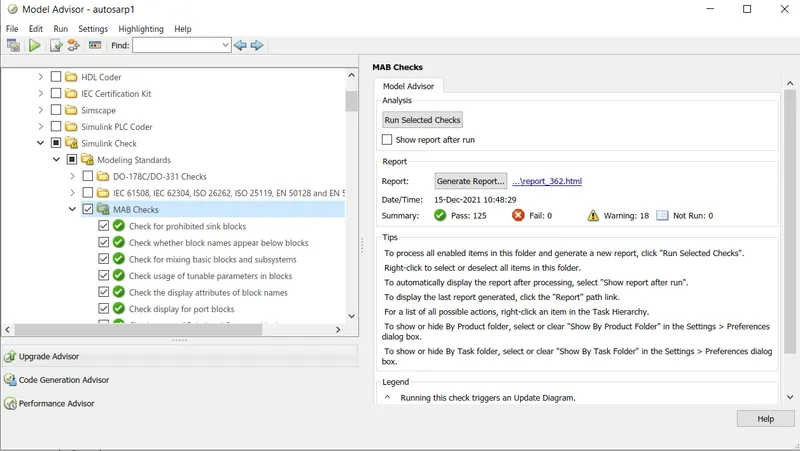
No error is found in the model and the the report is attached to the file.