Project 1- Traffic Jam Assistant Feature
Aim:
- To develop the model in MATLAB Simulink as per MBD guidelines.
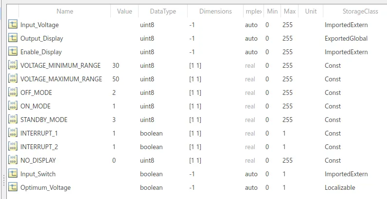
- To create Simulink Data Dictionary for the model and to be linked to the model.
- To create Model Advisor Report , by running the checks in MAAB
- To generate C code using embedded coder
SLDD Creation:
Create a new Simulink file. In model explorer click on New-->Data Dictionary
Requirement No 1:
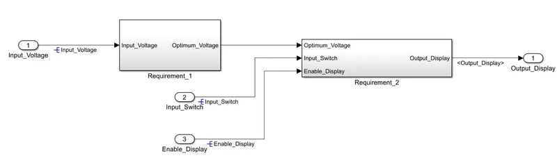
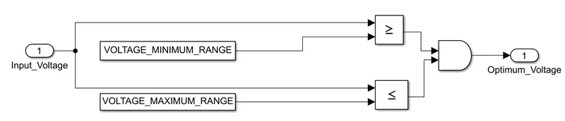
- Input Signal “Input_Voltage” is compared against voltage values “VOLTAGE_MINIMUM_RANGE” & “VOLTAGE_MAXIMUM_RANGE”.
- Incoming input signal “Input_Voltage” must be greater than – equal to “VOLTAGE_MINIMUM_RANGE” and less than – equal to “VOLTAGE_MAXIMUM_RANGE”.
- Output signal from here is “Optimum_Voltage” which will be one of the inputs to the subsystem “DisplayUnit”.
Requirement No 2 (DisplayUnit Subsystem):
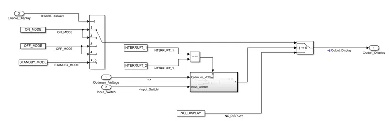
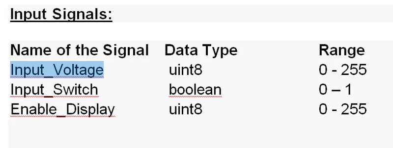
- Input Signals are “Optimum_Voltage”, “Input_Switch”,“Enable_Display”. Signal “Enable_Display” must be saturated between the range 0 – 7. Output signal from the subsystem is “Output_Display”.
- Input Signal “Enable_Display” is compared against pre – defined set of values in a multiport switch. Total data ports in the multiport switch is 5.
- Multiport switch inputs 1 & 2 is connected to calibration signal “ON_MODE”, Multiport switch inputs 3 & 4 is connected to calibration signal “OFF_MODE” while Multiport switch input 5 is connected to calibration signal “STANDBY_MODE”.
- The output from Multiport switch is connected to the first input port of the Switch block. The third input port of the Switch block is connected to the calibration signal “NO_DISPLAY”.
- Meanwhile NOT value of input signal “Input_Switch” is compared in an AND gate against input signal “Optimum_Voltage” and the output from comparing if calibration signals “INTERRUPT_1” & “INTERRUPT_2” are equal. The output of the AND gate is the second input of the switch block.
- The output from the switch block is “Output_Display”.
Requirement Tagging:
Select the text in the word file.
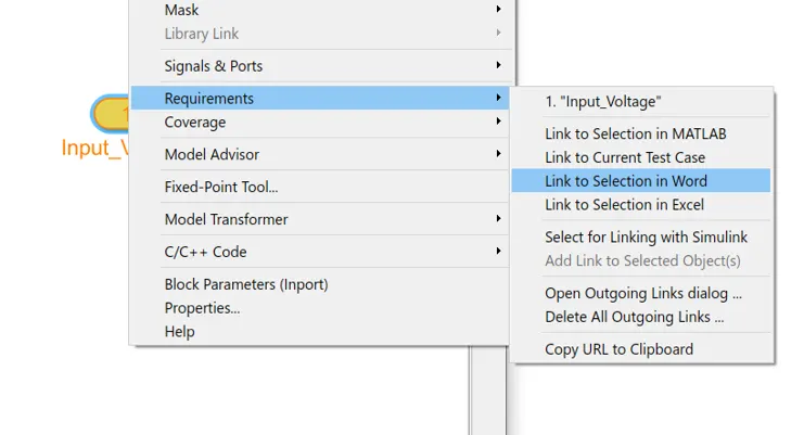
Now right click on the subsystem in matlab, and go to requirements
Click on link to select in word
Repeat the same procedure for the subsystems and the signals
MAAB Check:
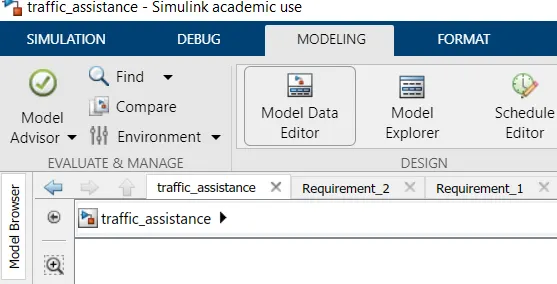
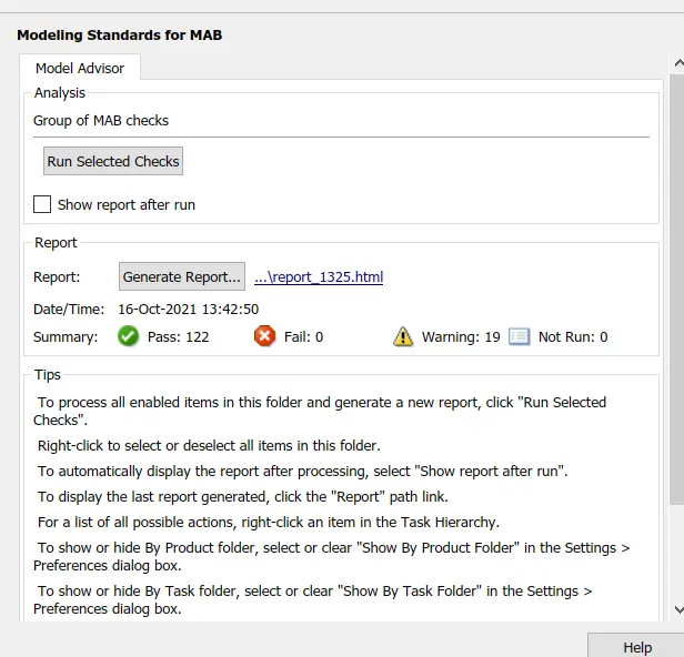
Click on Modeling --> Model Advisor
Now check on the the Modeling Standards for MAB
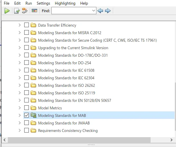
Click on Run Selected checks
Code Generation:
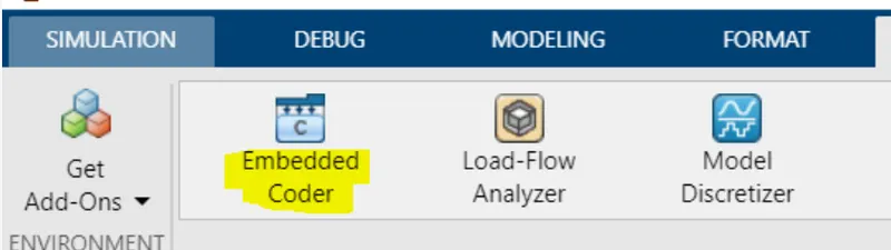
Click on Apps ---> Embedded coder
Change the solver to fixed step solver.
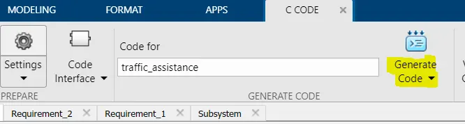
Click on C Code ---> Generate code
C Code:
/*
 * Academic License - for use in teaching, academic research, and meeting
 * course requirements at degree granting institutions only.  Not for
 * government, commercial, or other organizational use.
 *
 * File: traffic_assistance.c
 *
 * Code generated for Simulink model 'traffic_assistance'.
 *
 * Model version                  : 1.17
 * Simulink Coder version         : 9.4 (R2020b) 29-Jul-2020
 * C/C++ source code generated on : Sat Oct 16 11:44:09 2021
 *
 * Target selection: ert.tlc
 * Embedded hardware selection: Intel->x86-64 (Windows64)
 * Code generation objectives: Unspecified
 * Validation result: Not run
 */

#include "traffic_assistance.h"
#include "traffic_assistance_private.h"

/* Exported block signals */
uint8_T Output_Display;                /* '/Switch' */

/* Exported data definition */

/* Const memory section */
/* Definition for custom storage class: Const */
const boolean_T INTERRUPT_1 = 1;       /* Referenced by: '/Constant4' */
const boolean_T INTERRUPT_2 = 1;       /* Referenced by: '/Constant5' */
const uint8_T NO_DISPLAY = 0U;         /* Referenced by: '/Constant3' */
const uint8_T OFF_MODE = 2U;           /* Referenced by: '/Constant1' */
const uint8_T ON_MODE = 1U;            /* Referenced by: '/Constant' */
const uint8_T STANDBY_MODE = 3U;       /* Referenced by: '/Constant2' */
const uint8_T VOLTAGE_MAXIMUM_RANGE = 50U;/* Referenced by: '/Constant1' */
const uint8_T VOLTAGE_MINIMUM_RANGE = 30U;/* Referenced by: '/Constant' */

/* Block signals (default storage) */
B_traffic_assistance_T traffic_assistance_B;

/* Real-time model */
static RT_MODEL_traffic_assistance_T traffic_assistance_M_;
RT_MODEL_traffic_assistance_T *const traffic_assistance_M =
  &traffic_assistance_M_;

/* Model step function */
void traffic_assistance_step(void)
{
  /* Outputs for Enabled SubSystem: '/Subsystem' incorporates:
   *  EnablePort: '/Enable'
   */
  /* RelationalOperator: '/Equal' incorporates:
   *  Constant: '/Constant4'
   *  Constant: '/Constant5'
   */
  if (INTERRUPT_1 == INTERRUPT_2) {
    /* Logic: '/AND' incorporates:
     *  Constant: '/Constant'
     *  Constant: '/Constant1'
     *  Inport: '/Input_Switch'
     *  Inport: '/Input_Voltage'
     *  Logic: '/AND'
     *  Logic: '/NOT'
     *  RelationalOperator: '/Less Than'
     *  RelationalOperator: '/Less Than1'
     */
    traffic_assistance_B.AND = ((!Input_Switch) && ((Input_Voltage >=
      VOLTAGE_MINIMUM_RANGE) && (Input_Voltage <= VOLTAGE_MAXIMUM_RANGE)));
  }

  /* End of RelationalOperator: '/Equal' */
  /* End of Outputs for SubSystem: '/Subsystem' */

  /* Switch: '/Switch' */
  if (traffic_assistance_B.AND) {
    /* MultiPortSwitch: '/Multiport Switch' incorporates:
     *  Inport: '/Enable_Display'
     */
    switch (Enable_Display) {
     case 1:
      /* Switch: '/Switch' incorporates:
       *  Constant: '/Constant'
       */
      Output_Display = ON_MODE;
      break;

     case 2:
      /* Switch: '/Switch' incorporates:
       *  Constant: '/Constant'
       */
      Output_Display = ON_MODE;
      break;

     case 3:
      /* Switch: '/Switch' incorporates:
       *  Constant: '/Constant1'
       */
      Output_Display = OFF_MODE;
      break;

     case 4:
      /* Switch: '/Switch' incorporates:
       *  Constant: '/Constant1'
       */
      Output_Display = OFF_MODE;
      break;

     default:
      /* Switch: '/Switch' incorporates:
       *  Constant: '/Constant2'
       */
      Output_Display = STANDBY_MODE;
      break;
    }

    /* End of MultiPortSwitch: '/Multiport Switch' */
  } else {
    /* Switch: '/Switch' incorporates:
     *  Constant: '/Constant3'
     */
    Output_Display = NO_DISPLAY;
  }

  /* End of Switch: '/Switch' */
}

/* Model initialize function */
void traffic_assistance_initialize(void)
{
  /* (no initialization code required) */
}

/* Model terminate function */
void traffic_assistance_terminate(void)
{
  /* (no terminate code required) */
}

/*
 * File trailer for generated code.
 *
 * [EOF]
 */
Result:
Thus all the requirements of the project are satisfied successfully , MAAB Check has been completed and C Code is generated.