Project 1 (Mini Project on Vehicle Direction Detection
Aim:
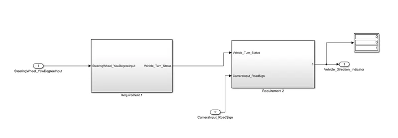
To detect the vehicle direction from the inputs from steering wheel yaw degree input and road sign using Simulink.
Simulink Model:
Methodlology:
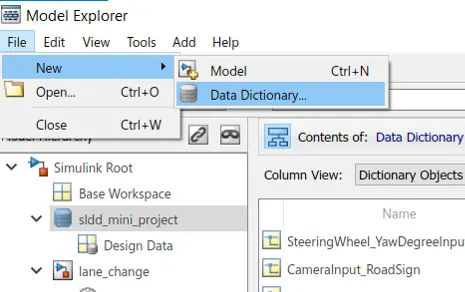
Create a new Simulink file. In model explorer click on New-->Data Dictionary
Input the signals and data as given:
|
Signal / Calibration Name |
Signal Type |
Data Type |
Dimension |
Min |
Max |
Initial Value |
Units |
|
SteeringWheel_YawDegreeInput |
Input |
Int16 |
1 |
-180 |
180 |
- |
Deg |
|
CameraInput_RoadSign |
Input |
Boolean |
1 |
0 |
1 |
- |
- |
|
Vehicle_Turn_Status |
Local |
Int16 |
1 |
-180 |
180 |
- |
Deg |
|
Right_Turn_AngularLimit |
Calibration |
Int16 |
[1 1] |
-180 |
180 |
30 |
Deg |
|
Left_Turn_AngularLimit |
Calibration |
Int16 |
[1 1] |
-180 |
180 |
-120 |
Deg |
|
Straight_Drive_Steering_Angle |
Calibration |
Int16 |
[1 1] |
-180 |
180 |
0 |
Deg |
|
RightTurn_RoadSign |
Calibration |
Int16 |
[1 1] |
-180 |
180 |
30 |
|
|
LeftTurn_RoadSign |
Calibration |
Int16 |
[1 1] |
-180 |
180 |
-120 |
|
|
Straight_RoadSign |
Calibration |
Int16 |
[1 1] |
-180 |
180 |
0 |
|
|
Vehicle_Direction_Indicator |
Output |
Boolean |
1 |
0 |
1 |
- |
- |
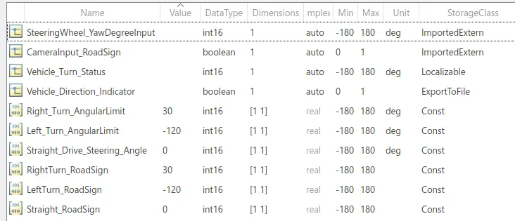
Now the SLDD file is created and saved.
Requirement 1 :
- Steering wheel input as yaw rate (Signal name: SteeringWheel_YawDegreeInput) is the input for this system.
- This is compared against 3 angular values, one each for left turn, right turn & straight drive (Calibration Values: Right_Turn_AngularLimit, Left_Turn_AngularLimit, Straight_Drive_Steering_Angle) to say which specific direction the steering wheel is turning towards.
- Use switch blocks to compare & develop this requirement. Keep this requirement in a subsystem & output of this requirement is a local signal (Signal Name: Vehicle_Turn_Status).
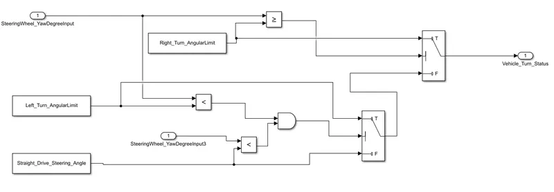
Firstly, the steering input is detected. It is compared with the angle limits so that the vehicle turn status is found. In other words, for a right turn the steering angle should be greater than 30 deg and for left turn the value should be greater than -120 deg(for eg: -130 deg ) If the value is between -120 deg and 30 deg , then the turn status would be straight.
This range is computed using switch blocks as shown below:
Thus the requirement 1 has been satisfied.
Requirement 2:
- Keep this requirement as a separate subsystem. Inputs to this requirement are local signal from requirement 1 (Signal Name: Vehicle_Turn_Status) & an input signal from camera (Signal Name: CameraInput_RoadSign), which confirms the occurrence of a road sign.
- Signal Vehicle_Turn_Status is compared against calibration values (Calibration Values: RightTurn_RoadSign, LeftTurn_RoadSign, Straight_RoadSign), if each of them is found equal, then each of the three corresponding output is compared against the camera input signal,
- Using a logical operator block, only one among them is finally given as output signal (Signal Name: Vehicle_Direction_Indicator).
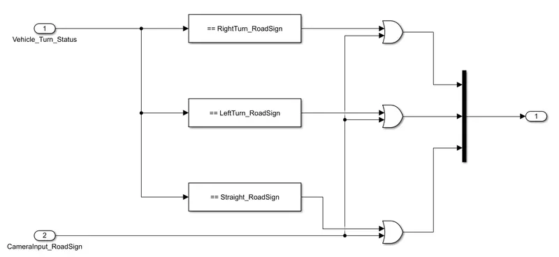
Now a new subsystem has been created. Then vehicle turn status is compared with each of the road signs using equal to block . These outputs are compared with the inputs from the camera using the OR gate.
The outputs are fed into a Mux block.
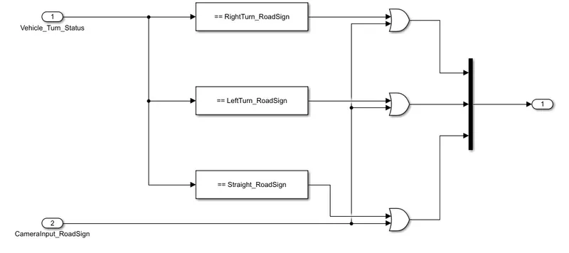
This satisfies the requirement 2.
The model is made to run and output obtained is 0,0,1. This indicates the vehicle moves in straight direction.
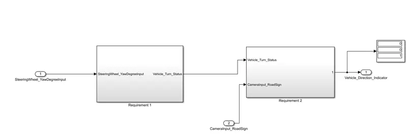
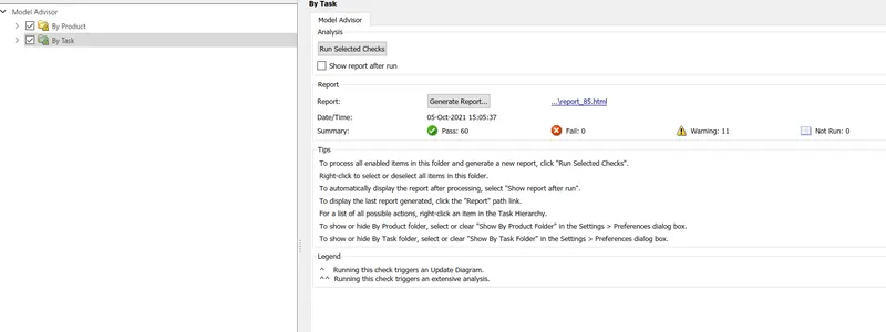
Now go to model advisor and check on the By product and By task boxes. Click on run selected checks.
Result:
Thus the requirements are satisied and the model advisor check is passed.