Project 1- Traffic Jam Assistant Feature
AIM:-
To develop one specific requirement of Traffic Jam Assistant algorithm.
OBJECTIVE:-
1) To develop one specific requirement of Traffic Jam Assistant algorithm which would predominantly feature in the IPC algorithm.
2) To develop Simulink model as per MBD requirements, Code Generation Profile in Embedded Coder, create Simulink Data Dictionary and generate Model Advisor Report according to MAAB guidelines.
Traffic Jam Assistance (TJA):-
Traffic Jam Assistance (TJA) is an advanced driver assistance system that continuously measures the speed of the surrounding vehicles when Adaptive Cruise Control is switched on. That speed is compared with your own driving speed. If Traffic Jam Assistance detects many surrounding vehicles at speeds below 60 km/h – and you are therefore very likely to be in a traffic jam – the driver can activate Traffic Jam Assistance. With this, your MG partly takes over the driving.

With Traffic Jam Assistance switched on, the car automatically follows the vehicle in front. It accelerates and brakes all by itself, at all speeds below 60 km/h to a standstill and further. In addition, the intelligent technology continuously keeps the distance you set to the vehicle in front of you. But there is more: with Traffic Jam Assistance, your MG also steers automatically to stay neatly in the middle of the lane. Even in gentle corners! Very comfortable, carefree and safe driving, regardless the visibility, the weather conditions and the amount of traffic on the road.
How it works (Watch video):-
https://res.cloudinary.com/mgmotor/video/upload/f_auto,q_auto/v1645787354/news/MG-Pilot-Traffic-Jam-Assistance.mp4?_i=AA
Basic Working Principle:
Traffic Jam Assistant is based on the sensors and the functionality of the Adaptive Cruise Control (ACC) with stop & go and Lane Keeping Support (LKS). When ACC ‘Stop & Go’ is turned ON, the Traffic Jam Assistant continuously analyses the speed of the surrounding vehicles and compares it with the own driving speed. If the system detects dense traffic or a traffic jam at speeds less than 60 kmph, the driver can activate the functionality by press of a button. The vehicle will now automatically follow the vehicle in front, takes over driving off, acceleration, braking and steering within same lane.
Information regarding the Traffic Jam Assistant will be available to be displayed to the driver in the Instrument Panel Cluster (IPC). The Algorithm which the students need to implement here in this project is predominantly based on IPC units.
Model Simulation:-
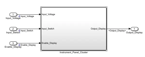
The Traffic jam assistance simulation model is created in MATLAB enviornment. A subsystem consist of 3 inputs and one output. Inputs signals are "Input_Voltage", "Input_Switch", & "Enable_Display" and output signal is "Output_Display".
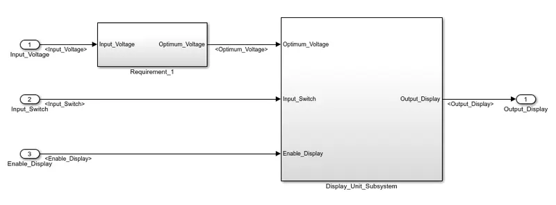
Going inside main subsystem it has 2 more subsystem namely Requirement_1 & Dispaly_Unit_Subsystem
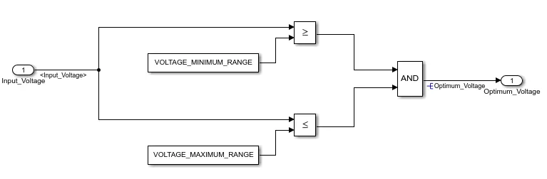
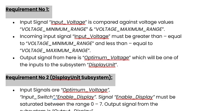
Requirement No 1:-
- Input Signal “Input_Voltage” is compared against voltage values “VOLTAGE_MINIMUM_RANGE” & “VOLTAGE_MAXIMUM_RANGE”.
- Incoming input signal “Input_Voltage” must be greater than – equal to “VOLTAGE_MINIMUM_RANGE” and less than – equal to “VOLTAGE_MAXIMUM_RANGE”.
- Output signal from here is “Optimum_Voltage” which will be one of the inputs to the subsystem “DisplayUnit”.
Requirement No 2 (DisplayUnit Subsystem):
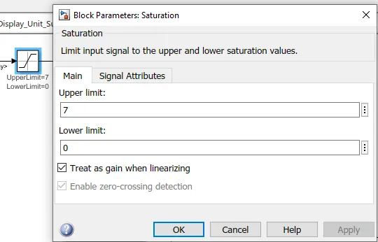
- Input Signals are “Optimum_Voltage”, “Input_Switch”,“Enable_Display”. Signal “Enable_Display” must be saturated between the range 0 – 7. Output signal from the subsystem is “Output_Display”.
- Input Signal “Enable_Display” is compared against pre – defined set of values in a multiport switch. Total data ports in the multiport switch is 5.
- Multiport switch inputs 1 & 2 is connected to calibration signal “ON_MODE”, Multiport switch inputs 3 & 4 is connected to calibration signal “OFF_MODE” while Multiport switch input 5 is connected to calibration signal “STANDBY_MODE”.
- The output from Multiport switch is connected to the first input port of the Switch block. The third input port of the Switch block is connected to the calibration signal “NO_DISPLAY”.
- Meanwhile NOT value of input signal “Input_Switch” is compared in an AND gate against input signal “Optimum_Voltage” and the output from comparing if calibration signals “INTERRUPT_1” & “INTERRUPT_2” are equal. The output of the AND gate is the second input of the switch block.
- The output from the switch block is “Output_Display”.
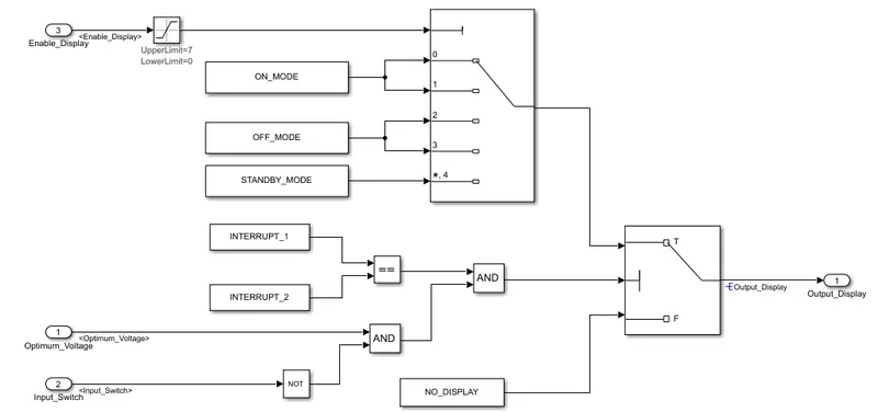
Enable Signal having maximum and minimum range as specified in requirement document and that can be modified in Block parameters.
Creating Simulink Data Dictionary (SLDD):-
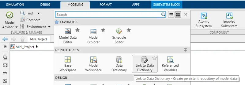
To create SLDD file goto Modelling tab > Design > Link to Data Dictionary
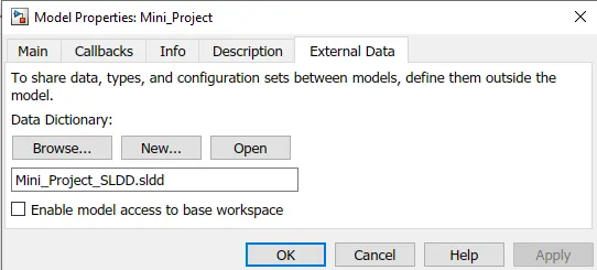
Now create new SLDD file and give it as name.
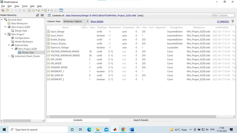
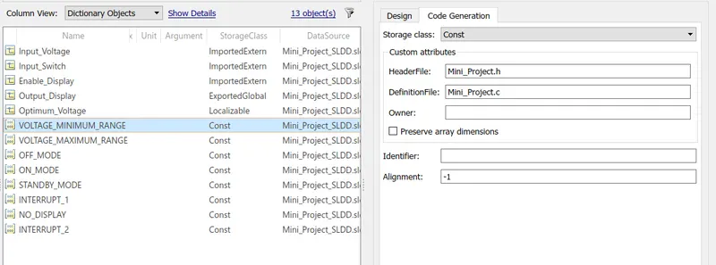
- As per requirement, all signals and constants are defined in Simulink Data Dictionary (SLDD).
- For input signals-Storage class is ImportedExtern, For output signal- Storage class is ExportedGlobal, For local signals- Storage class is Localizable and For constants- Storage class is Const.
For code generation, Header and definition files are defined as shown below,
Requirement Tagging:-
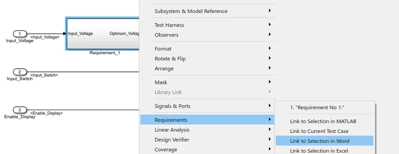
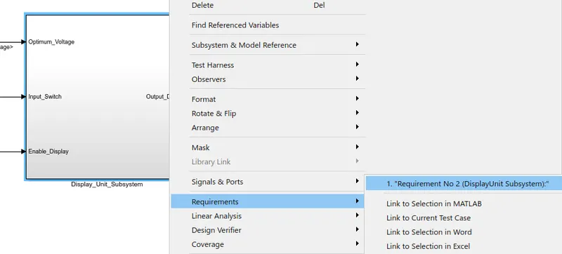
Select the Requirement name from the word file and then go to matlab model, Right click on the 'Requirement_01' subsytem and goto 'Requirements>> Link to Selection in Word'.
Model Configuration Settings:-
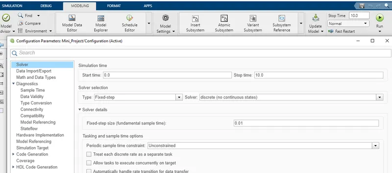
Solver Setting:- Solver should be Fixed step discreate with step size of 0.01 sec.
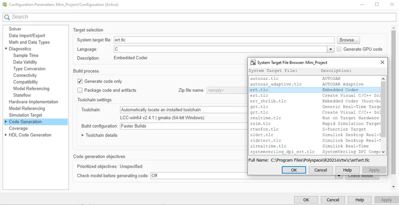
Code Generation:- Selected the system file as ert.tlc which is for Embedded coder.
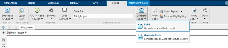
To generate Code goto APPs > Embedded Coder

Click on build to generate code
Main file, Model files, Data files and Utility files will generate as shown below:
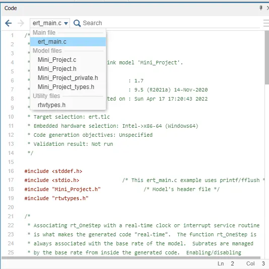
Data File: ert_main.c
/*
 * File: ert_main.c
 *
 * Code generated for Simulink model 'Mini_Project'.
 *
 * Model version                  : 1.7
 * Simulink Coder version         : 9.5 (R2021a) 14-Nov-2020
 * C/C++ source code generated on : Sun Apr 17 17:20:43 2022
 *
 * Target selection: ert.tlc
 * Embedded hardware selection: Intel->x86-64 (Windows64)
 * Code generation objectives: Unspecified
 * Validation result: Not run
 */

#include <stddef.h>
#include <stdio.h>              /* This ert_main.c example uses printf/fflush */
#include "Mini_Project.h"              /* Model's header file */
#include "rtwtypes.h"

/*
 * Associating rt_OneStep with a real-time clock or interrupt service routine
 * is what makes the generated code "real-time".  The function rt_OneStep is
 * always associated with the base rate of the model.  Subrates are managed
 * by the base rate from inside the generated code.  Enabling/disabling
 * interrupts and floating point context switches are target specific.  This
 * example code indicates where these should take place relative to executing
 * the generated code step function.  Overrun behavior should be tailored to
 * your application needs.  This example simply sets an error status in the
 * real-time model and returns from rt_OneStep.
 */
void rt_OneStep(void);
void rt_OneStep(void)
{
  static boolean_T OverrunFlag = false;

  /* Disable interrupts here */

  /* Check for overrun */
  if (OverrunFlag) {
    rtmSetErrorStatus(Mini_Project_M, "Overrun");
    return;
  }

  OverrunFlag = true;

  /* Save FPU context here (if necessary) */
  /* Re-enable timer or interrupt here */
  /* Set model inputs here */

  /* Step the model */
  Mini_Project_step();

  /* Get model outputs here */

  /* Indicate task complete */
  OverrunFlag = false;

  /* Disable interrupts here */
  /* Restore FPU context here (if necessary) */
  /* Enable interrupts here */
}

/*
 * The example "main" function illustrates what is required by your
 * application code to initialize, execute, and terminate the generated code.
 * Attaching rt_OneStep to a real-time clock is target specific.  This example
 * illustrates how you do this relative to initializing the model.
 */
int_T main(int_T argc, const char *argv[])
{
  /* Unused arguments */
  (void)(argc);
  (void)(argv);

  /* Initialize model */
  Mini_Project_initialize();

  /* Attach rt_OneStep to a timer or interrupt service routine with
   * period 0.01 seconds (the model's base sample time) here.  The
   * call syntax for rt_OneStep is
   *
   *  rt_OneStep();
   */
  printf("Warning: The simulation will run forever. "
         "Generated ERT main won't simulate model step behavior. "
         "To change this behavior select the 'MAT-file logging' option.\n");
  fflush((NULL));
  while (rtmGetErrorStatus(Mini_Project_M) == (NULL)) {
    /*  Perform other application tasks here */
  }

  /* Disable rt_OneStep() here */

  /* Terminate model */
  Mini_Project_terminate();
  return 0;
}

/*
 * File trailer for generated code.
 *
 * [EOF]
 */
Model Advisory Report:-
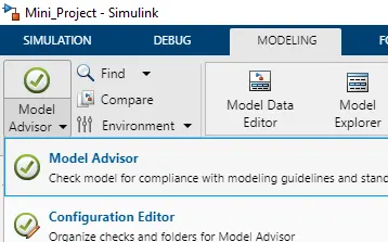
Goto Modelling Tab > Model Advisor
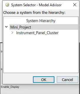
Selecting Top Hierachy and then OK
Here 2 tabs appear, Product & Tasks, Click on Task button.
Under Task option click on Modeling Standards for MAB.
Run selected checks; In summary, no of pass, fail, warning and Not rum will display
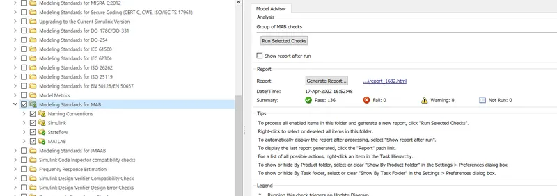
- To generate Report, click on 'Generate Report' and select desired format as shown below:
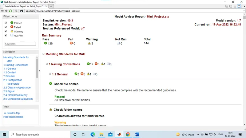
Conclusion:-
- Simulink modelling, Requirement Tagging, Code Generation, SLDD and Model advisor Report all the processes of MBD are performed.
- In Model advisor Report, 136 out of 144 test passed with 8 warnings according to MAAB guidelines.