Project 1- Traffic Jam Assistant Feature
Traffic Jam Assistant Feature
Working procedure
This model must be developed in MATLAB Simulink as per MBD guidelines according to the requirements given.
Tag the requirements to the Simulink model, Requirements 1 & Requirement 2 are tagged into their corresponding subsystems.
Creation of Simulink Data Dictionary for the model & must be linked to the model.
Tagging for Requirement 1 and Requirement2 subsystem.
Creation of Model Advisor Report for given Traffic Jam Assistant Feature model. Code Generation Profile must be in Embedded Coder
Traffic Jam Assist feature brakes and accelerates the car for the driver, while maintaining a safe distance from the vehicle in front.
The driver has to permanently supervise the system & be ready to take over the complete control of the vehicle at any time
Main Model
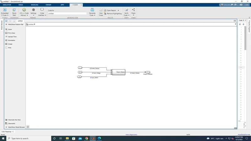
this is the main model, with three inport and one outport
And resolve the signals like this
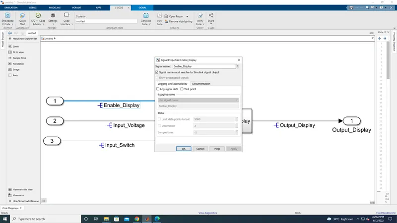
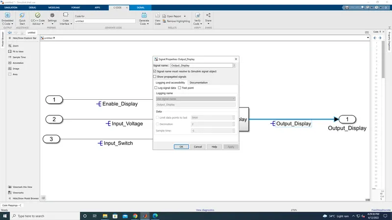
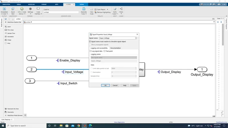
same thing you have to do for output also
resole the signal with name which was given in the requirement
Now double click on the subsystem, and seems like this
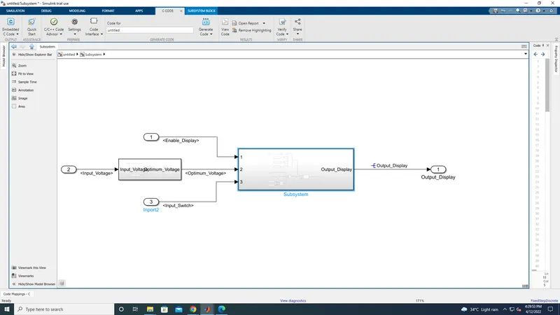
As per requirement given in the question, need to create a subsystem in and the output of the subsystem is connected with the requirement 2
Inside the subsystem we need to propagate the signal which we have initialy resolved in main model
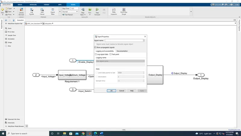
like this we have to propagate the signals for other input also
Condition for Requirement 1
Requirement No 1:
- Input Signal “Input_Voltage” is compared against voltage values “VOLTAGE_MINIMUM_RANGE” & “VOLTAGE_MAXIMUM_RANGE”.
- Incoming input signal “Input_Voltage” must be greater than – equal to “VOLTAGE_MINIMUM_RANGE” and less than – equal to “VOLTAGE_MAXIMUM_RANGE”.
- Output signal from here is “Optimum_Voltage” which will be one of the inputs to the subsystem “DisplayUnit”.
Now name the subsystem as requirement 1
and double on the subsystem
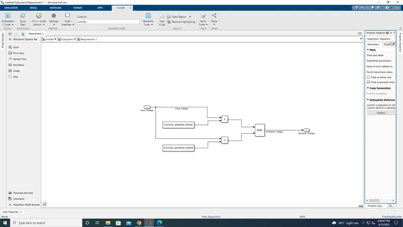
Input Signal <Input_Voltage> is compared against voltage values VOLTAGE_MINIMUM_RANGE & VOLTAGE_MAXIMUM_RANGE.
Incoming input signal <Input_Voltage> must be greater than – equal to VOLTAGE_MINIMUM_RANGE and less than – equal to
VOLTAGE_MAXIMUM_RANGE.
Output signal from here is <Optimum_Voltage> which will be one of the inputs to the subsystem DisplayUnit.
However, output signal (i.e Optimum_Voltage) is form newly in this subsystem hence we resolve this signal by right clicking on signal
properties
and need to resolve the signal for Optimum-voltage on output
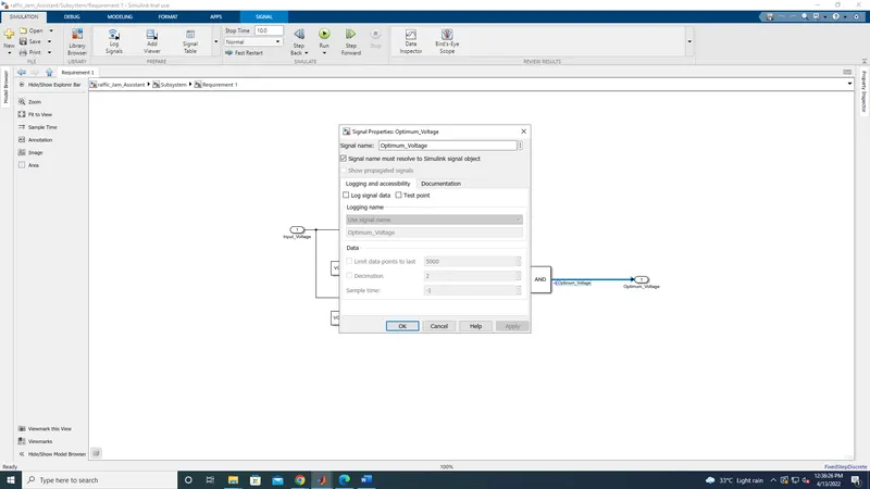
Now propagate the signal on output and need to connect it with requirement 2
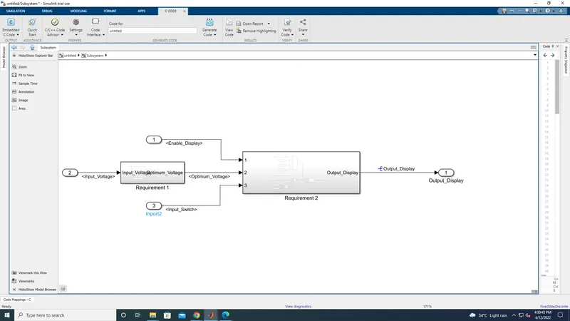
Requirement No 2 (DisplayUnit Subsystem):
- Input Signals are “Optimum_Voltage”, “Input_Switch”,“Enable_Display”. Signal “Enable_Display” must be saturated between the range 0 – 7. Output signal from the subsystem is “Output_Display”.
- Input Signal “Enable_Display” is compared against pre – defined set of values in a multiport switch. Total data ports in the multiport switch is 5.
- Multiport switch inputs 1 & 2 is connected to calibration signal “ON_MODE”, Multiport switch inputs 3 & 4 is connected to calibration signal “OFF_MODE” while Multiport switch input 5 is connected to calibration signal “STANDBY_MODE”.
- The output from Multiport switch is connected to the first input port of the Switch block. The third input port of the Switch block is connected to the calibration signal “NO_DISPLAY”.
- Meanwhile NOT value of input signal “Input_Switch” is compared in an AND gate against input signal “Optimum_Voltage” and the output from comparing if calibration signals “INTERRUPT_1” & “INTERRUPT_2” are equal. The output of the AND gate is the second input of the switch block.
- The output from the switch block is “Output_Display”.
Now double click on the subsystem 2 which was named as requirement 2, And inside the requirement 2 it seems like this
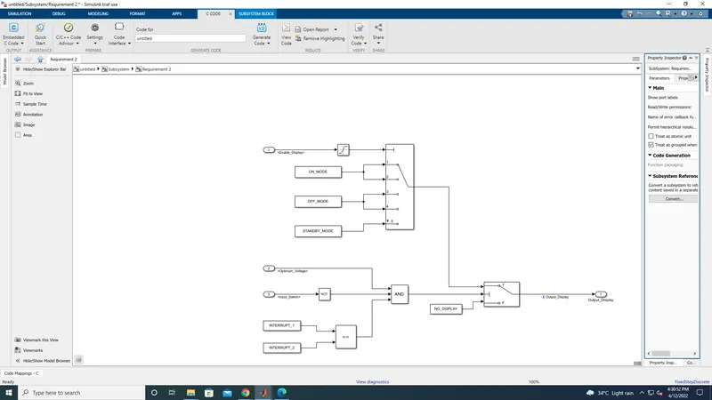
As per given requirement
saturation block been with inport and output has been connceted with multiport switch 1
and set the lower range as 0 and upper range as 7
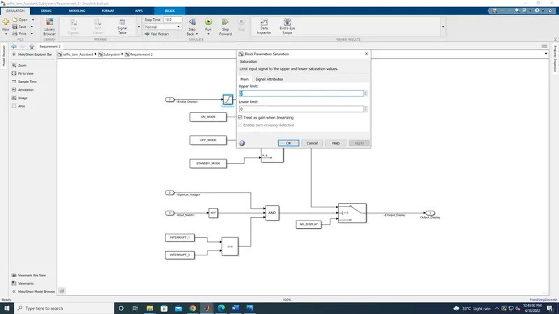
create a multiport switch and set a number of switch port as 5
Now create a three constant block
and name it as ON_MODE, OFF_MODE, STANDBY_MODE
now connect ON_MODE block in switch 1 & 2
then connect OFF_MODE block in switch in 3 & 4
and finally connect STANDY_MODE block in switch 5
as per the condition given in the question
Now for Inport 2 & 3
it has been connect with and block
Inport 2 directly connect to And block and Inport 3 connect with not block and then it connect with and block
And finally INTERRUPT 1 & 2 is connected with relational operator with double equal and then it connected with And block
Now the Multiport output and and block output connect with switch block
and it will give excepted output while run the program
Thus the Requiremt & 2 been fully explained
Now need to chech MAB guidline for this model
Before that need to add Data dictonary for the model
For that Signals and parameters has been given in the model
Input Signals:
|
Name of the Signal |
Data Type |
Range |
|
Input_Voltage |
uint8 |
0 - 255 |
|
Input_Switch |
boolean |
0 – 1 |
|
Enable_Display |
uint8 |
0 - 255 |
Output Signal:
|
Name of the Signal |
Data Type |
Range |
|
Output_Display |
uint8 |
0 - 255 |
Calibration Signals:
|
Name of the Signal |
Data Type |
Range |
Initial Value |
|
VOLTAGE_MINIMUM_RANGE |
uint8 |
0 – 255 |
30 |
|
VOLTAGE_MAXIMUM_RANGE |
uint8 |
0 – 255 |
50 |
|
OFF_MODE |
uint8 |
0 – 255 |
2 |
|
ON_MODE |
uint8 |
0 – 255 |
1 |
|
STANDBY_MODE |
uint8 |
0 – 255 |
3 |
|
INTERRUPT_1 |
boolean |
0 – 1 |
1 |
|
INTERRUPT_2 |
boolean |
0 - 1 |
1 |
|
NO_DISPLAY |
uint8 |
0 – 255 |
0 |
Local Signal:
|
Name of the Signal |
Data Type |
Range |
|
Optimum_Voltage |
boolean |
0 - 1 |
In SLDD Local signals, Input signals, output signals been taken in signal block
And calibration been taken in Parameter block
To create a SLDD file first we need to create a new SLDD file
Now click the modeling tab on the tab, And select model setting
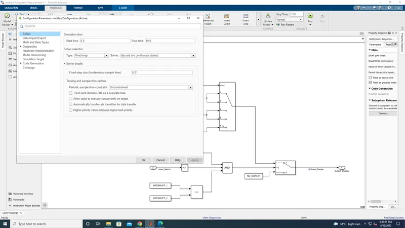
Set sample time as 0.01
And in solver selection as Fixed type and discrete( no continous states)
And click on code generation
and click on browse and select Embeder code and click on ok.
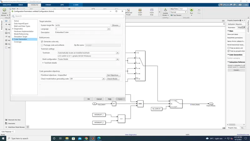
Now need to create as SLDD
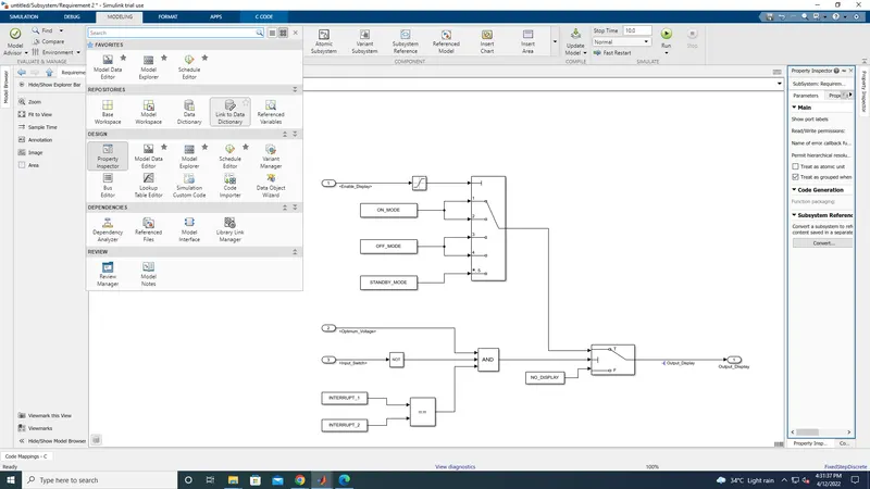
now click on modeling tab and select link to data dictonary
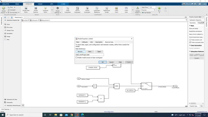
in that new pop up window click on new and create SLDD with the file name
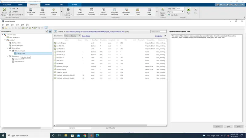
Now the SLDD been creatted and save it.
Now need to check model advisor check for MAB gudline as per the conditions
so Click on modeling tab and select model advisor
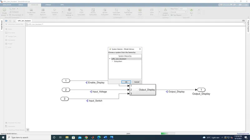
now click on ok, then new tab will be open
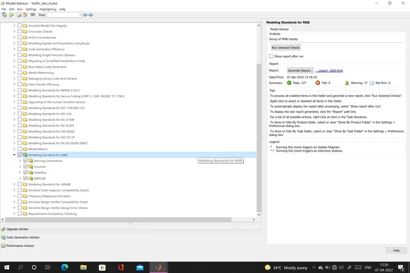
in that need to select Model standard for MAB and run and the result for MAB has been on the above screen
Now MAB guideline has been checked and it been run sucessfully
Now need to generate the C code for this model
For that need to select APPS on the top and select EMBEDED coder
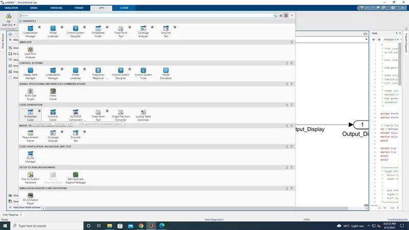
on the top new tab will be open like C code
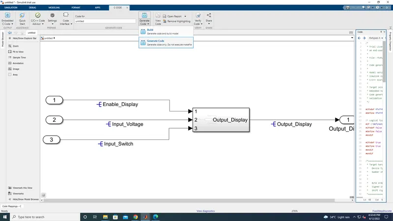
in that need to click on generate code then the c code will be generated
and it will attached below
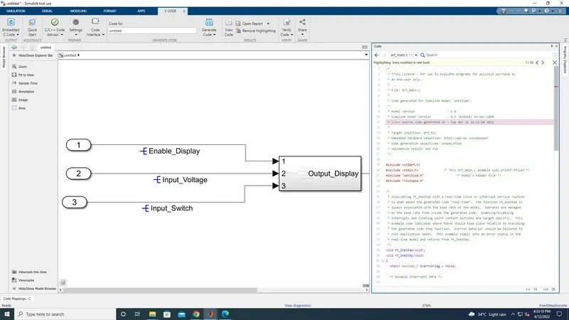
code generation
/*
 * Trial License - for use to evaluate programs for possible purchase as
 * an end-user only.
 *
 * File: ert_main.c
 *
 * Code generated for Simulink model 'untitled'.
 *
 * Model version                  : 1.0
 * Simulink Coder version         : 9.5 (R2021a) 14-Nov-2020
 * C/C++ source code generated on : Tue Apr 12 16:18:38 2022
 *
 * Target selection: ert.tlc
 * Embedded hardware selection: Intel->x86-64 (Windows64)
 * Code generation objectives: Unspecified
 * Validation result: Not run
 */

#include
#include               /* This ert_main.c example uses printf/fflush */
#include "untitled.h"                  /* Model's header file */
#include "rtwtypes.h"

/*
 * Associating rt_OneStep with a real-time clock or interrupt service routine
 * is what makes the generated code "real-time".  The function rt_OneStep is
 * always associated with the base rate of the model.  Subrates are managed
 * by the base rate from inside the generated code.  Enabling/disabling
 * interrupts and floating point context switches are target specific.  This
 * example code indicates where these should take place relative to executing
 * the generated code step function.  Overrun behavior should be tailored to
 * your application needs.  This example simply sets an error status in the
 * real-time model and returns from rt_OneStep.
 */
void rt_OneStep(void);
void rt_OneStep(void)
{
  static boolean_T OverrunFlag = false;

  /* Disable interrupts here */

  /* Check for overrun */
  if (OverrunFlag) {
    rtmSetErrorStatus(untitled_M, "Overrun");
    return;
  }

  OverrunFlag = true;

  /* Save FPU context here (if necessary) */
  /* Re-enable timer or interrupt here */
  /* Set model inputs here */

  /* Step the model */
  untitled_step();

  /* Get model outputs here */

  /* Indicate task complete */
  OverrunFlag = false;

  /* Disable interrupts here */
  /* Restore FPU context here (if necessary) */
  /* Enable interrupts here */
}

/*
 * The example "main" function illustrates what is required by your
 * application code to initialize, execute, and terminate the generated code.
 * Attaching rt_OneStep to a real-time clock is target specific.  This example
 * illustrates how you do this relative to initializing the model.
 */
int_T main(int_T argc, const char *argv[])
{
  /* Unused arguments */
  (void)(argc);
  (void)(argv);

  /* Initialize model */
  untitled_initialize();

  /* Attach rt_OneStep to a timer or interrupt service routine with
   * period 0.01 seconds (the model's base sample time) here.  The
   * call syntax for rt_OneStep is
   *
   *  rt_OneStep();
   */
  printf("Warning: The simulation will run forever. "
         "Generated ERT main won't simulate model step behavior. "
         "To change this behavior select the 'MAT-file logging' option.\n");
  fflush((NULL));
  while (rtmGetErrorStatus(untitled_M) == (NULL)) {
    /*  Perform other application tasks here */
  }

  /* Disable rt_OneStep() here */

  /* Terminate model */
  untitled_terminate();
  return 0;
}

/*
 * File trailer for generated code.
 *
 * [EOF]
 */
/*
* Trial License - for use to evaluate programs for possible purchase as
* an end-user only.
*
* File: untitled.c
*
* Code generated for Simulink model 'untitled'.
*
* Model version : 1.0
* Simulink Coder version : 9.5 (R2021a) 14-Nov-2020
* C/C++ source code generated on : Tue Apr 12 16:18:38 2022
*
* Target selection: ert.tlc
* Embedded hardware selection: Intel->x86-64 (Windows64)
* Code generation objectives: Unspecified
* Validation result: Not run
*/
#include "untitled.h"
#include "untitled_private.h"
/* Real-time model */
static RT_MODEL_untitled_T untitled_M_;
RT_MODEL_untitled_T *const untitled_M = &untitled_M_;
/* Model step function */
void untitled_step(void)
{
uint8_T tmp;
/* Logic: '/AND' incorporates:
* Constant: '/Constant'
* Constant: '/Constant1'
* Inport: '/Inport1'
* RelationalOperator: '/Relational Operator'
* RelationalOperator: '/Relational Operator1'
*/
Optimum_Voltage = ((Input_Voltage >= VOLTAGE_MINIMUM_RANGE) && (Input_Voltage <=
VOLTAGE_MAXIMUM_RANGE));
/* Switch: '/Switch' incorporates:
* Constant: '/Constant3'
* Constant: '/Constant4'
* Inport: '/Inport2'
* Logic: '/AND'
* Logic: '/NOT'
* RelationalOperator: '/Relational Operator'
*/
if (Optimum_Voltage && (!Input_Switch) && (INTERRUPT_1 == INTERRUPT_2)) {
/* Saturate: '/Saturation' incorporates:
* Inport: '/Inport'
*/
if (Enable_Display < 7) {
tmp = Enable_Display;
} else {
tmp = 7U;
}
/* End of Saturate: '/Saturation' */
/* MultiPortSwitch: '/Multiport Switch' */
switch (tmp) {
case 1:
/* Switch: '/Switch' incorporates:
* Constant: '/Constant'
*/
Output_Display = ON_MODE;
break;
case 2:
/* Switch: '/Switch' incorporates:
* Constant: '/Constant'
*/
Output_Display = ON_MODE;
break;
case 3:
/* Switch: '/Switch' incorporates:
* Constant: '/Constant1'
*/
Output_Display = OFF_MODE;
break;
case 4:
/* Switch: '/Switch' incorporates:
* Constant: '/Constant1'
*/
Output_Display = OFF_MODE;
break;
default:
/* Switch: '/Switch' incorporates:
* Constant: '/Constant2'
*/
Output_Display = STANDBY_MODE;
break;
}
/* End of MultiPortSwitch: '/Multiport Switch' */
} else {
/* Switch: '/Switch' incorporates:
* Constant: '/Constant5'
*/
Output_Display = NO_DISPLAY;
}
/* End of Switch: '/Switch' */
}
/* Model initialize function */
void untitled_initialize(void)
{
/* (no initialization code required) */
}
/* Model terminate function */
void untitled_terminate(void)
{
/* (no terminate code required) */
}
/*
* File trailer for generated code.
*
* [EOF]
*/
/*
 * Trial License - for use to evaluate programs for possible purchase as
 * an end-user only.
 *
 * File: untitled.h
 *
 * Code generated for Simulink model 'untitled'.
 *
 * Model version                  : 1.0
 * Simulink Coder version         : 9.5 (R2021a) 14-Nov-2020
 * C/C++ source code generated on : Tue Apr 12 16:18:38 2022
 *
 * Target selection: ert.tlc
 * Embedded hardware selection: Intel->x86-64 (Windows64)
 * Code generation objectives: Unspecified
 * Validation result: Not run
 */

#ifndef RTW_HEADER_untitled_h_
#define RTW_HEADER_untitled_h_
#ifndef untitled_COMMON_INCLUDES_
#define untitled_COMMON_INCLUDES_
#include "rtwtypes.h"
#endif                                 /* untitled_COMMON_INCLUDES_ */

#include "untitled_types.h"

/* Includes for objects with custom storage classes. */
#include "week7_head.h"

/* Macros for accessing real-time model data structure */
#ifndef rtmGetErrorStatus
#define rtmGetErrorStatus(rtm)         ((rtm)->errorStatus)
#endif

#ifndef rtmSetErrorStatus
#define rtmSetErrorStatus(rtm, val)    ((rtm)->errorStatus = (val))
#endif

/* Real-time Model Data Structure */
struct tag_RTM_untitled_T {
  const char_T * volatile errorStatus;
};

/* Model entry point functions */
extern void untitled_initialize(void);
extern void untitled_step(void);
extern void untitled_terminate(void);

/* Real-time Model object */
extern RT_MODEL_untitled_T *const untitled_M;

/*-
 * The generated code includes comments that allow you to trace directly
 * back to the appropriate location in the model.  The basic format
 * is /block_name, where system is the system number (uniquely
 * assigned by Simulink) and block_name is the name of the block.
 *
 * Use the MATLAB hilite_system command to trace the generated code back
 * to the model.  For example,
 *
 * hilite_system('')    - opens system 3
 * hilite_system('/Kp') - opens and selects block Kp which resides in S3
 *
 * Here is the system hierarchy for this model
 *
 * '' : 'untitled'
 * ''   : 'untitled/Subsystem'
 * ''   : 'untitled/Subsystem/Subsystem'
 * ''   : 'untitled/Subsystem/Subsystem1'
 */
#endif                                 /* RTW_HEADER_untitled_h_ */

/*
 * File trailer for generated code.
 *
 * [EOF]
 */
/*
* Trial License - for use to evaluate programs for possible purchase as
* an end-user only.
*
* File: untitled_private.h
*
* Code generated for Simulink model 'untitled'.
*
* Model version : 1.0
* Simulink Coder version : 9.5 (R2021a) 14-Nov-2020
* C/C++ source code generated on : Tue Apr 12 16:18:38 2022
*
* Target selection: ert.tlc
* Embedded hardware selection: Intel->x86-64 (Windows64)
* Code generation objectives: Unspecified
* Validation result: Not run
*/
#ifndef RTW_HEADER_untitled_private_h_
#define RTW_HEADER_untitled_private_h_
#include "rtwtypes.h"
/* Imported (extern) block signals */
extern uint8_T Enable_Display; /* '/Inport' */
extern uint8_T Input_Voltage; /* '/Inport1' */
extern boolean_T Input_Switch; /* '/Inport2' */
#endif /* RTW_HEADER_untitled_private_h_ */
/*
* File trailer for generated code.
*
* [EOF]
*/
/*
 * Trial License - for use to evaluate programs for possible purchase as
 * an end-user only.
 *
 * File: untitled_types.h
 *
 * Code generated for Simulink model 'untitled'.
 *
 * Model version                  : 1.0
 * Simulink Coder version         : 9.5 (R2021a) 14-Nov-2020
 * C/C++ source code generated on : Tue Apr 12 16:18:38 2022
 *
 * Target selection: ert.tlc
 * Embedded hardware selection: Intel->x86-64 (Windows64)
 * Code generation objectives: Unspecified
 * Validation result: Not run
 */

#ifndef RTW_HEADER_untitled_types_h_
#define RTW_HEADER_untitled_types_h_

/* Model Code Variants */

/* Forward declaration for rtModel */
typedef struct tag_RTM_untitled_T RT_MODEL_untitled_T;

#endif                                 /* RTW_HEADER_untitled_types_h_ */

/*
 * File trailer for generated code.
 *
 * [EOF]
 */
/*
 * Trial License - for use to evaluate programs for possible purchase as
 * an end-user only.
 *
 * File: week7_def.c
 *
 * Code generated for Simulink model 'untitled'.
 *
 * Model version                  : 1.0
 * Simulink Coder version         : 9.5 (R2021a) 14-Nov-2020
 * C/C++ source code generated on : Tue Apr 12 16:18:38 2022
 *
 * Target selection: ert.tlc
 * Embedded hardware selection: Intel->x86-64 (Windows64)
 * Code generation objectives: Unspecified
 * Validation result: Not run
 */

#include "rtwtypes.h"
#include "untitled_types.h"

/* Exported data definition */

/* Definition for custom storage class: ExportToFile */
boolean_T Optimum_Voltage;             /* '/AND' */
uint8_T Output_Display;                /* '/Switch' */

/* Const memory section */
/* Definition for custom storage class: Const */
const boolean_T INTERRUPT_1 = 1;       /* Referenced by: '/Constant3' */
const boolean_T INTERRUPT_2 = 1;       /* Referenced by: '/Constant4' */
const uint8_T NO_DISPLAY = 0U;         /* Referenced by: '/Constant5' */
const uint8_T OFF_MODE = 2U;           /* Referenced by: '/Constant1' */
const uint8_T ON_MODE = 1U;            /* Referenced by: '/Constant' */
const uint8_T STANDBY_MODE = 3U;       /* Referenced by: '/Constant2' */
const uint8_T VOLTAGE_MAXIMUM_RANGE = 50U;/* Referenced by: '/Constant1' */
const uint8_T VOLTAGE_MINIMUM_RANGE = 30U;/* Referenced by: '/Constant' */

/*
 * File trailer for generated code.
 *
 * [EOF]
 */
/*
* Trial License - for use to evaluate programs for possible purchase as
* an end-user only.
*
* File: week7_head.h
*
* Code generated for Simulink model 'untitled'.
*
* Model version : 1.0
* Simulink Coder version : 9.5 (R2021a) 14-Nov-2020
* C/C++ source code generated on : Tue Apr 12 16:18:38 2022
*
* Target selection: ert.tlc
* Embedded hardware selection: Intel->x86-64 (Windows64)
* Code generation objectives: Unspecified
* Validation result: Not run
*/
#ifndef RTW_HEADER_week7_head_h_
#define RTW_HEADER_week7_head_h_
#include "rtwtypes.h"
#include "untitled_types.h"
/* Exported data declaration */
/* Declaration for custom storage class: ExportToFile */
extern boolean_T Optimum_Voltage; /* '/AND' */
extern uint8_T Output_Display; /* '/Switch' */
/* Const memory section */
/* Declaration for custom storage class: Const */
extern const boolean_T INTERRUPT_1; /* Referenced by: '/Constant3' */
extern const boolean_T INTERRUPT_2; /* Referenced by: '/Constant4' */
extern const uint8_T NO_DISPLAY; /* Referenced by: '/Constant5' */
extern const uint8_T OFF_MODE; /* Referenced by: '/Constant1' */
extern const uint8_T ON_MODE; /* Referenced by: '/Constant' */
extern const uint8_T STANDBY_MODE; /* Referenced by: '/Constant2' */
extern const uint8_T VOLTAGE_MAXIMUM_RANGE;/* Referenced by: '/Constant1' */
extern const uint8_T VOLTAGE_MINIMUM_RANGE;/* Referenced by: '/Constant' */
#endif /* RTW_HEADER_week7_head_h_ */
/*
* File trailer for generated code.
*
* [EOF]
*/
/*
 * Trial License - for use to evaluate programs for possible purchase as
 * an end-user only.
 *
 * File: rtwtypes.h
 *
 * Code generated for Simulink model 'untitled'.
 *
 * Model version                  : 1.0
 * Simulink Coder version         : 9.5 (R2021a) 14-Nov-2020
 * C/C++ source code generated on : Tue Apr 12 16:18:38 2022
 *
 * Target selection: ert.tlc
 * Embedded hardware selection: Intel->x86-64 (Windows64)
 * Code generation objectives: Unspecified
 * Validation result: Not run
 */

#ifndef RTWTYPES_H
#define RTWTYPES_H

/* Logical type definitions */
#if (!defined(__cplusplus))
#ifndef false
#define false                          (0U)
#endif

#ifndef true
#define true                           (1U)
#endif
#endif

/*=======================================================================*
 * Target hardware information
 *   Device type: Intel->x86-64 (Windows64)
 *   Number of bits:     char:   8    short:   16    int:  32
 *                       long:  32
 *                       native word size:  64
 *   Byte ordering: LittleEndian
 *   Signed integer division rounds to: Zero
 *   Shift right on a signed integer as arithmetic shift: on
 *=======================================================================*/

/*=======================================================================*
 * Fixed width word size data types:                                     *
 *   int8_T, int16_T, int32_T     - signed 8, 16, or 32 bit integers     *
 *   uint8_T, uint16_T, uint32_T  - unsigned 8, 16, or 32 bit integers   *
 *   real32_T, real64_T           - 32 and 64 bit floating point numbers *
 *=======================================================================*/
typedef signed char int8_T;
typedef unsigned char uint8_T;
typedef short int16_T;
typedef unsigned short uint16_T;
typedef int int32_T;
typedef unsigned int uint32_T;
typedef float real32_T;
typedef double real64_T;

/*===========================================================================*
 * Generic type definitions: boolean_T, char_T, byte_T, int_T, uint_T,       *
 *                           real_T, time_T, ulong_T.                        *
 *===========================================================================*/
typedef double real_T;
typedef double time_T;
typedef unsigned char boolean_T;
typedef int int_T;
typedef unsigned int uint_T;
typedef unsigned long ulong_T;
typedef char char_T;
typedef unsigned char uchar_T;
typedef char_T byte_T;

/*===========================================================================*
 * Complex number type definitions                                           *
 *===========================================================================*/
#define CREAL_T

typedef struct {
  real32_T re;
  real32_T im;
} creal32_T;

typedef struct {
  real64_T re;
  real64_T im;
} creal64_T;

typedef struct {
  real_T re;
  real_T im;
} creal_T;

#define CINT8_T

typedef struct {
  int8_T re;
  int8_T im;
} cint8_T;

#define CUINT8_T

typedef struct {
  uint8_T re;
  uint8_T im;
} cuint8_T;

#define CINT16_T

typedef struct {
  int16_T re;
  int16_T im;
} cint16_T;

#define CUINT16_T

typedef struct {
  uint16_T re;
  uint16_T im;
} cuint16_T;

#define CINT32_T

typedef struct {
  int32_T re;
  int32_T im;
} cint32_T;

#define CUINT32_T

typedef struct {
  uint32_T re;
  uint32_T im;
} cuint32_T;

/*=======================================================================*
 * Min and Max:                                                          *
 *   int8_T, int16_T, int32_T     - signed 8, 16, or 32 bit integers     *
 *   uint8_T, uint16_T, uint32_T  - unsigned 8, 16, or 32 bit integers   *
 *=======================================================================*/
#define MAX_int8_T                     ((int8_T)(127))
#define MIN_int8_T                     ((int8_T)(-128))
#define MAX_uint8_T                    ((uint8_T)(255U))
#define MAX_int16_T                    ((int16_T)(32767))
#define MIN_int16_T                    ((int16_T)(-32768))
#define MAX_uint16_T                   ((uint16_T)(65535U))
#define MAX_int32_T                    ((int32_T)(2147483647))
#define MIN_int32_T                    ((int32_T)(-2147483647-1))
#define MAX_uint32_T                   ((uint32_T)(0xFFFFFFFFU))

/* Block D-Work pointer type */
typedef void * pointer_T;

#endif                                 /* RTWTYPES_H */

/*
 * File trailer for generated code.
 *
 * [EOF]
 */