Project 1 - Review of Shear & Moment Connections in RAM Connection
Q Design and optimize typical shear, moment and Splice joints in RAM Connection for the following structure modelled in Staad Pro. Design and optimize base plate connection.
Structure: A 2D portal frame fixed support spanning 15m with a pitched roof ridge height of 12m, slope of 4 degrees. A uniformly distributed load of 10kN/m is applied on the roof beams. Optimize the beams and columns for 85% utilization and consider splice joints at 6m from base and 4m from beam column joints. Consider a hanger beam shear connected with column support of 4m height from the splice joint with a length of 3m from beam-column corner joint carrying 5kN/m load. Use hot rolled sections.
AIM & INTRODUCTION:
Shear, moment and Splice joints in RAM Connection for a 2D portal frame is required to be designed with following inputs/data-
Inputs :
Supports o 2D Frame : Fixed support
Spann : 15m
Roof : Pitched roof
Ridge height : 12m
Slope : 4 degrees
Load : UDL of 10 kN/m on roof beam
Stees Section : Hot rolled
Splice joint location : At 6 m from base
Hanger beam : Shear connected with column support of 4 m height from splice joint with
a length of 3m with a beam column corner joint carrying 5 kN/m load
Also Design and optimize base plate connection. Optimise beam and column for 85% utilization
PROCEDURE IN DETAIL-
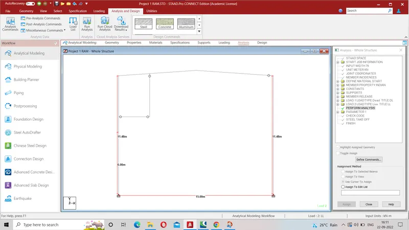
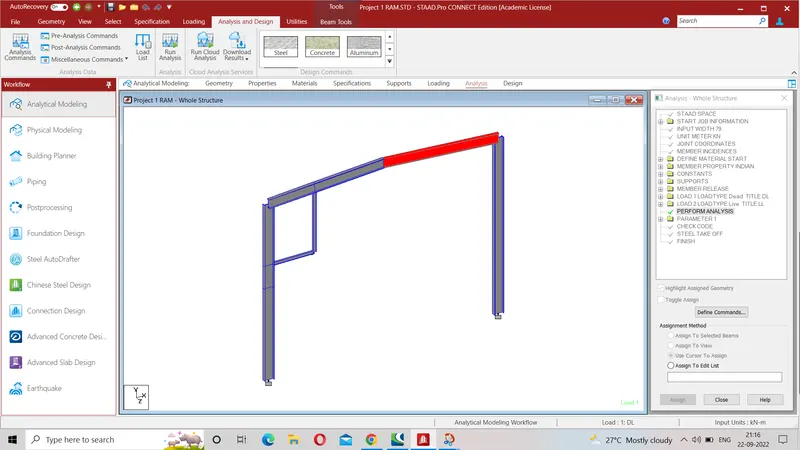
1- 2D portal frame as per given data and loading is shown below-
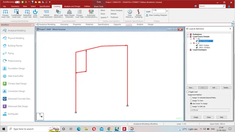
2 (i)- Self weight in the form of Dead load is assigned as shown below-
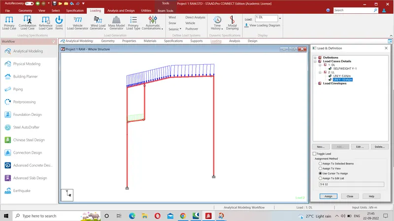
2 (ii)- Live load of 10 Kn/m as UDL on roof beam is assigned as shown below-
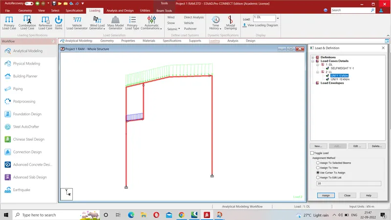
2 (iii)- Live load of 5 Kn/m as UDL on hanger beam is assigned as shown below-
3D view of 2D portal frame-
3- Shear, moment and splice joints are created as shown below-
# Bolted splice flange plate joint is between member 1 & 8 at node 7
# Beam column flange bolted moment joint is between member 5 & 9 at node 3
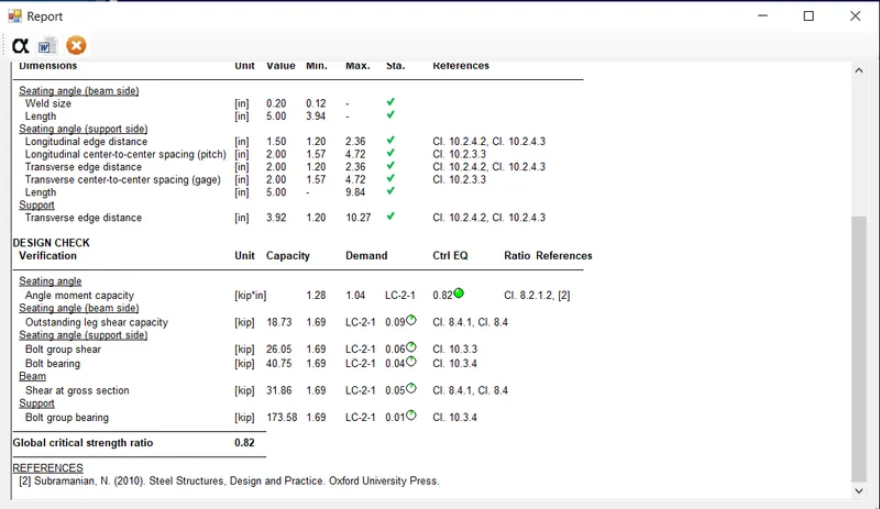
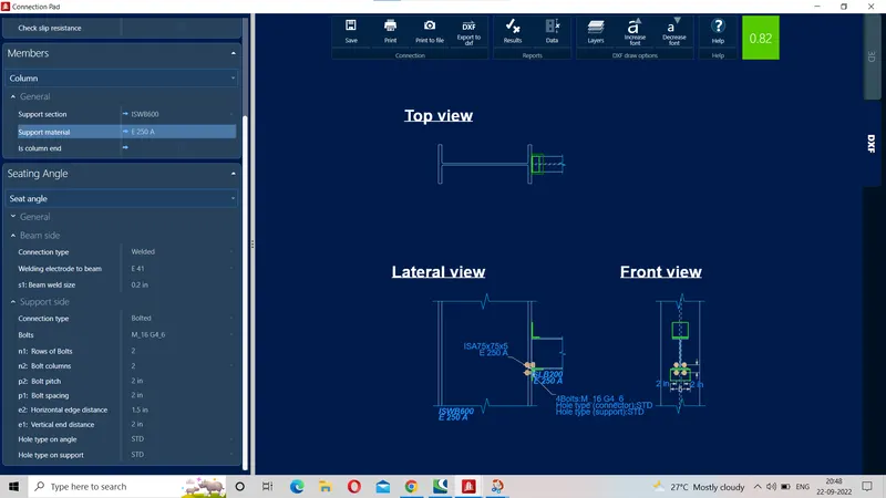
# Beam column flange seating angle shear connection at node 8 between member 9 &10
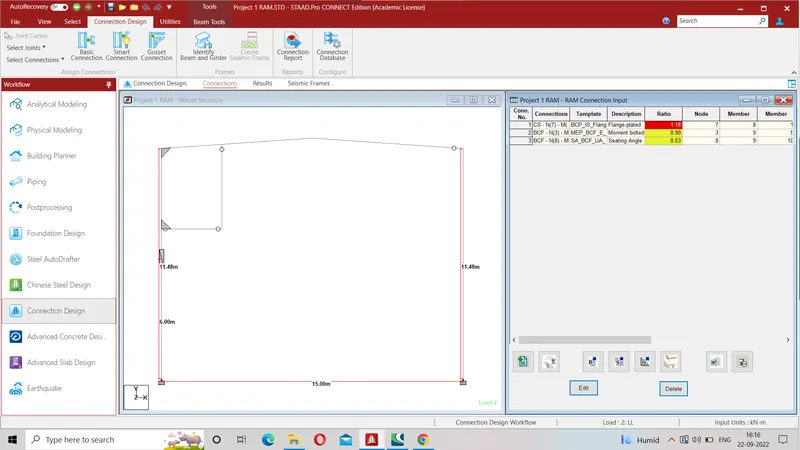
Above steps up to step-3 are common to all the joints so shall not be repeated
Design of 1st joint
4-Bolted splice flange plate joint is between member 1 & 8 at node 7
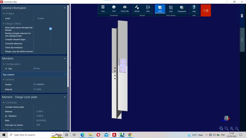
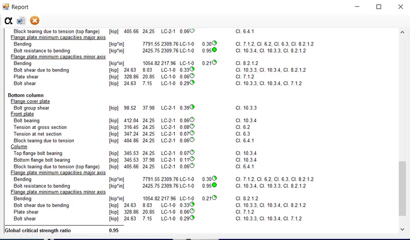
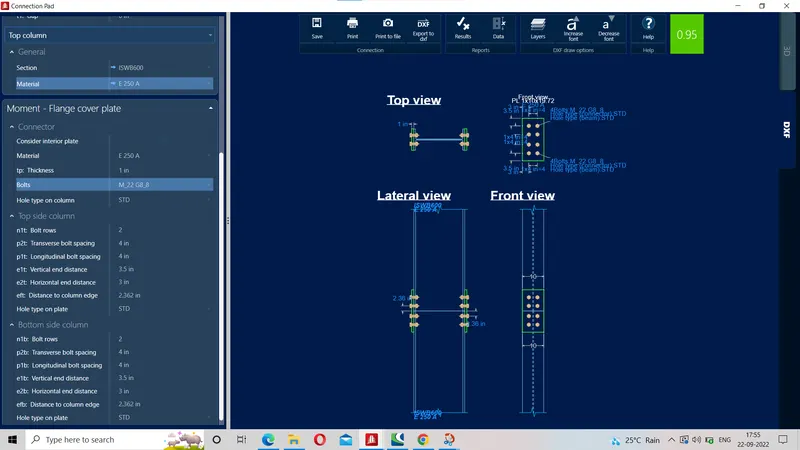
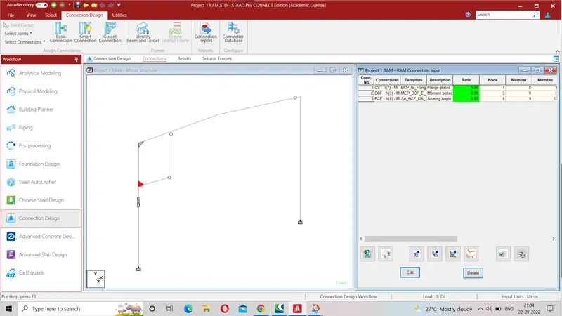
5- Design of Bolted splice flange plate joint is designed as shown below in which utolisation ratio is 0.95 < 1.0
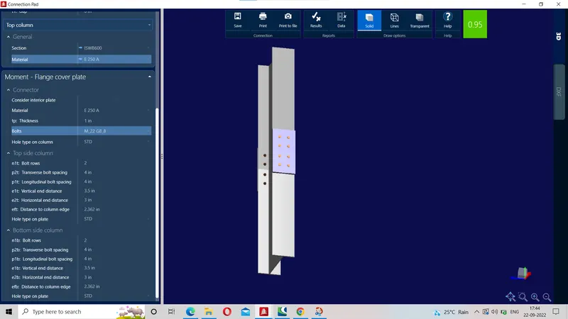
6- Report- Data
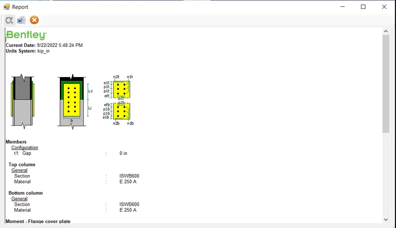
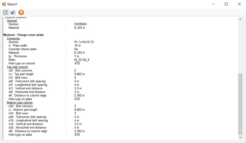
7-Report- Results
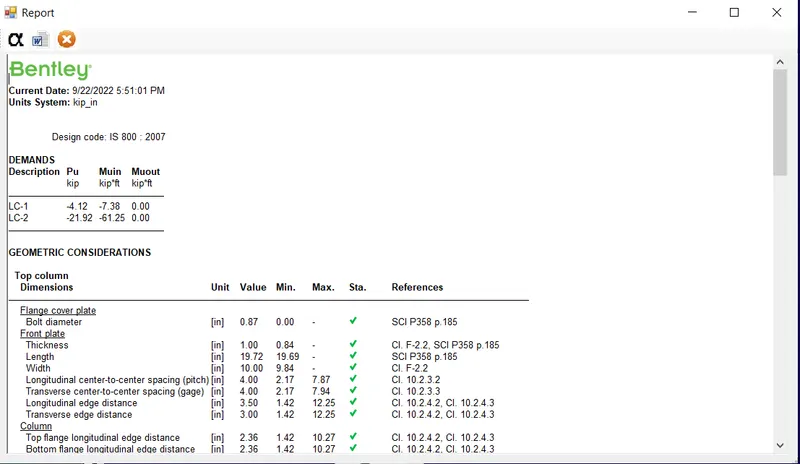
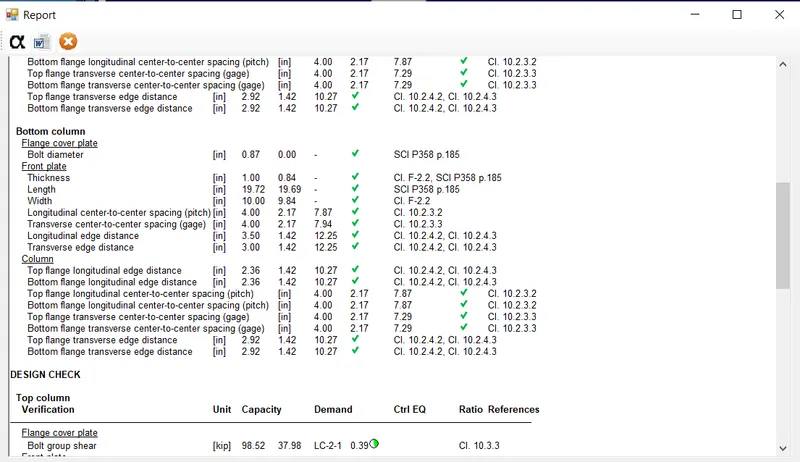
8- DXF details-
------------- xxxxxx------------------ END OF 1ST JOINT-------------------XXXXXXXXXXXX----------------------------------------
Design of 2nd joint
# 1- Beam column flange bolted moment joint is between member 5 & 9 at node 3
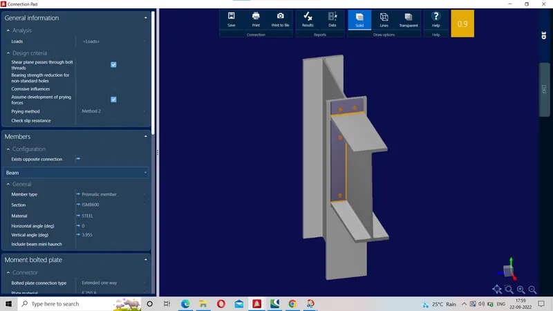
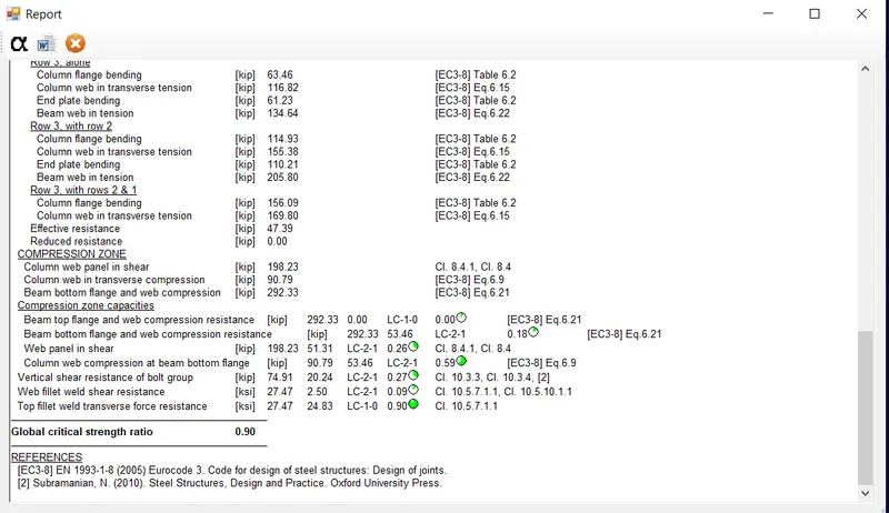
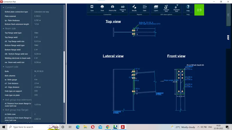
2-Design of Beam column flange bolted moment joint is between member 5 & 9 at node 3 is as shown below in which utilisation ratio is 0.9 <1.0 ( safe)
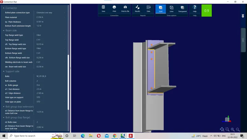
3-Report- Data
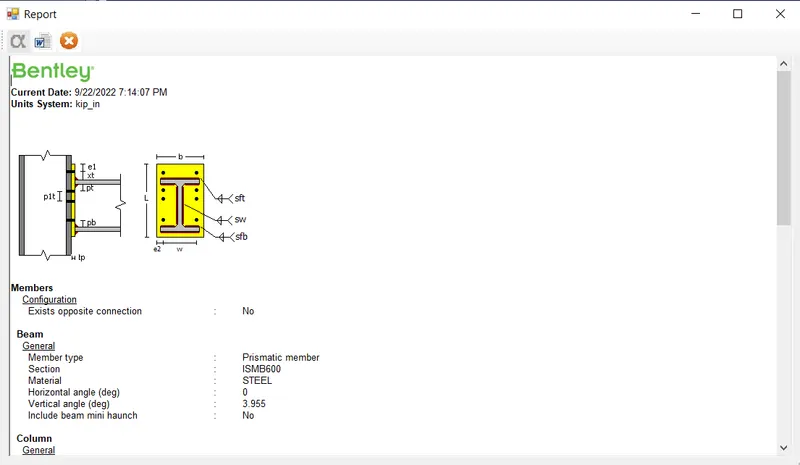
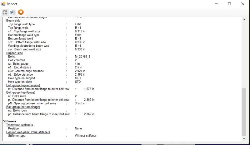
4- Report- Results
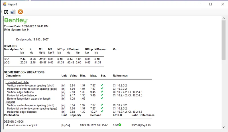
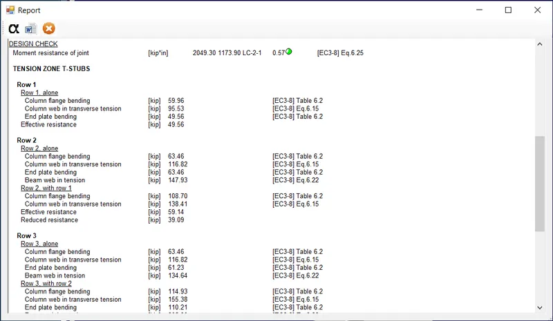
5- DXF details-
----------------xxxxxxx----------------- END OF 2nd Joint-----------xxxxxxxx--------xxxxxxxxxxxxxxxxx--------
Design of 3rd joint
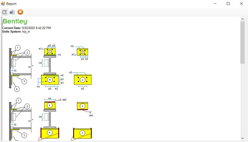
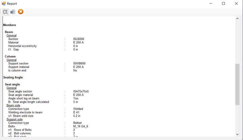
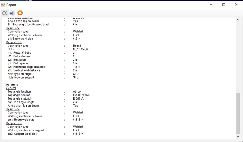
# 1-Beam column flange seating angle shear connection at node 8 between member 9 &10
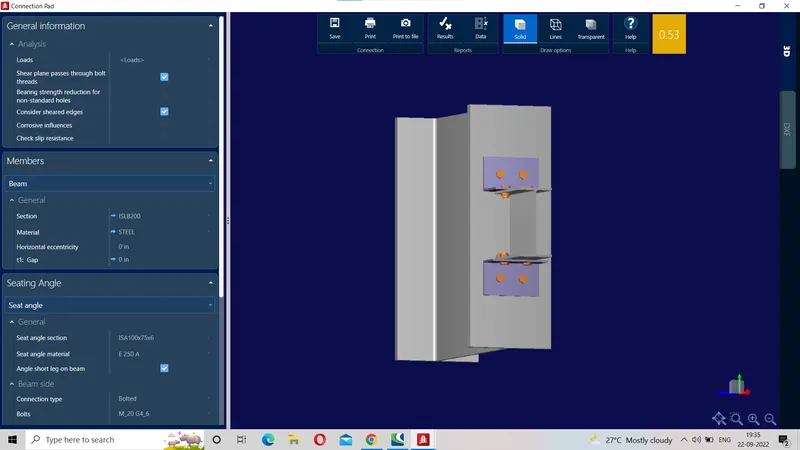
2-Design of Beam column flange seating angle shear connection at node 8 between member 9 &10
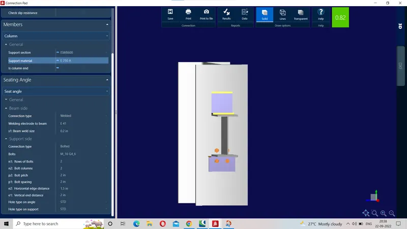
3-Report- Data
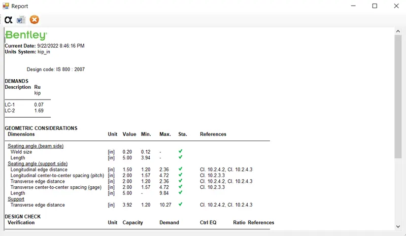
4-Report- Results-
5-DXF Details-
--------------------xxxxxxxxxxx------------ End of 3rd joint--------------------xxxxxxxx------------xx--------------------
RESULT - Thus 2D Portal frame is created in staad pro with given data and typical shear, moment and slice joint in RAM connection for 2D portal frame are designed and optimized as shown below. Design of all the 03 joints are safe from Geometrical consideration as well as on strength criteria as indicated from utilization ratio which are 0.95 , 0.9 and 0.82 very close to 1.0 but < 1.0
-----------------xxxxxxxxxxxxx------------- END OF SOLUTION TOCHALLENGE--------------XXXXXXXXX--------------