Project-1: Powertrain for aircraft in runways
Questions:
- list out the total weight of various types of aircrafts.
- Difference between ground speed and air speed.
- Why is it not recomeended to use aircraft engine power to move it on the ground at airport?
- How an air craft is pushed to runway when its ready to take off?
- Learn about take off power, tyre design, rolling resistance, tyre pressure, brake forces when landing.
- With necessary assumptions, calculate the force and power required to push / pull an aircraft by a towing vehicle.
- Design an electric powertrain with type of motor, it’s power rating, and energy requirement to fulfill aircraft towing application. Estimate the duty cycle range to control the aircraft speed from zero to highest. Make all required assumptions. Prepare a table of assumed parameters. Draw a block diagram of powertrain.
Answers:
1.
Maximum design taxi weight (MDTW)
The maximum design taxi weight (also known as the maximum design ramp weight (MDRW)) is the maximum weight certificated for aircraft manoeuvring on the ground (taxiing or towing) as limited by aircraft strength and airworthiness requirements.
Maximum design takeoff weight (MDTOW)
Is the maximum certificated design weight when the brakes are released for takeoff and is the greatest weight for which compliance with the relevant structural and engineering requirements has been demonstrated by the manufacturer.
Maximum design landing weight (MDLW)
The maximum certificated design weight at which the aircraft meets the appropriate landing certification requirements. It generally depends on the landing gear strength or the landing impact loads on certain parts of the wing structure.
The MDLW must not exceed the MDTOW.
The maximum landing weight is typically designed for 10 feet per second (600 feet per minute) sink rate at touch down with no structural damage.
Maximum design zero-fuel weight (MDZFW)
The maximum certificated design weight of the aircraft less all usable fuel and other specified usable agents (engine injection fluid, and other consumable propulsion agents). It is the maximum weight permitted before usable fuel and other specified usable fluids are loaded in specified sections of the airplane. The MDZFW is limited by strength and airworthiness requirements. At this weight, the subsequent addition of fuel will not result in the aircraft design strength being exceeded. The weight difference between the MDTOW and the MDZFW may be utilised only for the addition of fuel.
Minimum flight weight (MFW)
Minimum certificated weight for flight as limited by aircraft strength and airworthiness requirements.
2.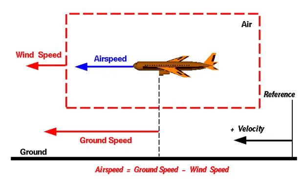
Wind Speed
For a reference point picked on the ground, the air moves relative to the reference point at the wind speed. Notice that the wind speed is a vector quantity and has both a magnitude and a direction. Direction is important. A 20 mph wind from the west is different from a 20 mph wind from the east. The wind has components in all three primary directions (north-south, east-west, and up-down). In this figure, we are considering only velocities along the aircraft's flight path. A positive velocity is defined to be in the direction of the aircraft's motion. We are neglecting cross winds, which occur perpendicular to the flight path but parallel to the ground, and updrafts and downdrafts, which occur perpendicular to the ground.
Ground Speed
For a reference point picked on the ground, the aircraft moves relative to the reference point at the ground speed. Ground speed is also a vector quantity so a comparison of the ground speed to the wind speed must be done according to rules for vector comparisons.
Airspeed
The important quantity in the generation of lift is the relative velocity between the object and the air, which is called the airspeed. Airspeed cannot be directly measured from a ground position, but must be computed from the ground speed and the wind speed. Airspeed is the vector difference between the ground speed and the wind speed.
Airspeed = Ground Speed - Wind Speed
On a perfectly still day, the airspeed is equal to the ground speed. But if the wind is blowing in the same direction that the aircraft is moving, the airspeed will be less than the ground speed.
- It is not recommended to use aircraft engine power to move it on the ground at airport because there are certain extreme cautions for everything around us like
- Applying thrust(gas) can create a blast behind each engine.
- People, equipment and anything else in the way can be injured or damaged from the jet blast.
- Before we apply power to the engines the areas in front of a each engine are like another super critical factor that must be carefully negotiated.
- The immediate area in front of a jet engine creates an area where people and equipment can be sucked in to the engine if anything is too close to the intake.
- So to avoid all such extreme cautions it is not recommended to use aircraft engine power to move it on the ground at the airport.
4.
Pushback is when an aircraft is pushed backwards away from the airport gate by vehicles called tugs or tractors.
Closer to departure, an aircraft tug will park right in front of the nose wheel.
The tug might be directly attached to the plane’s nose gear with a tow bar, or could be a wheel-lift tug. These tugs cradle the nose gear, then lift it up before moving the plane. That gives the tug driver control over the plane’s direction during pushback.
New taxi technologies are appearing, like pilot-controlled tugs and electric motors mounted to the plane’s landing gear. Both promise to save fuel and reduce airport noise.
In such way an aircraft is pushed to runway when it is ready to take off.
5.
Take off power:
The amount of power that an engine is allowed to produce for a limited period of time for takeoff. The use of takeoff power is usually limited to 5 min for reciprocating engines and up to 2½ min for gas turbine engines. This may not always be the case.
Tyre design:
An aircraft tire or tyre is designed to withstand extremely heavy loads for short durations.[1] The number of tires required for aircraft increases with the weight of the aircraft, as the weight of the airplane needs to be distributed more evenly. Aircraft tire tread patterns are designed to facilitate stability in high crosswind conditions, to channel water away to prevent hydroplaning, and for braking effect.
Aircraft tires also include fusible plugs (which are assembled on the inside of the wheels), designed to melt at a certain temperature. Tires often overheat if maximum braking is applied during an aborted takeoff or an emergency landing. The fuses provide a safer failure mode that prevents tire explosions by deflating in a controlled manner, thus minimizing damage to aircraft and objects in the surrounding environment.
Design and construction of aircraft tool:
Carcass plies are used to form the tire. They are sometimes called casing plies. An aircraft tyre is constructed for the purpose it serves.
- They support the weight of an aircraft while it is on the ground.
- It also provides the necessary traction for braking and stopping of an aeroplane.
- Tyre also helps to absorb the shock of landing and provide cushioning the roughness of takeoff, roll-out, and taxi operations.
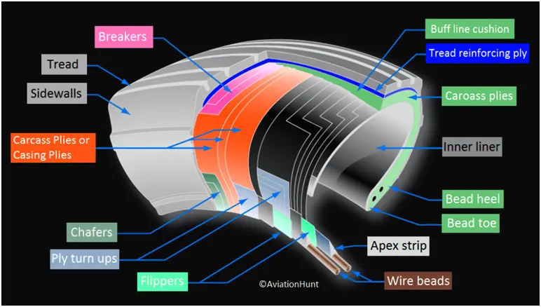
Let’s go through some technical aspects of the tyre.
Retreading – Retreading is methods of restoring a worn tyre by renewing the tread area or by renewing the tread area plus one or both sidewalls. Repairs are included in the tyre retreading process.
Load Rating – Load rating is the maximum permissible load at a specified inflation pressure.
Ply Rating – Ply Rating is used to identify the maximum recommended load rating and inflation pressure for a specified tyre. It is an index of tyre strength.
Speed Rating – The speed rating is the maximum takeoff speed to which the tyre has been tested.
Skid Depth – Skid depth is the distance between the tread surface and the deepest groove as measured in the mould.
Aircraft tyres must have an approved speed and load rating and have sufficient clearance when retracted through landing gear to allow for tyre growth. Tyre growth is the increase in the size of the tyre due to centrifugal forces at high speed.
Aircraft tyres may be Tube-type or Tubeless
Tubeless tyres are more advantageous over tube-type. There is no longer the use of tube-type tyre in recent aviation. Nowadays all airliners are using tubeless tyres. Tubeless that are meant to be used without a tube has the word TUBELESS on the sidewall of the tyre.
Aircraft tyres may be Radial or Bias
Almost all airliners are using Radial tyre. Bias is an older design, and it’s mainly used for road vehicles. Radial tyres have the word RADIAL on the sidewall. Radial tires are more expensive than bias-ply tyres. Radial tires are in demand because of their lower life cycle cost and long term value.
Rolling resistance:
Rolling resistance, sometimes called rolling friction or rolling drag, is the force resisting the motion when a body (such as a ball, tire, or wheel) rolls on a surface. It is mainly caused by non-elastic effects; that is, not all the energy needed for deformation (or movement) of the wheel, roadbed, etc., is recovered when the pressure is removed. Two forms of this are hysteresis losses and permanent (plastic) deformation of the object or the surface (e.g. soil). Another cause of rolling resistance lies in the slippage between the wheel and the surface, which dissipates energy. Note that only the last of these effects involves friction, therefore the name "rolling friction" is to an extent a misnomer.
In analogy with sliding friction, rolling resistance is often expressed as a coefficient times the normal force. This coefficient of rolling resistance is generally much smaller than the coefficient of sliding friction.
Any coasting wheeled vehicle will gradually slow down due to rolling resistance including that of the bearings, but a train car with steel wheels running on steel rails will roll farther than a bus of the same mass with rubber tires running on tarmac. Factors that contribute to rolling resistance are the (amount of) deformation of the wheels, the deformation of the roadbed surface, and movement below the surface. Additional contributing factors include wheel diameter, load on wheel, surface adhesion, sliding, and relative micro-sliding between the surfaces of contact. The losses due to hysteresis also depend strongly on the material properties of the wheel or tire and the surface. For example, a rubber tire will have higher rolling resistance on a paved road than a steel railroad wheel on a steel rail. Also, sand on the ground will give more rolling resistance than concrete. Sole rolling resistance factor is not dependent on speed.
Tyre pressure:
Aircraft tires generally operate at high pressures, up to 200 psi (14 bar; 1,400 kPa) for airliners, and even higher for business jets. The main landing gear on the Concorde was typically inflated to 232 psi (16.0 bar), whilst its tail bumper gear tires were as high as 294 psi (20.3 bar).The high pressure and weight load on the Concorde tyres were a significant factor
Tests of airliner aircraft tires have shown that they are able to sustain pressures of maximum 800 psi (55 bar; 5,500 kPa) before bursting. During the tests the tires have to be filled with water, to prevent the test room being blown apart by the energy that would be released by a gas when the tire bursts.
Aircraft tires are usually inflated with nitrogen to minimize expansion and contraction from extreme changes in ambient temperature and pressure experienced during flight.Dry nitrogen expands at the same rate as other dry atmospheric gases (normal air is about 80% nitrogen), but common compressed air sources may contain moisture, which increases the expansion rate with temperature.
The requirement that an inert gas, such as nitrogen, be used instead of air for inflation of tires on certain transport category airplanes was prompted by at least three cases in which the oxygen in air-filled tires had combined with volatile gases given off by a severely overheated tire and exploded upon reaching autoignition temperature. The use of an inert gas for tire inflation eliminates the possibility of tire explosion.
Braking force:
Aircraft disc brakes in the landing gear, used to brake the wheels while touching the ground. These brakes are operated hydraulically or pneumatically. In most modern aircraft they are activated by the top section of the rudder pedals ("toe brakes"). In some older aircraft the bottom section is used instead ("heel brakes"). Levers are used in a few aircraft. Most aircraft are capable of differential braking.
Thrust reversers, that allow thrust from the engines to be used to slow the aircraft.
Air brakes, dedicated flight control surfaces that work by increasing drag.
Large drogue parachutes, used by several former and current military and civilian aircraft (examples include the American B-52 and the soviet Tu-134 and Tu-144) and in the Space Shuttle.
6.
Here the pushback trucks experience two kinds of forces acting on them when they ry to push/pull the aircraft.
1)Rolling reisitance force
2) Aerodynamic drag force
Rolling resistance force- The formula used for the rolling resistance force is mentioned below,
Frr=u*m*g
Where,
u is the coefficient of rolling resisitance, m is the mass and g is the acceleration due to gravity.
This rolling resistance force acts on both the pushback truck and the aircraft.
So first considering the aircraft, u=0.02, m =40000 kg
Frr =0.02*40000*9.81= 7848N
And now considering for the pushback truck, u=0.09, m=1000 kg
Frr(pushback truck)=0.09*1000*9.81 =883 N
Therefore the total resistance will be the sum of the aircraft & pushback truck rolling resistance =7848+883 =8731 N
Aerodynamic force- The aerodynamic force to move an airplane on an absolute flat runway with no wind at constant low speed is usually very negligible.
Fd=1/2*𝞺*A*Cd*v^2
Where ‘p’ is the ai density kg/m^3
A is the front area in m^2, Cd is the drag co efficient and v is the velocity in m/s.
Since the aerodynamic force is very negligible here, the net force acting on the pushback truck during the push/pull of an aircraft,
Fnet = Frr(pushback)+Frr(aircraft)=8731 N
The power required is,
P=F*V, V is the velocity in m/s by which pushback truck either pushes or pulls the aircraft
P=8731*9.72 =84.86 KW
7.
As we discussed above an aeroplane pushback vehicle is required to move aeroplanes away from airport terminals. Powertrain is a system which covers all the drive train components which propels the vehicle in the road. Here an all wheel drive EV pushback vehicle is considered by using in-wheel motors in each wheel of vehicle better wheel propulsion cab be achieved, ensuring increase of efficiency and better power saving of the whole system. This approach adds to controllability of each individual wheel and decreasing weight of chassis. By proper control of each wheel, it is possible to achieve a better acceleration, torque control and regenerative braking. Implementation of antilock braking system, collision avoidance system, by-wire steering and better overall dynamic stability control are much simpler using four inwheel motors. The pushback vehicle must be able to generate a large towing tractive force, but also have a relatively high top speed to travel quickly between pushback operatins(~30 kph unloaded).
The block diagram of the EV drive train
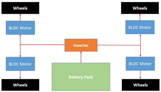
For tow & maintenance the motor requires high torque and low speed and for carrying the solo motor requires low torque and high speed. In the question it is mentioned as electric pushback truck, so following are the main components that we are going to discuss about
i)Battery
ii)Power converter
Battery : For the EV to be truly comparable to the ICE counterpart, the SOE of the battery pack should be full at the end of the duty cycle. This would be similar to the ICE vehicle having its fuel tank fillied at the end of a working day traction battery voltage should reflect the best design for duty cycle, vehicle speed, tractive effort, and minimum current losses.
Traction motor: Normally the pushback vehicle would not be held to conventional passenger vehicle development critertia,i.e. fast O-60mph acceleration times or to be able to reach motorway cruising speeds. This is because aeroplane manufactures impose low acceleration limits for towing operations to prevent damage to the landing gear and there are speed limits enforced on working airfields for ground support vehicles.
Here I’m considering the BLDC motor because of better torque- speed characteristics, higher efficiency, high output power to size ratio(due to absence of windings on rotor), higher dynamic response(due to low inertia of rotor),higher operating life, lower maintenance because of absence of brushes, noiseless operation and higher speed ranges are immediate advantages of BLDC motors over brushed DC and induction motor. Higher output power to size ratio of BLDC makes it suitable for EV applications, where space and weight are significant considerations and less maintenance is obligatory. Noiseless operation of BLDC motor also makes it more convenient to have integral motor of BLDC.
Assumed Duty Cycle for the Pushback Vehicle:
An aero plane pushback vehicle is required to move aero planes away from airport terminals and occasionally tow them across an airfield for routine maintenance. Therefore ,the pushback vehicle must be able to generate a large towing force, but also have a relatively high top speed to travel quickly ,between pushback operations.
Assumed vehicle parameters:
Vehicle mass(kg) -16000
Coefficient of Drag -0.8
Frontal area(m^2) -6.8
Wheel radius(m) -0.575
Coefficient of rolling -2
Max brake force(N) -800
Air density(kg/m^3) -1.22
Wheel inertia(kg/m^2) -2.4
From the above the assumed data we can figure out the maximum power and torque needed for the pushback vehicle.
The maximum traction force= Rolling resistance force + Aerodynamic force+ brake force.
Rolling resistance force, Frr=u*m*g=2*16000*9.81=313920
Aerodynamic forceAd=Fd=1/2*𝞺*A*Cd*v*v=0.5*0.8*6.8*1.22*4*4
=53.1(assumed values)
Total force=313920+53.1+800=314773 N
Power
force*velocity=314773*4=1259kW
Maximum torque on wheels=0.575*314773=180kNm