Project-1: Powertrain for aircraft in runways
POWERTRAIN FOR AIRCRAFTS IN RUNWAYS
AIM :
- Search and list out the total weight of various types of aircrafts.
- Is there any difference between ground speed and air speed?
- Why is it not recommended to use aircraft engine power to move it on the ground at Airport?
- How an aircraft is pushed to runway when its ready to take off?
- Learn about take off power, tyre design, rolling resistance, tyre pressure, brake forces when landing.
- With necessary assumptions, calculate the force and power required to push / pull an aircraft by a towing vehicle.
7. Design an electric powertrain with type of motor, it’s power rating, and energy requirement to fulfill aircraft towing application. Estimate the duty cycle range to control the aircraft speed from zero to highest. Make all required assumptions. Prepare a table of assumed parameters. Draw a block diagram of powertrain.
QUESTION 1:
Search and list out the total weight of various types of aircrafts?
EXPLAINATION :
AIRCRAFT :
An aircraft is a vehicle that is able to fly by gaining support from the air. It counters the force of gravity by using either static lift or by using the dynamic lift of an airfoil, or in a few cases the downward thrust from jet engines.
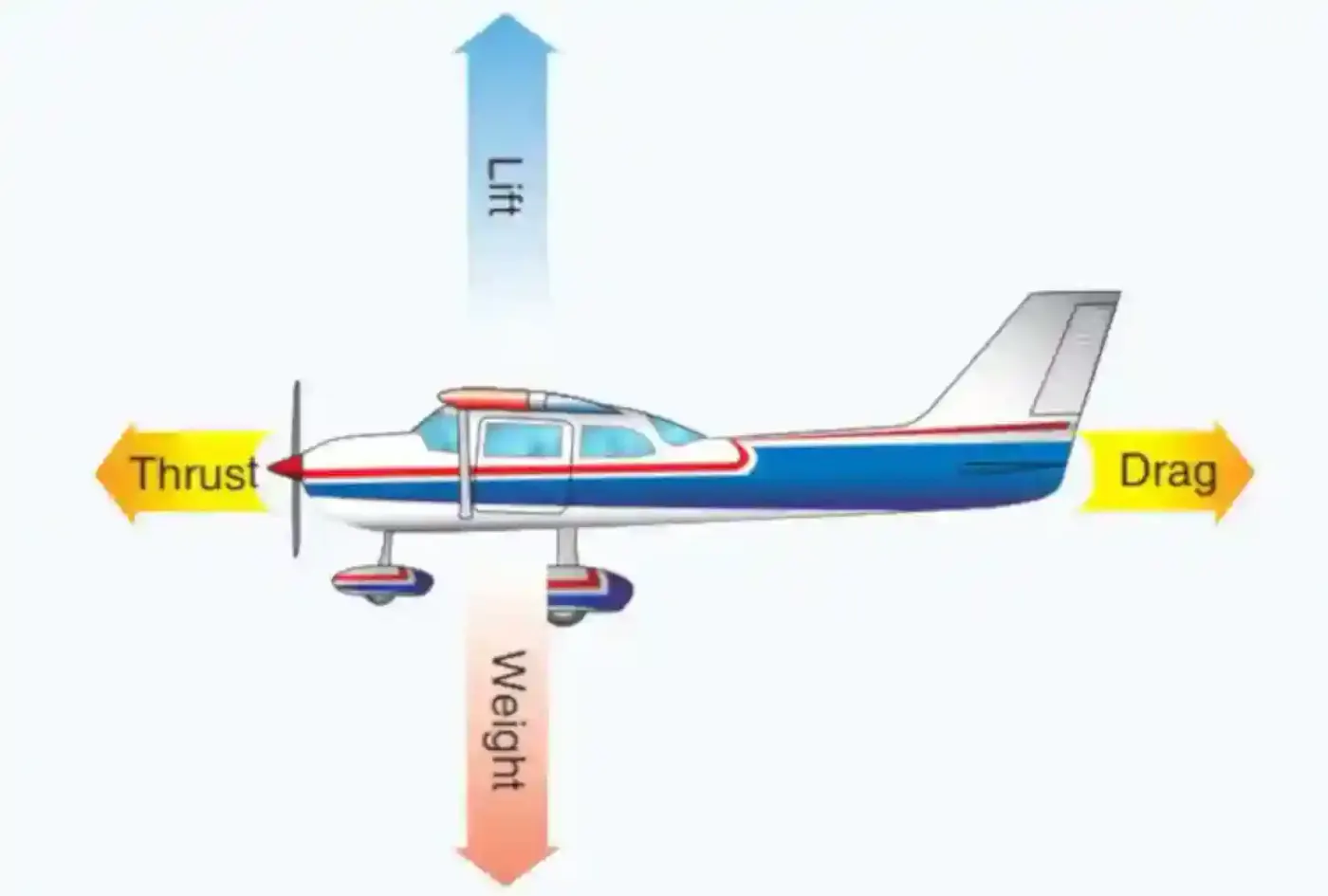
Common examples of aircraft include airplanes, helicopters, airships (including blimps), gliders, paramotors and hot air ballons.
WEIGHTS IN AIRCRAFT :
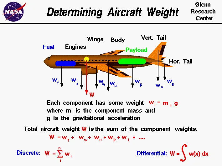
When looking at different aircraft's specifications or in POHs/AFMs, there are several different weights of the aircraft mentioned (e.g. maximum take-off weight, maximum landing weight, operating empty weight).
The weights that are to be taken into consideration in an aircraft are :
Manufacturer's empty weight (MEW) :
Also called Manufacturer's Weight Empty (MWE) or Licensed Empty Weight
It is the weight of the aircraft "as built" and includes the weight of the structure, power plant, furnishings, installations, systems and other equipment that are considered an integral part of an aircraft.
This excludes any baggage, passengers, or usable fuel.
Zero fuel weight (ZFW) :
This is the total weight of the airplane and all its contents (including unusable fuel), but excluding the total weight of the usable fuel on board.
As a flight progresses and fuel is consumed, the total weight of the airplane reduces, but the ZFW remains constant.
Maximum zero fuel weight (MZFW) is the maximum weight allowed before usable fuel and other specified usable agents (engine injection fluid, and other consumable propulsion agents) are loaded.
Operating empty weight(OEW) :
(Roughly equivalent to basic empty weight on light aircraft)
It is the basic weight of an aircraft including the crew, all fluids necessary for operation such as engine oil, engine coolant, water, unusable fuel and all operator items and equipment required for flight but excluding usable fuel and the payload.
Payload :
It is the carrying capacity of an aircraft. It includes cargo, people, extra fuel. In the case of a commercial airliner, it may refer only to revenue-generating cargo or paying passengers.
Maximum take off weight(MTOW) :
This is the maximum weight at which the pilot of the aircraft is allowed to attempt to take off.
Regulated take off weight (RTOW) :
Depending on different factors (e.g. flap setting, altitude, air temperature, length of runway), RTOW or maximum permissible takeoff weight varies for each takeoff. It can never be higher than MTOW.
Maximum landing weights (MLW) :
This maximum weight at which an aircraft is permitted to land.
Maximum ramp weight (MRW) :
This term is also called maximum taxi weight (MTW)
It is the maximum weight authorized for maneuvering (taxiing or towing) an aircraft on the ground.
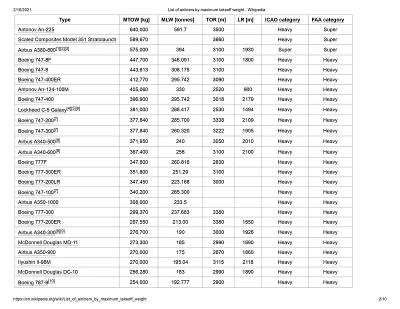
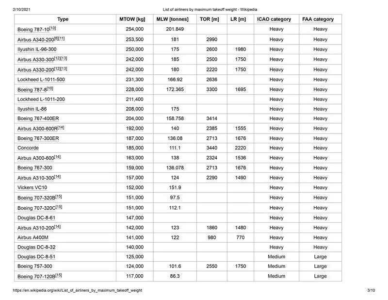
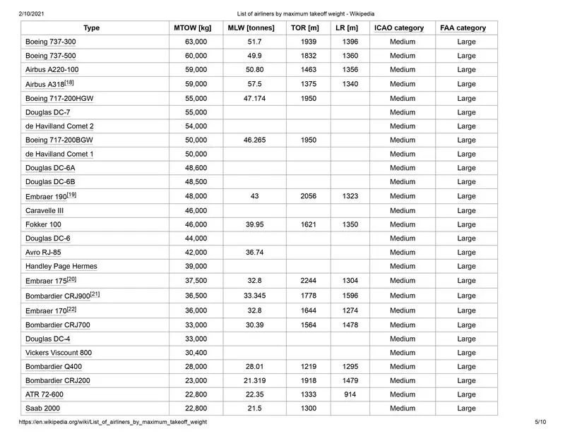
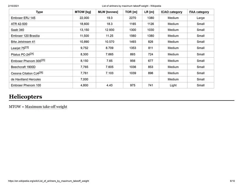
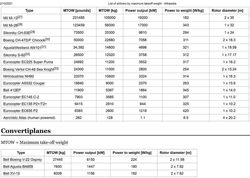
TYPES OF AIRCRAFTS AND ITS WEIGHTS :

MTOW = Maximum take-off weight, MLW = Maximum landing weight, TOR = Take-off run.
 v
v 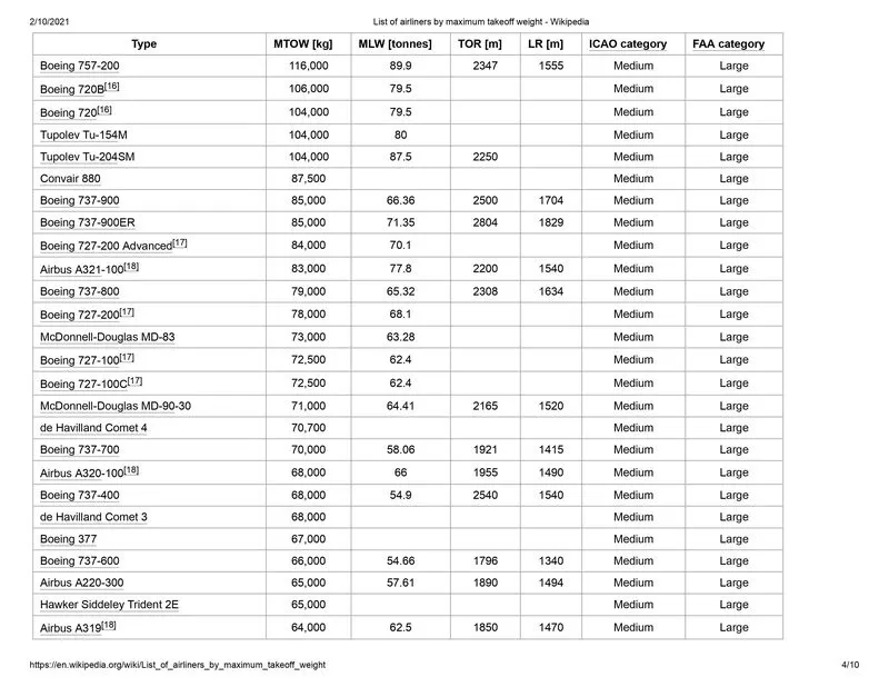
QUESTION 2:
Is there any difference between ground speed and air speed?
EXPLAINATION :
GROUND SPEED :
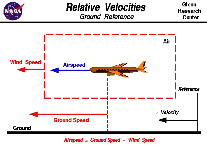
It is the speed of the aircraft relative to the (immobile) ground.
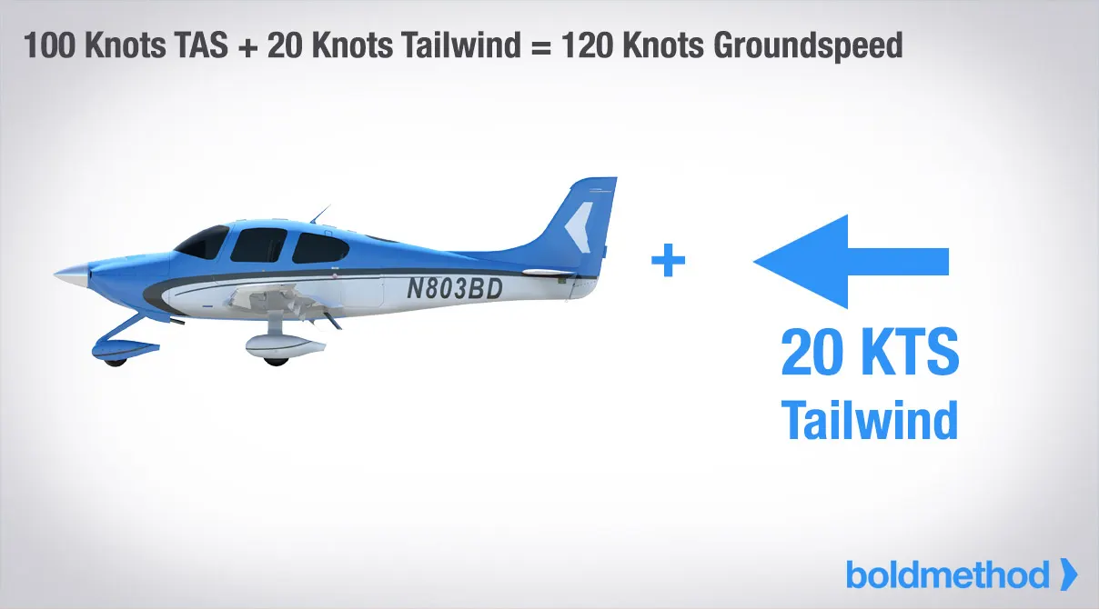
The movement of your airplane relative to the ground is called groundspeed. It's true airspeed corrected for wind. With a true airspeed of 100 knots and a tailwind of 20 knots, you'd be flying a groundspeed of 120 knots.
If you shot a police radar gun at a plane flying by, you'd be measuring groundspeed of the airplane, assuming the officer was stationary.
AIR SPEED :
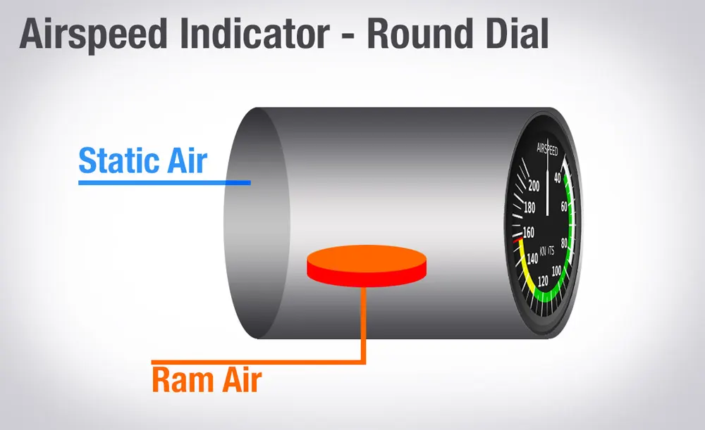
It is obtained by measuring the difference in airpressure around the aircraft and the airpressure caused by propulsion.
There are also 3 types of air speed :
1.Indicated air speed (IAS) :
This one's pretty simple. It's read right off your air speed indicator and is usually what you'll reference in the cockpit for speed changes. The speed limits of the sky, like not exceeding 250 knots below 10,000 feet MSL, are all written as indicated airspeed values.
2. TRUE AIR SPEED :
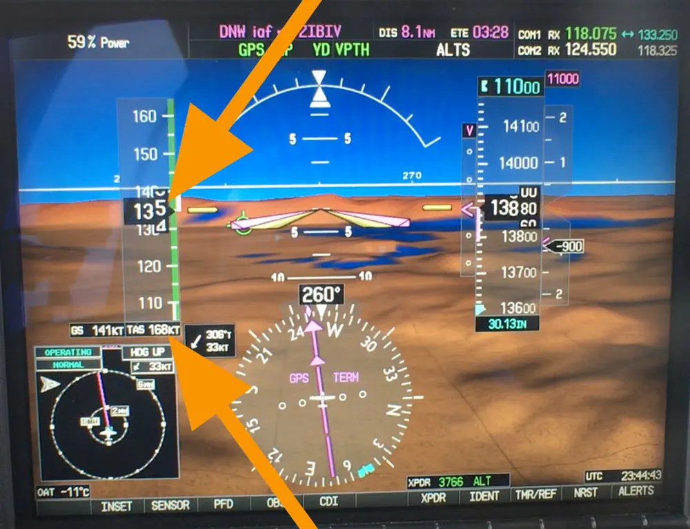
True airspeed is the speed of your aircraft relative to the air it's flying through. As you climb, true airspeed is higher than your indicated airspeed. Pressure decreases with higher altitudes, so for any given true airspeed, as you climb, fewer and fewer air molecules will enter the pitot tube. Because of that, indicated airspeed will be less than true airspeed. In fact, for every thousand feet above sea level, true airspeed is about 2% higher than indicated airspeed. So at 10,000 feet, true airspeed is roughly 20% faster than what you read off your airspeed indicator.
Many aircraft, such as those with gas turbine engines, can reach a higher TAS at higher altitudes because their engines are more efficient at higher altitudes.
3. CALIBRATED AIR SPEED :
Calibrated airspeed is indicated airspeed corrected for instrument and positional errors. At certain airspeeds and with certain flap settings, the installation and instrument errors may total several knots. This error is generally greatest at low airspeeds, with nose high pitch attitudes.
When flying at sea level under International Standard Atmosphere (ISA) conditions (15 degrees Celsius, 29.92 inches of mercury, 0% humidity), calibrated airspeed is the same as true airspeed. If there is no wind it is also the same as ground speed.
QUESTION 3:
Why is it not recommended to use aircraft engine power to move it on the ground at Airport?
EXPLAINATION :
- We are assuming passenger commuter aircraft and large airliners. Aircraft move using their own engine power all the time on the airport apron and taxiways under their own power to go towards runways and after landing taxi to their assigned gate.
- The only time they use external assistance is to pushback from the gate. Large turbofan aircraft need help to reverse via a pushback tractor. The engines are turned on after the pushback is complete and the aircraft can move forward under It’s own power.
- To be accurate, some aircraft can reverse using a variable pitch prop or thrust reversing on turbofans but generally reversing is done via pushback tractors. Blasting jet reversers blows debris In the crowded gate area creating foreign object damage hazard for adjacent aircraft, gate equipment or terminal waiting area glass windows.
- Whether jets or prop airplanes, we use the aircraft’s (engine) power to move on the airfield.
- All large aircraft are pushed back, they could use there power to do it but due to the noise and fumes plus they burn a lot of fuel. Sometimes they are towed into a spot due to it being a small parking space for safety.
QUESTION 4:
How an aircraft is pushed to runway when its ready to take off?
EXPLAINATION :
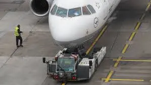
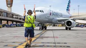
Taxiing refers to the movement of an aircraft on the ground, under its own power. The aircraft moves on wheels. An airplane uses taxiways to taxi from one place on an airport to another; for example, when moving from a terminal to the runway.
The aircrafts always moves on the ground following the yellow lines, to avoid any collision with the surrounding buildings, vehicles or other aircrafts. The taxiing motion has a speed limit. Before making a turn, the pilot reduces the speed further to prevent tire skids. Just like cars, there is a certain list of priorities during taxiing. The aircrafts that are landing or taking off have higher priority. The other aircrafts have to wait for these aircrafts before they start or continue taxiing.
The thrust to propel the aircraft forward comes from its propellers or jet engines. Steering is achieved by turning a nose wheel or tail wheel/rudder; the pilot controlling the direction travelled with their feet. The use of engine thrust near terminals is restricted due to the possibility of jet blast damage. This is why the aircrafts are pushed back from the buildings by a vehicle before they can start their own engines for taxiing
TAKE OFF :
Takeoff is the phase of flight in which an aircraft goes through a transition from moving along the ground (taxiing) to flying in the air, usually starting on a runway. Usually the engines are run at full power during takeoff. Following the taxi motion, the aircraft stops at the starting line of the runway. Before takeoff, the engines, particularly piston engines, are routinely run up at high power to check for engine-related problems. This makes a consid- erable noise. When the pilot releases the brakes, the aircraft starts accelerating rapidly until the necessary speed for take-off is achieved.

The takeoff speed required varies with air den- sity, aircraft weight, and aircraft configuration (flap and/or slat position, as applicable). Air density is affected by factors such as field ele- vation and air temperature.
Operations with transport category aircraft employ the concept of the takeoff V-Speeds, V1 and V2. These speeds are determined not only by the above factors affecting takeoff perform- ance, but also by the length and slope of the runway. Below V1, in case of critical failures, the takeoff should be aborted; above V1 the pilot continues the takeoff and returns for land- ing. After the co-pilot calls V1, Then, V2 (the safe takeoff speed) is called. This speed must be maintained after an engine failure to meet per- formance targets for rate of climb and angle of climb.
The speeds needed for takeoff are relative to the motion of the air (indicated airspeed). A head wind will reduce the ground speed needed for takeoff, as there is a greater flow of air over the wings. This is why the aircrafts always take off against the wind. Side wind is not preferred as it would disturb the stability of the aircraft. Typical takeoff air speeds for jetliners are in the 130–155 knot range (150–180 mph, 240–285 km/h). For a given aircraft, the takeoff speed is usually directly proportional to the aircraft weight; the heavier the weight, the greater the speed needed. Some aircraft have difficulty generating enough lift at the low speeds encountered during takeoff. These are therefore fitted with high-lift devices, often including slats and usually flaps, which increase the camber of the wing, making it more effective at low speed, thus creating more lift. These have to be deployed from the wing before performing any maneuver.
At the beginning of the climb phase, the wheels are retracted into the aircraft and the undercarriage doors are closed. This operation is audible by the passengers as a noise coming from below the floor.
QUESTION 5 :
Learn about take off power, tyre design, rolling resistance, tyre pressure, brake forces when landing?
EXPLAINATION :
Take of power required to keep the aircraft in the air without fail:
-
The take off power required mainly depends upon the kinetic energy of the vehicle and the height i.e, potential energy of the aircraft.
- The total energy of an aircraft flying in the atmosphere can be calculated from the below energy equation:
E = ½ m v2 + mgh
here m = total mass of the aircraft
v = velocity with which air craft is moving.
g = acceleration due to gravity
h = height at which aircraft is moving
- A Boeing 737-300 has a maximum takeoff weight of 5.65 × 10⁴ kg, a cruise altitude of h = 10,195 m, and cruise speed of 221 m/sec. Inserting these numbers into the above equation, we obtain 7.03 GJ for the energy at cruise conditions. [3] However, the engines mounted onto the wings of the plane are required to provide additional energy per time, power, in order to keep the aircraft flying at a constant altitude and speed.
- The extra power needed to overcome the drag acting on the airplane can be given by the following equation :
P = (dh/dt) m g
Here dh/dt = the decent speed required to keep the plane's speed constant if the engines fail.
m = mass of the aircraft
g = acceleration due to gravity
Tyre Design :
Aircraft tires can easily be taken for granted. Their simplistic appearance may lead some to a false feeling of complacency. Many technicians are not aware of the critical design factors that go into every aircraft tire in use today. Seemingly minor flaws can lead to disastrous results, and inadequate maintenance practices can cause shortened tire life and even cause unsafe operating conditions.
When one considers the forces that aircraft tires endure, it seems amazing that engineers were ever able to develop these special products. Some tires are subjected to speeds as fast as a race car while at the same time supporting more weight than the largest land moving machines. They go through cyclic exposure to varying temperatures and pressures. These factors make aircraft tire design a critical process and tire maintenance an ever important step in safe aircraft operation.
Designing aircraft tires is a very intense undertaking. Once an aircraft manufacturer goes to the tire manufacturer with the size and weight requirements, the tire manufacturer begins the process of designing a tire that meets the needs of the aircraft manufacturer as well as all regulatory requirements — including foreign regulations in many cases.
Engineers are challenged with designing tires with cool running, heat-resistant materials while simultaneously exceeding tire service requirements. Tire prototypes are put through rigorous tests that simulate cycles of landings, take-offs, and taxi operations. It is only after the tires pass all mandatory tests and meet the requirements of the aircraft manufacturer and airworthiness authorities that the tires are put into production.
Two types of tires are used in aircraft applications — bias-ply tires and radial tires. Although both types of tires share some similarities in design, there are differences that need to be noted.
Bias-ply tire construction :
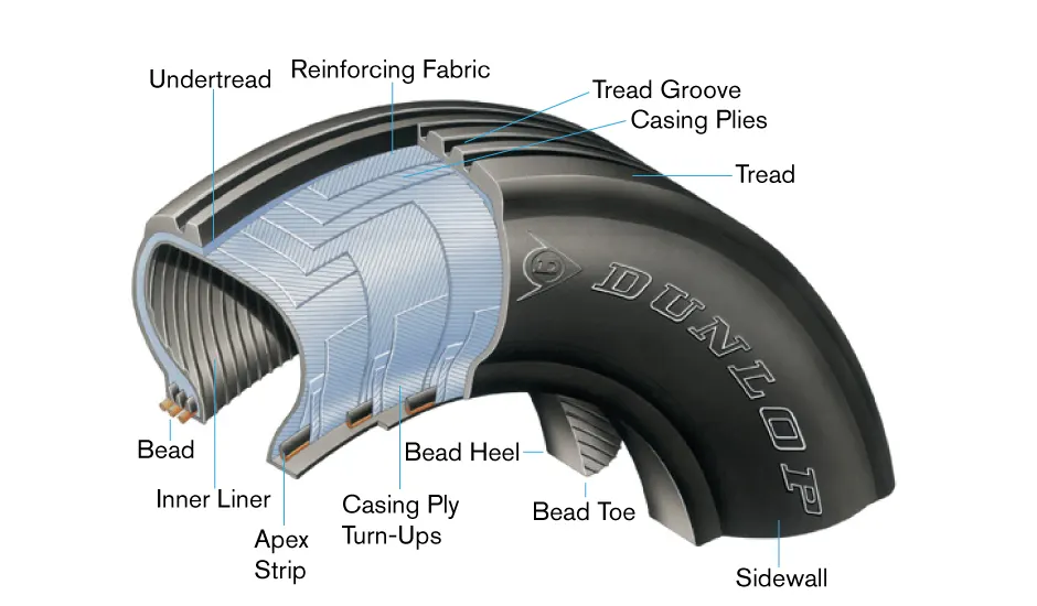
A cutaway of a typical bias-ply tire is shown in Figure 1. Bias-ply tires are popular choices for aircraft tires because of their durability and retreadability. The tire construction consists of the following components:
Tread: The tread is made of rubber mixed with other additives to obtain the desired level of toughness, durability, and resistance to wear. The tread pattern is designed to aircraft operational requirements, with the ribbed tread design used widely due to its good traction under varying runway conditions.
Sidewall: The sidewall is a protective layer of rubber that covers the outer casing ply. It extends from the tread edge to the bead area.
Tread Reinforcing Ply: One or more layers of fabric that strengthens and stabilizes the tread area for high-speed operation. It also serves as a reference for the buffing process when tires are retreaded.
Buff Line Cushion: The buff line cushion is made of rubber compound to enhance the adhesion between the tread reinforcing ply and the breakers or casing plies. It is of sufficient thickness to allow for the removal of the old tread when the tire is retreaded.
Breakers: Breakers are reinforcing plies of rubber-coated fabric placed under the buff line cushion to protect casing plies and strengthen and stabilize the tread area. They are considered an integral part of the casing construction.
Casing Plies: Alternate layers of rubber-coated fabric (running at opposite angles to one another) provide the strength of the tire.
Wire Beads: Hoops of high tensile strength steel wire that anchor the casing plies and provide a firm mounting surface on the wheel. The outer edge of the bead that fits against the wheel flange is called the bead heel. The inner bead edge is called the bead toe.
Apex Strip: A wedge of rubber affixed to the top of the bead bundle.
Flippers: Layers of rubberized fabric that help anchor the bead wires to the casing and improve the durability of the tire.
Ply Turnups: The casing plies are anchored by wrapping them around the wire beads, thus forming the ply turnups.
Chafer: A protective layer of rubber and/or fabric located between the casing plies and wheel to minimize chafing.
Liner: In tubeless tires, the liner is a layer of low permeability rubber that acts as a built-in tube and restricts gas from diffusing into the casing plies. In tube-type tires, a thinner liner is used to prevent tube chafing against the inside ply.
Radial-ply tire construction :
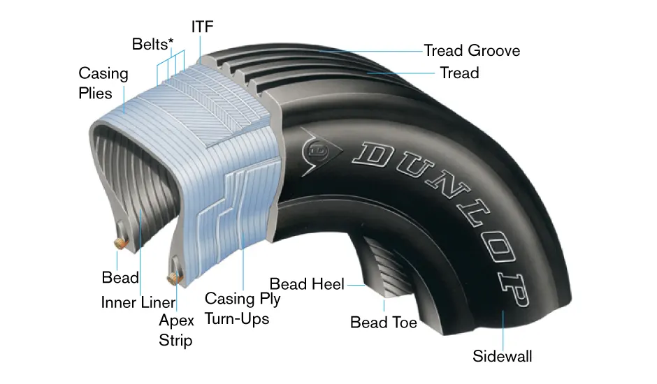
With their rigid belt, they provide increased landings and reduced rolling resistance. They have fewer components in their construction and are lighter than similarly sized bias ply tires. Components that differ from bias-ply construction as follows:
Overlay: A layer of reinforcing rubber coated fabric placed on top of the belts to aid in high speed operation.
Belt Plies: A composite structure that stiffens the tread area for increased landings. The belt plies increase the tire strength in the tread area.
Casing Plies: As in bias-ply tires, the casing plies are layers of rubber-coated fabric. However, unlike those in bias plies that run at opposite angles to one another, radial plies run radially from bead to bead.
Chippers: The chippers are layers of rubber-coated fabric applied at diagonal angles that improve the durability of the tire in the bead area.
Tire inspection :
In order to ensure safety and increase tire life, systematic inspections of mounted tires should be performed. A word of warning — Never probe cracks, cuts, or embedded foreign objects while the tire is inflated! Serious injuries could result. In addition, defects such as cuts, cracks, and bulges should be marked with a crayon or chalk prior to deflation since the defects may disappear when the tire is deflated. The following should be checked:
Tread wear: Treads should be visually inspected for wear. The tire should be replaced when tread has worn to the base of any groove at any spot or to a minimum depth specified in the aircraft maintenance manual. Tread wear can also be an indication of improper tire inflation. Refer to Figure 3 for tread wear indications.
Tread cuts: The tire should be inspected for cuts and other foreign damage. Follow the criteria from the applicable aircraft maintenance manual. If no specific criteria is outlined in the manual, the following can be used for guidance in determining tread cuts.
A-Normal
Even tread wear on this tire indicates that it has been properly maintained and run at correct inflation pressure.
B-Excessive
Worn to the breaker/casing plies, the tire should not be left in service or retreaded.
C-Overinflation
Continuous overinflation accelerates center tread wear. It reduces traction while making tread more susceptible to cutting.
D-Underinflation
Excessive tread shoulder wear results from chronic underinflation. It increases the chance of damaging shoulders and sidewalls which shortens tire life because of excessive flex heating.
• Any cut that extends into the casing plies on bias tires.
• Any cut into the belt on radial tires.
• Any cut that extends across one or more rubber tread ribs to the fabric.
• Rib undercutting at the base of any
cut or tread splice warrants replacement.
Sidewall damage: Tires should be replaced if weatherchecking, cracking, cuts, or snags extend down to the casing ply in the sidewall and bead areas.
Bulges: Bulges in any part of the tire tread, sidewall, or bead area are indicative of a separation or damaged tire. The area should be marked and the tire should be removed from service immediately.
Fabric fraying/groove cracking: Tires should be removed from service if groove cracking exposes any fabric or if cracking undercuts the tread ribs.
Flat spots: Flat spots can be caused by braking during touchdown or hydroplaning skids. Tires with flat spots don’t necessarily need to be removed from service unless fabric is exposed. However, if there is an objectionable unbalance issue, the tire assembly can be re-balanced or removed from service.
Radial tire sidewall indentation: Remove tire from service with 3mm or greater sidewall indentation.
Beads: The tire bead areas should be inspected next to the wheel flanges for heat-induced damage, especially if brake drag or severe braking was experienced.
Tire clearance: The tires should be inspected for marks that might indicate rubbing the wheel area due to inadequate clearance.
Wheel assemblies: The wheel assemblies should be inspected for damage. Wheels that are cracked or damaged should be taken out of service for repair or replacement.
Tire inflation
Tire inflation is the most critical issue when inspecting installed tires. Although overinflation can damage the tires by causing uneven tread wear, reduced traction, increased susceptibility to cutting, and increased stress on the wheel assemblies, underinflation is by far more damaging. Underinflation produces uneven tread wear and shortens tire life due to excessive flex heating. The bead area of an underinflated tire can be 50 percent hotter than that of a properly inflated one. Heat is damaging to tire rubber compounds and fabrics. It contributes to tread and carcass separations and bead failures.
Ideally, tire pressure should be checked with a calibrated gauge prior to each flight. At a minimum, they should be checked daily. Do not make the mistake of relying on your "calibrated eye" to determine tire inflation. Tire inflation is difficult to determine visually, especially in tandem configurations. Always use a gauge to check inflation. If servicing is required, dry nitrogen should be used due to its inability to sustain combustion. Also, degradation of the casing plies and liner due to oxidation occurs if regular shop air is used. Nitrogen also helps to deter corrosion on the wheel assembly.
It is a good practice to establish a method of recording tire servicing actions. This aids in identifying chronic leakage problems.
Temperature changes
Another thing to remember pertaining to tire inflation is the change in pressure with temperature changes. For every five degrees Fahrenheit change in temperature, there is approximately a one-percent pressure change in the same direction. This should be taken into consideration if the aircraft is going to be subjected to extreme ground temperature changes. In that case, the tires should be inflated to ensure the minimum required pressure is maintained for the cooler climate. Remember to always check tire pressures when they are at ambient temperature. Checking pressures on hot tires could mask an underinflation condition.
One thing that needs to be noted on newly installed tires is that the tire pressure will drop initially due to tire expansion. The tire pressure should be checked closely until it stabilizes — usually after about 12 hours at rated inflation. If it still exhibits a significant pressure drop after that, the tire should be inspected for possible leaks and corrective action taken.
Protecting tires
Tires should be kept clean and free from oil, hydraulic fluids, grease, tar, and solvents. All of these chemicals have a deteriorating effect on the rubber in the tires. Any contaminant should be wiped off with denatured alcohol followed by a soap and water wash.
Aircraft tires are affected by sunlight and weather extremes. Installation of protective covers can help protect tires on aircraft that are tied down outside.
Operational considerations
Whenever taxiing or towing aircraft, the aircraft manufacturer’s recommended operational procedures should always be followed. It is always prudent to use large radius turns and low speeds to prevent shoulder damage, tread scrubbing, and overheating. Care should also be taken to avoid running over hazardous areas. Tire damage can result from potholes, cracks in the pavement, or stepoffs from pavement to ground.
The areas where the aircraft will be operated should be kept free from debris. In addition to the damage potential FOD (Foreign Object Debris) poses to engines, it can cause considerable damage to tires if it becomes embedded in the tire tread.
This article has briefly discussed some basics on tire composition as well as some inspection and preventive maintenance techniques. Always refer to the applicable aircraft maintenance manual when working with aircraft tires. In addition, the FAA requires tire manufacturers to provide a care and maintenance manual for their products. This is an additional resource that is available to assist in tire maintenance and inspection procedures. With proper attention during inspection and good preventive maintenance practices, your aircraft tires should provide trouble-free service for many landings.
Tube-Type or Tubeless
ROLLING RESISTANCE IN AIRCRAFT :
 .
.
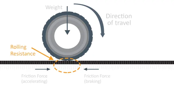
Rolling resistance, sometimes called rolling friction or rolling drag, is the force resisting the motion when a body (such as a ball, tire, or wheel) rolls on a surface. It is mainly caused by non-elastic effects; that is, not all the energy needed for deformation (or movement) of the wheel, roadbed, etc., is recovered when the pressure is removed. Two forms of this are hysterises losses and permanent (plastic) deformation of the object or the surface (e.g. soil). Another cause of rolling resistance lies in the slippage between the wheel and the surface, which dissipates energy.
The rolling resistance force will be given by the equation as :
F = μ*mg
here :
μ = rolling resistance coefficient
m = total mass of aircraft
g = acceleration due to gravity
But when we consider the extreme condition the surace when considered with a snow we take many considerations into account :
When taking off from a runway covered with slush, standing water or snow, the required take-off ground-run distance will be longer than on a dry runway. This is the result of the fact thatslush, standing water and snow on the runway will generate a rolling resistance that increasesthe total resistance on the aircraft during the ground-run.
Snow is a porous, permeable aggregate of ice grains, which can be single crystals, or closegroupings of several crystals. Air and water vapor surround the crystals. Snow is a complicatedmaterial because of the variety of forms it can take and because it is thermodynamicallyunstable, which means that the physical properties of the snow can change with time (known assnow metamorphism). A large number of different types of snow are known. A possibleclassification of these types including typical densities, is given as follows:
•New snow (50-200 kg/m3)
•Powder snow (200-450 kg/m3)
•Compacted snow (450-700 kg/m3)
•Wet snow (300-700 kg/m3)
All these types of snow are compressible. This means that the volume changes when the snow isloaded. This volume change becomes evident as surface compaction. Density is probably themost useful single parameter of snow properties because e.g. structural characteristics showsome correlation with density. The compression strength of snow, and thus its bearing capacity,also appears to be strongly influenced by its density. Below a density of 400 kg/m3 the bearingcapacity of snow is usually very low resulting in large volume changes of the snow when it isloaded. At higher densities higher loads are required to compress the snow. Whenever snow issubjected to loads e.g. by moving the snow with a bulldozer or running a tire over it, the snowbecomes stronger than natural snow of the same density. This is a result of bond growthbetween the ice crystals. As already pointed out, snow is metamorphic. Environmentalinfluences like wind, temperature fluctuations, and rain can change the characteristics of snowwithin days and even within hours.
The total rolling resistance of an aircraft rolling along a snow-covered runway is given by:
Drolling = Dr+Dc+Dd
In which Dr is the rolling resistance on a dry hard surface. The equations presented in this paperfor Dc and Dd are for single tires. A complete aircraft has at least 3 tires, one on each mainlanding gear and one on the nose landing gear. To obtain the total aircraft rolling resistance dueto snow, the resistance Dc and Dd for each single tire have to be calculated and summed.
TYRE PRESSURE :
An aircraft tire or tyre is designed to withstand extremely heavy loads for short durations. The number of tires required for aircraft increases with the weight of the aircraft, as the weight of the airplane needs to be distributed more evenly. Aircraft tire tread patterns are designed to facilitate stability in high crosswood conditions, to channel water away to prevent hydroplaning, and for braking effect.
Aircraft tires also include fusible plugs (which are assembled on the inside of the wheels), designed to melt at a certain temperature. Tires often overheat if maximum braking is applied during an aborted takeoff or an emergency landing. The fuses provide a safer failure mode that prevents tire explosions by deflating in a controlled manner, thus minimizing damage to aircraft and objects in the surrounding environment.
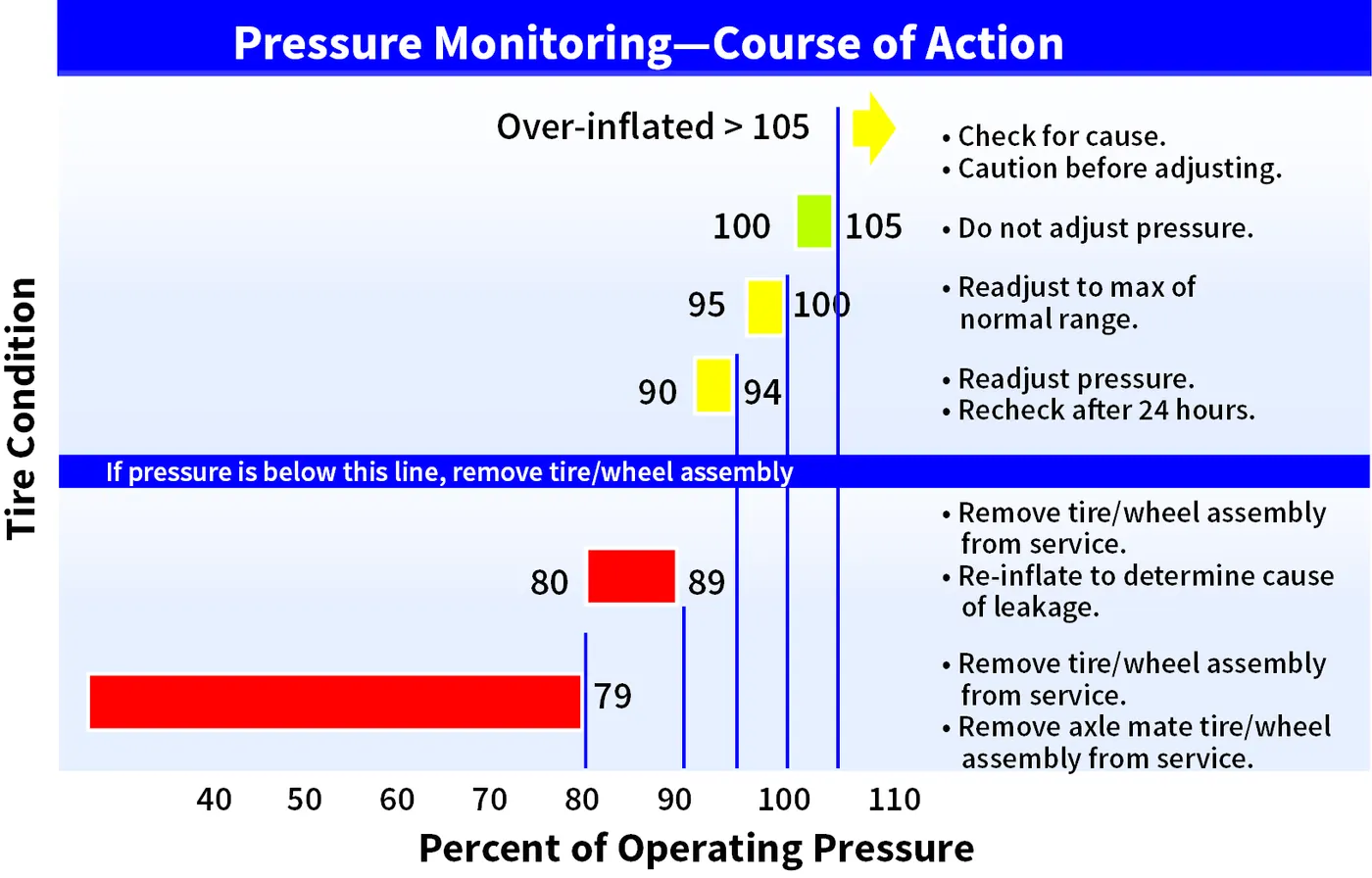
The below image shows the comparision between the car and aircraft tyre pressure comparision :
| CAR TYRE | AIRCRAFT (1) | AIR CRAFT (2) | |
| Typical | (737 NLG) | (737 NLG) | (F-16 Blk 40 MLG) |
| Size | P205/75 R15 | 27x7.75 R15 | 27.75x8.75R14.5 |
| Outside Diameter | 27.2 inch | 27 inch | 27.75 inch |
| Selection Width | 8.1 inch | 7.75 inch | 8.75 inch |
| Max Inflation | 35 psi | 200 psi | 320psi |
| Max Load | 1,598 lbs | 9,650 lbs | 21,500 lbs. |
| Speed Rating | 106 mph | 225 mph | 259 mph |
| Operation | Continuous | Intermittent | Intermittent |
| Temperature | Equilibrium | No Equilibrium | No Equilibrium |
By the above variation we can assume that what will be the pressure of aircrafts with respect to the normal 4 wheeler vehicles.
BRAKES FORCES WHILE LANDING :
Early aircraft had a single braking system with no backup or redundancy. This was seen as impractical by the operators and unacceptable by the regulating authorities so manufacturers were soon incorporating more robust braking systems into their designs. Some of the earlier solutions simply addressed the loss of the primary hydraulic pump and incorporated hand pumps or electrically driven hydraulic pumps to provide an alternate source of hydraulic pressure. These solutions did not address failures due to loss of fluid and were deemed inadequate. To overcome this, some manufacturers such as Convair incorporated a compressed air system into their designs for emergency braking. While it achieved the requirement of providing an independent means of activating the brakes, it was limited in that it did not allow for differential braking and in that the tank contained a finite amount of compressed air. Braking redundancy in most large passenger aircraft today is achieved by multiple, independent hydraulic systems backed up by accumulators. These systems allow for several layers of failure without resulting in total loss of braking capability.
Brake System Enhancements
Anti-skid, auto-brake, brake temperature indicators and brake fans are all systems which enhance the performance of the aircraft brakes.
Anti-skid System
The anti-skid system, through various mechanisms, compares the speed of the aircraft with the rotational speed of each main wheel. If the speed of any wheel is too slow for the existing aircraft speed, the brake on that wheel (or wheels) is released momentarily to allow the wheel speed to increase and prevent the wheel from skidding. The system is fully automatic and is active from immediately after initial wheel spin up on landing (during which time brake activation might (or might not) be inhibited) down to a design limited minimum speed; usually about 15 knots. Anti-skid systems are designed to minimise aquaplanning and the potential tyre damage which can occur when a wheel is locked or rotating at a speed which does not correspond to the speed of the aircraft. Anti-skid removes the possibility of reverted rubber skids caused by locked wheels. An anti-skid system also greatly improves stopping distance on substandard surfaces such as gravel or grass and is particularly effective on surfaces contaminated with frozen contaminants such as ice or slush by ensuring maximum effective breaking.
Auto-brake Systems
Auto-brake systems can be used on takeoff where they will provide maximum braking in the event of a rejected take-off and on landing where they will provide a scheduled rate of deceleration (dependent upon the auto-brake level selected) using only a single brake application. These features combine to optimize the brake usage with respect to the requirement and to minimize brake wear.
QUESTION 6 :
With necessary assumptions, calculate the force and power required to push / pull an aircraft by a towing vehicle?
Let us assume that an air craft i.e, light weight jet engines can be moved with this tow vehicles
Assuming the Tow vehicle as LEKTRO series model : AP8950SDB-AL-250
AIR LINE TOW VEHICLES BY LEKTRO
The specifications of this towing vehicle is mentioned in the above link and the same values were taken as a reference.
To calculate the force and Power to push or pull an aircraft by a towing vehicle we need to ṭake rolling resistance and aerodynamics of the vehicle into consideration
ROLLING RESISTANCE FORCE :
Frr = μ*m*g
μ = 0.01 (for asphalt road conditions for heavy trucks)
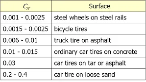
mass of towing vehicle let be = 50000 kg
mass of boeing 757 = 127006 kg
m = total mass of aircraft and towing vehicle = 170006 kg
radius of towing vehicle = 33 cm = 0.33 m
g = 9.81 m/s^2
Frr = 0.01*(170006)*9.81
Frr = 16677.58 N
Frr = 16.677 KN
AERODYNAMIC FORCE :
Fa = 0.5*RHO*A*V^2*Cd
let us assume :
here A = frontal area = width*height = 15*30 = 450 m^2
RHO = density of air = According to the International Standard Atmosphere (ISA) values—15° C at sea level—the density of dry air is at 1.225 kg/m^3
V = velocity with which vehicle is travelling(loaded) = 6.4 KMPH = 6.4*5/18 = 1.783 m/s
Cd = drag coefficient of aircraft = 0.02
Velocity of towing = 6.4 KMPH = 1.783 m/s
Fa = 0.5*1.225*450*(1.783)^2*0.02
Aerodynamic force = 17.52 N
Total force(F) = Frr+Fa = 16677.58+17.52 = 16695.1 N or 16.695 KN
POWER REQUIRED TO MOVE THE VEHICLE :
Power required is = F*V
= 16.695*1.611
= 26.89 KW
Torque required = F*radius = F*R
= 16.695*0.33
= 5509.35 Nm
Therefore power and torque of vehicle obtained with a speed 6 KMPH is
P = 26.89 KW
T = 5509.35 Nm
QUESTION 7 :
Design an electric powertrain with type of motor, it’s power rating, and energy requirement to fulfill aircraft towing application. Estimate the duty cycle range to control the aircraft speed from zero to highest. Make all require assumptions. Prepare a table of assumed parameters. Draw a block diagram of powertrain?
EXPLAINATION :
So from the initial all the values taken into consideration of towing vehicle and air craft :
mass of towing vehicle let be = 50000 kg
mass of boeing 757 = 127006 kg
radius of towing vehicle = 33 cm = 0.33 m
Acceleration due to gravity(g) = 9.81 m/s^2
rolling resistance coefficient(μ) = 0.01 (for asphalt road conditions for heavy trucks)
Frontal area of the aircraft(A) = 450 m^2
density of air(According to the International Standard Atmosphere (ISA) values—15° C at sea level—the density of dry air) = 1.225 kg/m^3
velocity with which vehicle is travelling(loaded) = 1.611 m/s or 6 KMPH
Cd = drag coefficient of aircraft = 0.02
Rolling resistance force for aircraft to be towed(Frr) = 16.677 KN
Aerodynamic force = 17.52 N
Power required to move the aircraft by tow vehicle = 26.89 KW
Torque required to move the aircraft by towing vehicle = 5509.35 Nm
BLOCK DIAGRAM OF ELECTRIC VEHICLE :
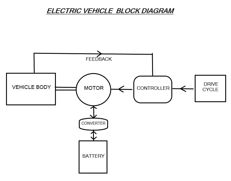
So from the above results of power required is 26.89 KW and now the particular rated powered motor will be required to assist the towing vehicle to move the aircraft.
Here we are using the BLDC Motor as it gives a good constant torque, work efficiently and also gets cooled by conduction and requires no additional cooling mechanism.
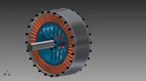
Motor Design :
- So let us assume a 45 KW DC Brushless motor :
- Nominal Power: 45KW
- Nominal Voltage: 230v
- Nominal current:200A
- Winding configuration : Delta
- RPM: 2600
- Construction : 48 slot, 40 Magnets Neodymium
- Lamination Grade M330
- Cooling : Glycol
- Weight: 17Kg
- Copper weight ~ 2.7kg
Windings:
- Can be : delta or Star ( WYE)
- Delta connection will give you higher power per cooper amount, higher RPM, higher current, lower phase voltage.
- STAR will give you lower RPM, higher torque (1,73 more than dela) , higher the voltage, lower the current.
- Can be: concentrated or fractional slot type.
- If there are concentrated can be: LRK, distributed LRK etc.
From the above motor design :
Rated Voltage = 230 V
Rated current = 200 Amps
Rated power = V*I = 230*200 = 46000W = 46 KW
So from the above choosen motor the output power will be 45 KW and the power required by the towing vehicle is 26.89 KW
Input Power to Towing Vehicle = 26.89 KW
Total Power(Rated) can be supplied = 45 KW
Duty cycle Efficiency = Output Power/Input Power
D = 26.89/45
D = 59.75 = 0.60
The Duty cycle percentage = 60%
Total energy supplied to move the towing vehicle = Power input to Tow * time taken to move the aircraft by Towing vehicle
E = P*time(t)
P = 26.89 KW
t = time taken to move the aircraft by towing vehicle = 15 min = 0.25 hrs
E = 26.89*0.25
E = 6.7225 KWh
Energy required to move aircraft by towing vehicle for 15 min with 6 KMPH velocity = 6.7225 KWh
CONCLUSION :
- Listed out the various types and weights of aircrafts.
- Given the difference between ground speed and air speed.
- Given the reasons why aircraft engine is not propelled to move on the ground before it is taken into runway.
- Explained how aircraft is pushed to runway when its ready to take off.
- Learned about take off power, tyre design, rolling resistance, tyre pressure, brake forces when landing.
- Calculated the force and power required to push / pull an aircraft by a towing vehicle.
- Designed the electric vehicle powertrain with motor rating, duty cycle with which motor is controlled using controller and also energy, power, Torque is calculated to move the aircraft with the Towing Vehicle.
REFERENCES :
https://www.masinaelectrica.com/tag/40kw-brushless-motor/
https://www.lektro.com/products/ap8950sdb-al-250/
https://en.wikipedia.org/wiki/Boeing_757
https://en.wikipedia.org/wiki/Aircraft
https://www.aircraftsystemstech.com/p/aircraft-tires-and-tubes-aircraft-tires.html