Project-1: Powertrain for aircraft in runways
Powertrain for aircraft in runways
Objectives
Part A
1. Search and list out the total weight of various types of aircrafts.
2. Is there any difference between ground speed and air speed?
3. Why is it not recommended to use aircraft engine power to move it on the ground at Airport?
4. How an aircraft is pushed to runway when its ready to take off?
5. Learn about take off power, tyre design, rolling resistance, tyre pressure, brake forces when landing.
Part B
6. A. With necessary assumptions, calculate the force and power required to push / pull an aircraft by a towing vehicle.
B. Develop the model for the calculated force and power using Simulink.
7. A. Design an electric powertrain with type of motor, it’s power rating, and energy requirement to fulfill aircraft towing application in Simulink. Estimate the duty cycle range to control the aircraft speed from zero to highest.Make all required assumptions. Prepare a table of assumed parameters. Draw a block diagram of powertrain.
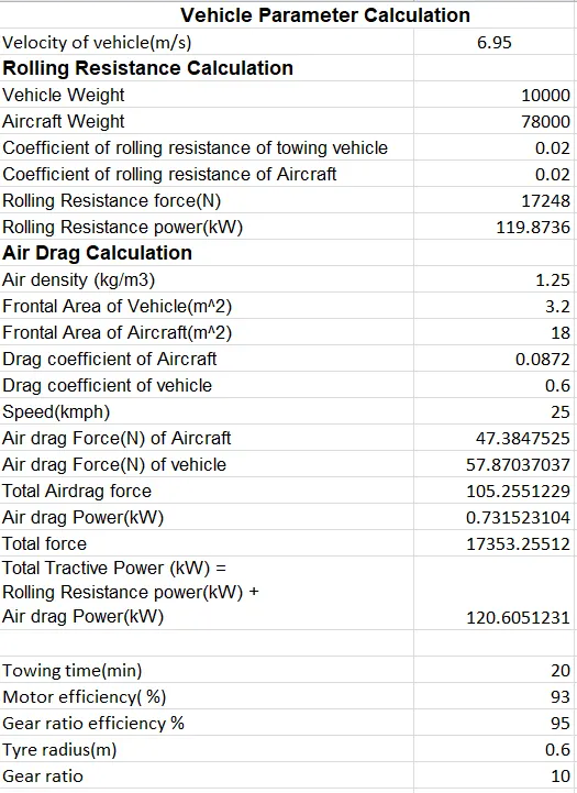
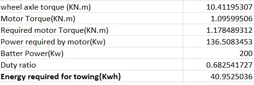
B. Design the parameters in excel sheet.
Q1)Search and list out the total weight of various types of aircrafts.
For each flight, the weights are taken into account for several reasons.
Manufacturer's empty weight (MEW)
Also called Manufacturer's Weight Empty (MWE) or Licensed Empty Weight
It is the weight of the aircraft "as built" and includes the weight of the structure, power plant, furnishings, installations, systems and other equipment that are considered an integral part of an aircraft.
This excludes any baggage, passengers, or usable fuel2.
Zero-fuel weight (ZFW)
This is the total weight of the airplane and all its contents (including unusable fuel), but excluding the total weight of the usable fuel on board.
As a flight progresses and fuel is consumed, the total weight of the airplane reduces, but the ZFW remains constant.
Maximum zero fuel weight (MZFW) is the maximum weight allowed before usable fuel and other specified usable agents (engine injection fluid, and other consumable propulsion agents) are loaded.
Operating empty weight (OEW) (Roughly equivalent to basic empty weight on light aircraft)
It is the basic weight of an aircraft including the crew, all fluids necessary for operation such as engine oil, engine coolant, water, unusable fuel and all operator items and equipment required for flight but excluding usable fuel and the payload.
It is the carrying capacity of an aircraft. It includes cargo, people, extra fuel. In the case of a commercial airliner, it may refer only to revenue-generating cargo or paying passengers.
Maximum takeoff weight (MTOW)
This is the maximum weight at which the pilot of the aircraft is allowed to attempt to take off.
Regulated takeoff weight (RTOW)
Depending on different factors (e.g. flap setting, altitude, air temperature, length of runway), RTOW or maximum permissible takeoff weight varies for each takeoff. It can never be higher than MTOW.
Maximum landing weight (MLW)
This maximum weight at which an aircraft is permitted to land.
The following image depicts takeoff weight components.
Maximum ramp weight (MRW)
also called maximum taxi weight (MTW)
It is the maximum weight authorized for maneuvering (taxiing or towing) an aircraft on the ground.
It is the total aircraft weight at any moment during the flight or ground operation. This decreases during flight due to fuel and oil consumption.
Typical Airplane Weight
Below is a table of some of the most common aircraft flying around our skies today:
| Aircraft | Empty Weight | Max Fuel Weight | Max Cargo Weight | Max Gross Takeoff Weight |
|---|---|---|---|---|
| Antanov AN-225 | 628,000 lbs 285,000 kg |
661,400 lbs 300,000 kg |
417,000 lbs 190,000 kg |
1,411,000 lbs 640,000 kg |
| Airbus A380-800 | 611,000 lbs 277,000 kg |
560,000 lbs 254,000 kg |
185,000 lbs 84,000 kg |
1,268,000 lbs 575,000 kg |
| Boeing 747-800 | 485,300 lbs 220,100 kg |
427,400 lbs 194,000 kg |
295,000 lbs 134,000 kg |
987,000 lbs 447,700 kg |
| Airbus A340-500 | 370,000 lbs 168,000 kg |
386,300 lbs 175,000 kg |
119,000 lbs 54,000 kg |
820,000 lbs 372,000 kg |
| Boeing 777-300ER | 370,000 lbs 168,000 kg | 320,800 lbs 145,500 kg | 148,000 lbs 67,100 kg |
776,000 lbs 352,000 kg |
| Boeing 787-10 | 299,000 lbs 135,500 kg | 223,500 lbs 101,500 kg |
126,300 lbs 57,300 kg | 560,000 lbs 254,000 kg |
| Boeing 737-900 | 98,500 lbs 44,700 kg |
53,100 lbs 24,000 kg |
44,600 lbs 20,200 kg |
187,000 lbs 85,000 kg |
| Airbus A320-100 | 93,900 lbs 42,600 kg |
48,700 lbs 22,100 kg |
44,000 lbs 20,000 kg |
150,000 lbs 68,000 kg |
| Embraer 190 | 63,500 lbs 28,800 kg |
28,600 lbs 13,000 kg |
28,800 lbs 13,100 kg |
106,000 lbs 48,000 kg |
| Gulfstream G650 | 54,000 lbs 24,500 kg | 48,200 lbs 21,900 kg | 6,500 lbs 3,000 kg |
100,000 lbs 45,200 kg |
| Bombardier CRJ900 | 48,160 lbs 21,850 kg | 19,600 lbs 8,900 kg | 6,075 lbs 2,760 kg | 80,500 lbs 36,500 kg |
| Bombardier Q400 | 39,300 lbs 17,800 kg |
11,700 lbs 5,300 kg |
18,700 lbs 8,500 kg |
62,000 lbs 28,000 kg |
|
Learjet 75 |
13,900 lbs 6,300 kg | 6,060 lbs 2,750 kg |
2,900 lbs 1,300 kg |
21,500 lbs 9,700 kg |
| Cessna Citation CJ4 | 10,300 lbs 4,700 kg | 5,800 lbs 2,650 kg |
2,200 lbs 1,000 kg | 17,200 lbs 7,800 kg |
| Beechcraft King Air B100 | 7,100 lbs 3,200 kg | 3,200 lbs 1,450 kg |
4,150 lbs 1,900 kg |
12,000 lbs 5,400 kg |
| Diamond DA50 RG | 3,200 lbs 1,450 kg |
340 lbs 155 lbs |
1,250 lbs 560 kg |
4,400 lbs 2,000 kg |
| Beechcraft Bonaza G36 | 2,500 lbs 1,150 kg | 450 lbs 200 kg |
850 lbs 385 kg |
3,660 lbs 1,660 kg |
| Cessna 206H | 2,200 lbs 990 kg |
520 lbs 235 kg |
1,150 lbs 520 kg |
3,600 lbs 1,630 kg |
| Sirrus SR22 | 2,250 lbs 1,000 kg | 485 lbs 220 kg |
950 lbs 430 kg |
3,600 lbs 1,630 kg |
| Cessna 172R | 1,700 lbs 770 kg |
380 lbs 170 kg |
560 lbs 255 kg |
2,425 lbs 1,100 kg |
Helicopter
MTOW = Maximum take-off weight
| Type | MTOW [pounds] | MTOW [kg] | Power output [kW] |
|---|---|---|---|
| Mil Mi-12 | 231,485 | 105,000 | 19,200 |
| Mil Mi-26 | 123,459 | 56,000 | 17,000 |
| Sikorsky CH-53K | 88,000 | 39,916 | 16,200 |
| Sikorsky CH-53E | 73,500 | 33,300 | 9,810 |
| Boeing CH-47D/F Chinook[30] | 50,000 | 22,680 | 7,058 |
| AgustaWestland AW101 | 34,392 | 14,600 | 4,698 |
| Sikorsky S-92 | 26,500 | 12,020 | 3,758 |
| Eurocopter EC225 Super Puma | 24,692 | 11,200 | 3,552 |
| Boeing Vertol CH-46 Sea Knight | 24300 | 11,000 | 2,800 |
| NHIndustries NH90 | 23,370 | 10,600 | 3,324 |
| Eurocopter AS532 Cougar | 19,840 | 9,000 | 2,370 |
| Airbus Helicopters H160 | 13,340 | 6,050 | 1,910 |
| Bell 412EP | 1,1900 | 5,397 | 1,864 |
| Eurocopter EC145 C-2 | 7,903 | 3,585 | 1,100 |
| Eurocopter EC135 P2+/T2+ | 6,415 | 2,910 | 944 |
| Eurocopter EC635 P2 | 6,393 | 2,900 | 1,218 |
| AeroVelo Atlas (human powered) | 282 | 128 | 1.1 |
Q2)Is there any difference between ground speed and air speed?
Solution:
Yes there is a difference between ground speed and air speed.
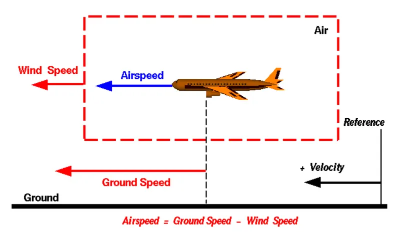
Wind Speed
For a reference point picked on the ground, the air moves relative to the reference point at the wind speed. Notice that the wind speed is a Vector quantity and has both a magnitude and a direction.
Ground speed- is the aircraft’s speed relative to the ground. One thing that should be noted here is that it’s its horizontal rather than vertical speed – an aircraft climbing completely vertically would have a ground speed of zero.Ground speed is also a Vector quantity
Airspeed- Airspeed is simply the speed at which an aircraft is moving relative to the air it is flying in. As such, it’s also the speed at which the air is flowing around the aircraft’s wings. If there is no wind, Airspeed is equals to ground speed.
Airspeed is the vector difference between the ground speed and the wind speed.
Airspeed = Ground Speed - Wind Speed
Q3)Why is it not recommended to use aircraft engine power to move it on the ground at Airport?
Solution:
It is recommended not to use aircraft engine power to move it on the ground at airport because when an aircraft's engine is activated, the thrust can create a high-speed wind that can easily cause damage to the airport terminal, surrounding ground vehicles, jetway, baggage and most importantly, ground personnel.
Suppressing the use of engines is especially important when towing a large aircraft, as their more powerful thrust capabilities can become exceedingly dangerous. Engine thrust can easily send any loose items airborne, turn the tiniest grains of dust into hazardous projectiles and create debris that can cause damage to multi-million dollar engines. Additionally, aircraft engines consume a great deal of fuel and generate extreme noise that can be harmful to ground personnel. Using a pushback tug for aircraft is simply a more economical and safer option than running the engines.
Q4) How an aircraft is pushed to runway when its ready to take off?
Solution:
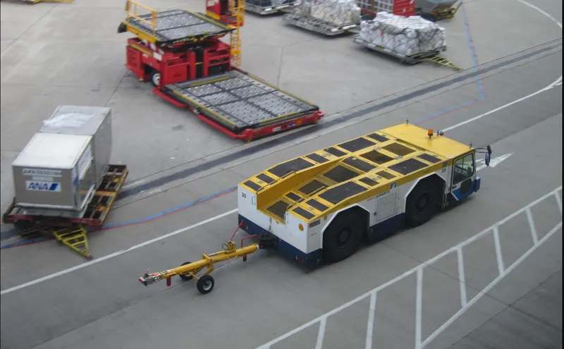
In aviation, pushback is an airport procedure during which an aircraft is pushed backward away from its parking position, usually at an airport gate by an external power. Pushbacks are carried out by special, low-profile vehicles called pushback tractors or tugs.
Although many aircraft are capable of moving themselves backward on the ground using reverse thrust (a procedure referred to as a powerback), the resulting jet blast or prop wash would cause increased noise, damage to the terminal building or equipment, and hurt airport staff due to high-speed debris. This debris would also be sucked into the engine, as it is in normal use, and cause excessive wear - a major cause of wear on aircraft engines is during ground use. A pushback is therefore the preferred method when ground-handling aircraft. The figure below shows the pushback of a aircraft with help of truck

Pushbacks at busy aerodromes are usually subject to ground control clearance to facilitate ground movement on taxiways. Once clearance is obtained, the pilot will communicate with the tractor driver (or a ground handler walking alongside the aircraft in some cases) to start the pushback. To communicate, a headset may be connected near the nose gear.
Since the pilots cannot see what is behind the aircraft, steering is done by the pushback tractor driver and not by the pilots. Depending on the aircraft type and airline procedure, a bypass pin may be temporarily installed into the nose gear to disconnect it from the aircraft's normal steering mechanism.
Once the pushback is completed, the towbar is disconnected, and any bypass pin is removed. The ground handler will show the bypass pin to the pilots to make it clear that it has been removed. The pushback is then complete, and the aircraft can taxi forward under its own power.
The figure below shows pushback tug with a towbar on the apron.
Q5)Learn about take off power, tyre design, rolling resistance, tyre pressure, brake forces when landing.
Solution:
Take off power
It’s the power setting for takeoff or we can say it is the amount of power that an engine is allowed to produce for a limited period of time for takeoff.
In a general aviation reciprocating engine, you set full power. In turbine engine aircraft you can set 100% power but have the option to set less than 100% based on weight and ambient conditions.Whatever power setting results from the instructions in the aircraft manual that tell you how to set power for takeoff under the prevailing conditions.
For light aircraft, usually full power is used during takeoff. Large transport category (airliner) aircraft may use a reduced power for takeoff, where less than full power is applied in order to prolong engine life, reduce maintenance costs and reduce noise emissions. In some emergency cases, the power used can then be increased to increase the aircraft's performance.
Tyre design and Construction
When it comes to safety, tyres are one of the most important components of aircraft. They help to absorb the shock of landing and provide cushioning. It also provides the necessary traction for braking and stopping of an aircraft.
An aircraft tyre is designed to withstand extremely heavy loads while landing, take off, taxing, and parking. The number of wheels required for aircraft increases with the weight of the aircraft, as the weight of the aeroplane needs to be distributed more evenly.
The figure below shows the construction nomenclature of an aircraft tire
Carcass plies are used to form the tire. They are sometimes called casing plies. An aircraft tyre is constructed for the purpose it serves.
- They support the weight of an aircraft while it is on the ground.
- It also provides the necessary traction for braking and stopping of an aeroplane.
- Tyre also helps to absorb the shock of landing and provide cushioning the roughness of takeoff, roll-out, and taxi operations.
Unlike an automobile or truck tyre, it does not have to carry a load for a long period of continuous operation. However, an aircraft tyre absorbs the high impact loads of landing, and also it’s operating at high speeds for a short time when required.
Some important terms regarding aircraft tyre,
Retreading – Retreading is methods of restoring a worn tyre by renewing the tread area or by renewing the tread area plus one or both sidewalls. Repairs are included in the tyre retreading process.
Load Rating – Load rating is the maximum permissible load at a specified inflation pressure.
Ply Rating – Ply Rating is used to identify the maximum recommended load rating and inflation pressure for a specified tyre. It is an index of tyre strength.
Speed Rating – The speed rating is the maximum takeoff speed to which the tyre has been tested.
Skid Depth – Skid depth is the distance between the tread surface and the deepest groove as measured in the mould.
Aircraft tyres must have an approved speed and load rating and have sufficient clearance when retracted through landing gear to allow for tyre growth. Tyre growth is the increase in the size of the tyre due to centrifugal forces at high speed.
Aircraft tyres may be Tube-type or Tubeless -Tubeless tyres are more advantageous over tube-type. There is no longer the use of tube-type tyre in recent aviation. Nowadays all airliners are using tubeless tyres. Tubeless that are meant to be used without a tube has the word TUBELESS on the sidewall of the tyre.
Aircraft tyres may be Radial or Bias-Almost all airliners are using Radial tyre. Bias is an older design, and it’s mainly used for road vehicles. Radial tyres have the word RADIAL on the sidewall. Radial tires are more expensive than bias-ply tyres. Radial tires are in demand because of their lower life cycle cost and long term value.
Rolling Resistance
The force that resists the motion of a body rolling on a surface is called the rolling resistance or the rolling friction.
When aircraft is towing or taxiing to push it into the runway or when takeoff roll is happening, the rolling resistance force act against the traction force of the aircraft.
This rolling resistance force depends on many factors like surface of the road, roughness of the road, dry or wet condition of the road, tyre pressure, tyre material, tyre temperature, thread pattern of the tyre etc, which determines the rolling resistance force.
The rolling resistance force will be given by the equation as :
F = μ*mg
Where,
μ = rolling resistance coefficient
m = total mass of aircraft
g = acceleration due to gravity
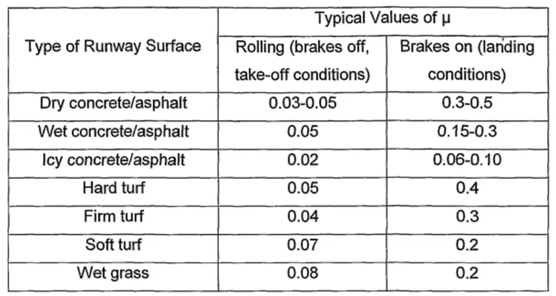
The figure below shows the value of rolling resistance coefficient for different surface
Tyre pressure
Tyres are the main contact point between the surface and the rest of the aircraft. The optimal performance of the aircraft depends on the health and maintenance of the tyres. One major factor that needs regular monitoring is the tyre pressure. Whether it is a tube or a tubeless tyre, without the right tyre pressure, you will be running on flats. Keeping proper tyre pressure helps the tyres last longer and helps improve the handling of the aircraft.
Aircraft tyre pressure depends on the aircraft, it varies from 30 psi to 250 psi depending upon the maximum gross weight of aircraft.
The tire pressure is inversly proportional to tyre rolling resistance.
Brake forces when landing
Aircraft brakes stop a moving aircraft by converting its kinetic energy to heat energy by means of friction between rotating and stationary discs located in brake assemblies in the wheels.
Brakes provide this critical stopping function during landings to enable airplanes to stop within the length of the runway. They also stop aircraft during rejected takeoff events, in which an attempted takeoff is canceled as the airplane is rolling down the runway before it lifts off from the ground due to engine failure, tire blowout, other system failure or direction from air traffic control.
Aircraft brakes also prevent motion of the aircraft when it is parked, limit its speed during taxiing and can even help steer the aircraft on the ground by applying different levels of braking force to the left- and right-side brakes.
The figure below shows a brake assembly on a Boeing 737NG main landing gear, visible after removal of one the wheels.
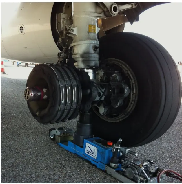
Aircraft brakes work in conjunction with other brake mechanisms such as thrust reversers, air brakes and spoilers. Thrust reversers are surfaces that are deployed into the path of the jet blast from the engines to redirect propulsive thrust in a direction that opposes the motion of the aircraft. Air brakes and spoilers are flight control surfaces that create additional aerodynamic drag when deployed into the path of air flowing around the aircraft.
Part B:
Q6-A) With necessary assumptions, calculate the force and power required to push / pull an aircraft by a towing vehicle.
Solution:
The force acting on the towing vehicle while push/pull the aircraft is Rolling resistance force and Aerodynamic drag force.
Rolling resistance force(Frr)
The force that resists the motion of a body rolling on a surface is called the rolling resistance or the rolling friction.
Rolling resistance Force(Frr) = urr * m * g
Where μrr.m.g">μrr = Rolling resistance co-efficient
m = Total mass of the vehicle(including pay load)
g = gravitational constant , that is 9.8 m/s^2
Aerodynamic drag force(Fad)
Aerodynamic drag is the force an object needs to overcome as it moves through air at a certain velocity.
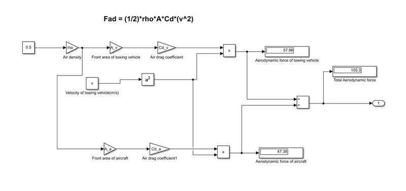
Aerodynamic drag force(Fad) = (1/2)*ρ*A*Cd*v^2
where, ρ = Air density, that is normally 1.25 kg/m^3
A = Frontal area of the towing vehicle in m^2
Here Cd = Cd_t + Cd_a
Cd_t Air drag co-efficient of towing vehicle
Cd_a = Air drag co-efficient of aircraft
v = Velocity of the vehicle in m/s
Here we need to calculate the force and power required to push / pull an aircraft by a towing vehicle. So we are assuming Aircraft is Airbus 320
Assumtion:
Weight of aircraft(Air Bus- A320 ) = 78000kg
Weight of towing vehicle = 10000 kg
Rolling Resistance Coefficient of an aircraft tire = 0.003
Rolling Resistance Coefficient of an towing vehicle = 0.02
The Velocity Towing Vehicle = 25 KMPH = 6.95 m/s
Density of Air medium = 1.25 kg/m3
The Frontal area of the Aircraft = 18 m^2
The Frontal area of the Vehicle = 3.2 m^2
The Coefficient of Drag of the Aircraft = 0.0872
The Coefficient of Drag of the Tugs tractor = 0.6
Air Bus - A320
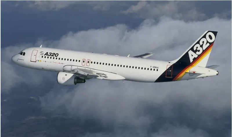
Maximum weight- 78000kg
Drag coeficient - 0.0872
Calculation
We know Frr = urr*m*g
Rolling Resistance Force of Towing vehicle = Frr_1 = 0.02*10000*9.8 = 1960 N
Rolling Resistance Force of aircraft = Frr_2 = 0.02*78000*9.8 =15288 N
Total Rolling Resistance Force = Rolling Resistance Force of aircraft + Rolling Resistance Force of Towing vehicle
Total Rolling Resistance Force = 17248 N
Aerodynamic drag force(Fad)
We know Fad = (1/2)*ρ*A*Cd*v^2
Assume ρ = 1.25 kg/m^3
The Aerodynamic Drag Force of the Aircraft = .5*1.25*18*0.0872*(6.95^2)= 47.38 N
The Aerodynamic Drag Force of towing vehicle = .5*1.25*3.2*0.6*(6.95^2) = 57.963N
Total Aerodynamic Drag Force = Air Drag Force of the Aircraft + Air Drag Force of the Tugs Tractor
Total Aerodynamic Drag Force = 105.343 N
Fad_total = 105.343 N
There fore, Total force (F_total) = Total Rolling resistance Force(Frr_total) + Total Aerodynamic drag force(Fad_total)
F_total = 17248 N + 105.343 N
F_total = 17353.343 N
Now, Power required to push/pull the aircraft:
Power = Total force * Velocity
Power = 17353.343 * 6.95
Power = 120605.733 W
Therefore Power = 120.605 kW
Q6-B. Develop the model for the calculated force and power using Simulink.
Solution:
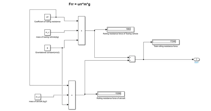
Here we are creating simulink for the calculation of total force and power with above details and the model is given below
Rolling resistance force
Aerodynamic drag force
Total Force and Power
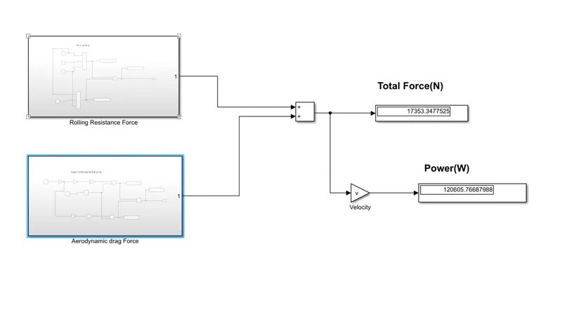
From the above model we understood that we get exact value as we calculated manually.
7. A. Design an electric powertrain with type of motor, it’s power rating, and energy requirement to fulfill aircraft towing application in Simulink. Estimate the duty cycle range to control the aircraft speed from zero to highest. Make all required assumptions. Prepare a table of assumed parameters. Draw a block diagram of powertrain.
Solution:
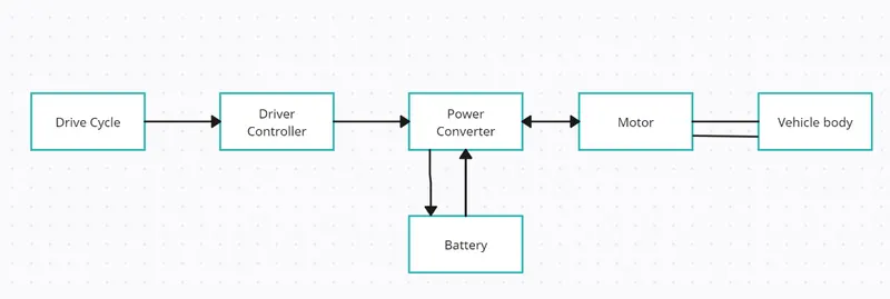
Block Diagram of powertrain:
Assumtion:
Weight of aircraft(Air Bus- A320 ) = 78000kg
Weight of towing vehicle = 10000 kg
Rolling Resistance Coefficient of an aircraft tire = 0.003
Rolling Resistance Coefficient of an towing vehicle = 0.02
The Velocity Towing Vehicle = 25 KMPH = 6.95 m/s
Density of Air medium = 1.25 kg/m3
The Frontal area of the Aircraft = 18 m^2
The Frontal area of the Vehicle = 3.2 m^2
The Coefficient of Drag of the Aircraft = 0.0872
The Coefficient of Drag of the Tugs tractor = 0.6
Towing time =20 min.
Motor efficiency = 93 %
Gear ratio efficiency = 95%
Tyre radius = 0.6 m
Gear ratio = 10
Battery power =200 kw
From the calculation done in 6-A
The total force required pull the aircraft is F_total = 17353.343 N
Power required to push/pull the aircraft = 120.605 kW
So we can write wheel axle torque = Force * radius of wheel
= 17353.343*0.6
= 10.412 KNm
Motor Torque Tm = Wheel axle torque/(Gear ratio*Gear ratio eff)
= 10.412 / (10*0.95)
Tm = 1.096KNm
We assume that motor efficiency is 93%
therefore required motor torque Tm_required = 1.096/0.93
Tm_required = 1.178KNm
There fore By considering all the efficiency , total power required by the motor is
Pm_required = 120.605 kW/0.95*0.93
Pm_required = 136.508 Kw
Therefore energy required for 20 min(0.3 hour) of towing is
Energy_required = 136.508*0.3 = 40.9524 Kwh
Let's assume power of the battery used in the towing vehicle is 200Kw
Therefore the duty cycle range to control the aircraft speed from 0 to 4m/s(maximum speed) is
Duty cycle = Required power/ rated power
Duty cycle = 136.508/200 = 0.62
So we can say that we can control the speed of the towing vehicle in the duty cycle range 0 to 62 %.
For this application an Induction motor or a BLDC can be used with a proper gear system.
Though a Induction motor has been choosed for this application but here this simulink model is built based on a DC motor.
Simulink Model
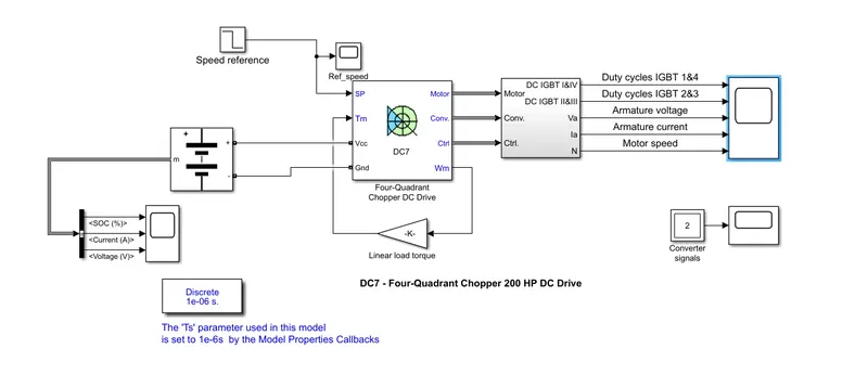
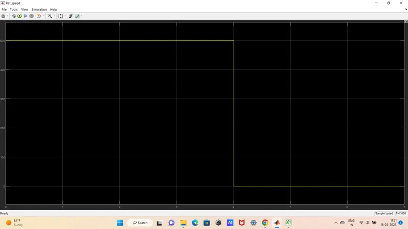
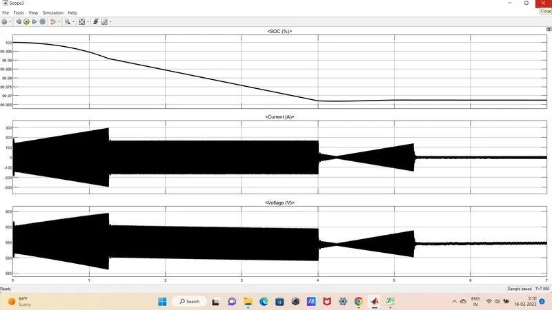
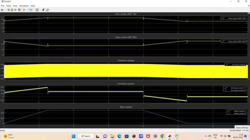
Response
7B-Design the parameters in excel sheet.
Solution: