Project-1: Powertrain for aircraft in runways
1.ANSWER
Aircraft gross weight:
The Aircraft Gross Weight is the total aircraft weight at any moment during the flight or ground operation. An aircraft's gross weight will decrease during a flight due to fuel and oil consumption. And may also vary during a flight due to payload dropping or in-flight refuelling. At the moment of releasing its brakes, the gross weight of an aircraft is equal to its takeoff weight. During flight, an aircraft's gross weight is referred to as the “in-flight weight” refuelling and at the moment of releasing its brakes, the gross weight of an aircraft is equal to its takeoff weight. During flight, an aircraft's gross weight is referred to as the en-route weight or in-flight weight.
Excessive weight reduces the efficiency of an aircraft and the available safety margin if an emergency condition should arise.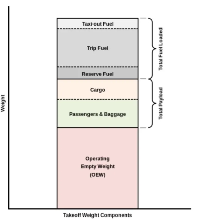
Maximum design taxi weight (MDTW):
The maximum design taxi weight is the maximum weight for aircraft navigating on the ground (taxiing or towing).
Maximum design takeoff weight (MDTOW):
It’s the maximum certificated design weight when the brakes are released for takeoff.
Maximum design landing weight (MDLW):
The maximum certificated design weight at which the aircraft meets the appropriate landing certification requirements. It generally depends on the landing gear strength or the landing impact loads on certain parts of the wing structure.
The MDLW must not exceed the MDTOW.
The maximum landing weight is typically designed for 10 feet per second (600 feet per minute).
Type MTOW [kg]
Antonov An-225 640,000
Scaled Composites Model 351 Stratolaunch 589,670
Airbus A380-800 575,000
Boeing 747-8F 447,700
Boeing 747-8 443,613
Boeing 747-400ER 412,770
Douglas DC-8-32 140,000
Tupolev Tu-154M 104,000
Bombardier Q400 28,000
ATR 42-500 18,600
BAe Jetstream 41 10,890
Learjet 75 9,752
Cessna Citation CJ4 7,761
2. ANSWER
Ground speed:
It is defined as the speed at which an object travels relative to a fixed point on the Earth's surface.
Wind Speed :
For a reference point picked on the ground, the air moves relative to the reference point . A positive velocity is defined to be in the direction of the aircraft's motion and a negative velocity is defined to be in the opposite direction of the aircraft.
Airspeed :
The important quantity in the generation of lift is the relative velocity between the object and the air, which is called the airspeed. Airspeed cannot be directly measured from a ground position, but must be computed from the ground speed and the wind speed. Airspeed is the vector difference between the ground speed and the wind speed.
The relationship between ground speed, airspeed, and wind speed can be written in the following form:
Vground = Vairspeed + Vwind
If the wind moves in the same direction as the aircraft, the term Vwind will have a positive sign. If the wind blows in the opposite direction as the plane's motion, Vwind will be a negative number.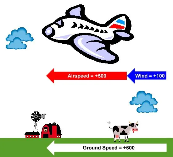
Let's assume that the aircraft speed is 500 kmph. However, the air itself is not motionless but moves at a speed of 100 kmph in this example. Let us also assume that the plane is traveling in the same direction as the wind such that it experiences a tailwind of 100 kmph. Since the wind and vehicle both move in the same direction, their velocities add together, and the ground speed becomes 600 kmph.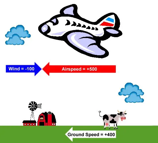
In this example, the wind still blows at the same speed with respect to the ground, but its direction is reversed. Now the plane travels against the wind and experiences a headwind of 100 kmph. The aircraft is still moving at the same cruise speed of 500 kmph with respect to the air, but the difference in the direction of motion of the air means that the wind speed must be subtracted from the plane's airspeed in order to determine the ground speed. The ground speed now becomes only 400 kmph.
3.ANSWER
The thrust to propel the aircraft forward comes from its propellers or jet engines.The pilot controlling the direction travelled with their feet. The use of engine thrust near terminals is restricted due to the possibility of jet blast damage. This is why the aircrafts are pushed back from the buildings by a vehicle before they can start their own engines for taxiing.
Aircraft can move using their own engine power all the time on the airport and taxiways,go towards runways and after landing taxi to their assigned gate. But the thrust produced resulting jet blast might cause damage to the terminal building or equipment.
Engines close to the ground may also blow sand and debris and then suck them into the engine and causing damage to the engine. And also it can reduce the cost for fuel.
Taxiing can save money.
Effectively a loss of control can happen, especially during high power engine running.
• There is a risk of injury to ground support personnel who may be in relatively close proximity to the aircraft.
• It is easier for truck driver to see the surroundings better than the pilot sitting in the cockpit with limited window. The pushback driver knows the airport better than the pilot.
• The plane engines are very loud. When more than one plane will add up their sound, than it will not be pleasent for passangers and others near airport.
4.ANSWER
The aircrafts always moves on the ground following the yellow lines, to avoid any collision with the surrounding buildings, vehicles or other aircrafts. The taxiing motion has a speed limit. Before making a turn, the pilot reduces the speed further to prevent tire skids. Just like cars, there is a certain list of priorities during taxiing. The aircrafts that are landing or taking off have higher priority. The other aircrafts have to wait for these aircrafts before they start or continue taxiing.
The thrust to propel the aircraft forward comes from its propellers or jet engines. Steering is achieved by turning a nose wheel or tail wheel/rudder; the pilot controlling the direction travelled with their feet. The use of engine thrust near terminals is restricted due to the possibility of jet blast damage. This is why the aircrafts are pushed back from the buildings by a vehicle before they can start their own engines for taxiing.
Take-Off:
Takeoff is the phase of flight in which an aircraft goes through a transition from moving along the ground (taxiing) to flying in the air, usually starting on a runway.
Generally The engines are run at full power during takeoff. Following the taxi motion, the aircraft stops at the starting line of the runway. Before takeoff, the engines (particularly piston engines) are routinely run up at high power to check for engine-related problems. This makes a considerable noise.
When the pilot releases the brakes, the aircraft starts accelerating rapidly until the necessary speed for take-off is achieved.
The takeoff speed required varies with air density, aircraft weight, and aircraft configuration.
The speeds needed for takeoff are relative to the motion of the air (airspeed). A head wind will reduce the ground speed needed for takeoff, as there is a greater flow of air over the wings. This is why the aircrafts always take off against the wind. Side wind is not preferred as it would disturb the stability of the aircraft. Typical takeoff air speeds for jetliners are in the 130–155 knot range.
For a given aircraft, the takeoff speed is usually directly proportional to the aircraft weight. as the heavier the weight, the greater the speed needed.
At the beginning of the climb phase, the wheels are retracted into the aircraft and the undercarriage doors are closed. This operation is audible by the passengers as a noise coming from below the floor.
Climb:
A climb is carried out by increasing the lift of wings supporting the aircraft until their lifting force exceeds the weight of the aircraft. Once this occurs, the aircraft will climb to a higher altitude until the lifting force and weight are again in balance. The increase in lift may be accomplished by increasing the angle of attack of the wings, by increasing the thrust of the engines to increase speed (thereby increasing lift), by increasing the surface area or shape of the wing to produce greater lift, or by some combination of these techniques. In most cases, engine thrust and angle of attack are simultaneously increased to produce a climb.
Cruise:
It occurs between ascent and descent phases and is usually the majority of a journey. Technically, cruising consists of heading (direction of flight) changes only at a constant airspeed and altitude. It ends as the aircraft approaches the destination where the descent phase of flight commences in preparation for landing.
Landing:
Landing is the last part of a flight, where the aircraft returns to the ground. Aircraft usually land at an airport. Landing is accomplished by slowing down and descending to the runway. This speed reduction is accomplished by reducing thrust and inducing a greater amount of drag using flaps, landing gear or speed brakes.
5. ANSWER
(A) Take Off Power:
The power required by the aircraft engines to use to lift them into a horizonatal takeoff is known as takeoff power. Usually this term is also known as takeoff thrust.
Take off power can be predicted using a simple measure of the acceleration of the aircraft along the runway based on force equilibrium.
The forces involved will be.
m*(dv/dt)=T-D-F
where,
dv/dt is the acceleration along the runway and m is the mass of the vehicle.
T is Thrust of propulsion system pushing aircraft along the runway.
D is Aerodynamic Drag of vehicle resisting the aircraft motion.
F is Rolling resistance friction due to the contact of wheels or skids on the ground.
During the take-off run, the imbalance in these forces will produce an acceleration along the runway.
The procedure for take-off will be that the vehicle will accelerate until it reaches a safe initial flying speed. The pilot can then rotate the vehicle to an attitude to produce a climb lift and it will ascend from the ground. The determination of this safe flying speed or rotation speed. V, is a critical factor in determining take-off performance. Take-off rules vary slightly depending on the aircraft category.
For Small commuter aircraft
V= 1.1*Vstall
or
V=1.05*V Control
Vstall≡(√W/0.5Clmax*ρS)
where S-Runway length
Take Off power = force*displacement
(m⋅dv/dt)⋅2⋅S1⇒(T−D−F).S1
(B) Tyre Design:
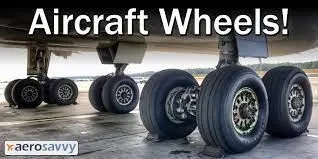
Designing aircraft tires is a very intense undertaking The tyre is designed to withstand heavy loads while landing, take off, taxing, and parking. The number of wheels required for aircraft increases with the weight of the aircraft, as the weight of the aeroplane needs to be distributed more evenly. Aircraft tyre generates more heat during landing Aircraft drags the wheel until they match the rotational velocity of wheels. Due to this heat generates. Aircraft's tread pattern is designed to facilitate stability in high crosswind conditions, to channel water away to prevent hydroplaning and for braking effect.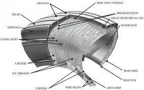
(C) Rolling Resistance:
Rolling resistance is the force resisting the motion when a body (such as ball, tyre or wheel) rolls on a surface. Rolling resistance can be seen in the aircraft when the aircraft takes-off from the runway & while landing at the runway with the help of their wheels.
Rolling resistance can be expressed as
Frr = μrr⋅m⋅g(N)
Where
Frr is the Rolli resistance(N)
μrr is coefficient of rolling resistance.
m is mass (kg)
g is acceleration due to gravity = 9.81m/s^2
(D) Tyre pressure:
Aircraft tyres operate at such high extremes of pressure, load, and speed, their care and service is critically important. The most important action an operator can take to prevent tyre-related events is to maintain proper tire inflation pressure. Aircraft tires are usually inflated with nitrogen to minimize expansion and contraction from extreme changes in ambient temperature and pressure experienced during flight. Dry nitrogen expands at the same rate as other dry atmospheric gases (normal air is about 80% nitrogen). but common compressed air sources may contain moisture, which increases the expansion rate with temperature.
(E) Brake Forces When Landing:
All The commercial aircraft have automatic brake systems. Juat like a car, these systems also have Anti-Lock Braking System(ABS) that prevents the tires from sliding down a wet runway. The advantage of the automatic brake system is that the aircraft brakes comfotably at a constant deceleretion. Pessengers experience a constant force that presses them into their seats. The brake system automatically applies the wheel brakes just enough to create a constant deceleration independent of the air resistance, spoilers and reversers. It is only in the last phase of brakes by pressing on both brake pedals. This deactivates the automatic brake system. Immediately after landing, the aircraft is still moving fast enough that aerodynamic devices are much more efficient that the brakes.
The brake units are powered by the hydraulics system. An electrical signal is sent from the flight deck to hydraulic actuators near the main landing gear. Here, hydraulic fluid at 3,000 pound per square inch is used to force the brake unit against the wheel, thus slowing it down.
When landing on slippery runways, there's a chance that the wheels may start to skid as the brakes are applied. To stop this from happening and to maintain maximum effective braking, each wheel has anti-skid protection.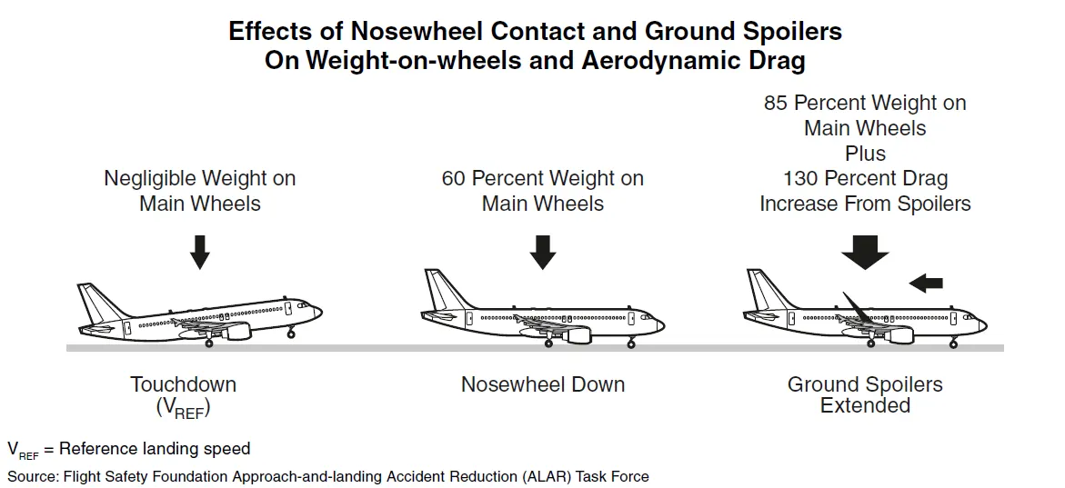
Following braking devices are used to decelerate the aircraft -
1. Spoilers.
2. Wheel Brakes (Including Anti-Skid systems & Auto-Brake systems).
3. Reverse Thrust
6. (A) ANSWER
Let us Assume:
Weight of the Aircraft (Airbus A-380) = 575000kg
Rolling Resistance Coefficient of an aircraft tire (μrr) = 0.002
Wight of the Towing Tractor = 1000kg
Rolling Resistance Coefficient of Towing Vehicle (μrr) = 0.002
Then,
Rolling Resistance Force of Tow Tractor = μrr×m.g = 0.002 × 1000 × 9.81 = 19.62 KN
Rolling Resistance Force of aircraft = μrr×m.g= 0.002 × 575000 × 9.81 = 11.281 KN
Total Rolling Resistance Force = Rolling Resistance Force of aircraft + Towing Tractor = 19.62+11.28
So Total Rolling Resistance Force = 30.90 KN
Air Drag Force-
The drag force is the force that occures due to the Air Strike effect on the vehicle when it moves. The vehicle moves through a air medium of particular dencsity value with certain speed this causes the air strike against the vehicle body and it causesDrag Force on the vehicle.
The Aerodynamic Drag is given by the following expression-
Fad=1/2⋅ρ⋅A⋅V^2⋅Cd
Where,
ρ= Density of Air Medium
A = Frontal Area Of the Vehicle which strike the Air
V = Velocity with the vehicle moves
Cd= Coefficient of Dragwhich varies different shapes of the frontal area.
Calculation:
Let us assume
The Velocity of the Aircraft while Towing = 14.5KMPH=4 m/s
Density of Air medium (ρ) = 1.225 kg/m^3
The Frontal area of the Aircraft = 150 m2
The Coefficient of Drag of the Aircraft = 0.025
Air drag force = 0.5*rho*A*V^2*Cd = 33.75KN
The Air Drag Force of the Aircraft = 33.75KN
Therefore the total force that the motor needs to overcome = Rolling Resistance of the aircraft + Drad Force Acting on the Aircraft hence the total forces acting = 30.90+33.75 KN= 64.65 KN
The Power Required-
The power required by the motor is given by the velocity with which the towing operation takes place.
The average speed of push/pull = 20 kmph = 5.5m/s
Power required by the motor = Total Force*Velocity = 64.65*5.5
Power Required by The Motor = 355.025 kw
6.B .ANSWER
SIMULINK MODEL: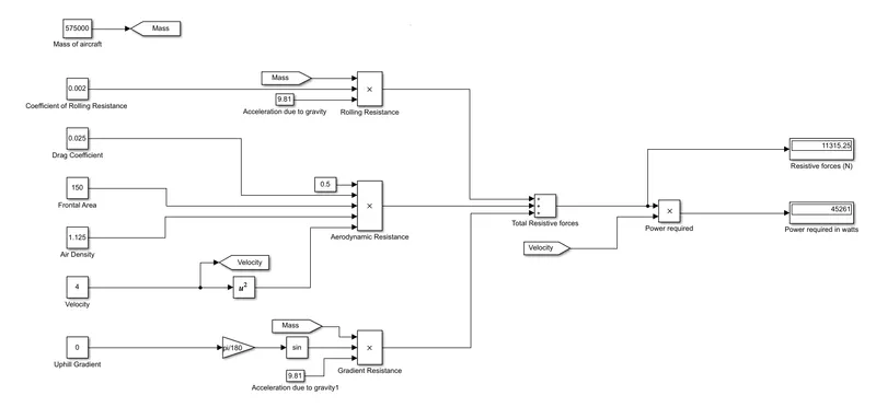
• constant blocks are used to feed the parameters such as mass, coefficients and other parameters
• using product block the resistive forces are calculated.
• using sum block, total resistive forces can be calculated.
• the outputs are visualised using display blocks.
7.ANSWER
The parameters assumed for designing this vehicle is taken from online references
S.No. Assumed Parameters Assumed Values
1. Weight of the Aircraft 575000 kg
2. Weight of the Towing Tractor 50000 kg
3. Rolling Resistance Coefficient of Aircraft 0.004
4. Rolling Resistance Coefficient of Towing Tractor 0.001
5. The velocity of the Aircraft while Towing 8.33 m/s
6. Density of Air medium(rho) 1.225 kg/m^3
7. The Frontal area of the Aircraft 20 m^2
8. The Coefficient of Drag of the Aircraft 0.026
9. Towing Tractor Gear ratio(G- for high torque output) 11
10. Towing Tractor tyre radus(r) 0.635 m
11. Operational time of the Towing for one cycle 0.33 Hour
12. The Battery Armature Voltage 350 V
13. The Battery Armature Current 350 A
14. The Motor Terminal Voltage for full power output 630 V @ motor terminals
15. Power converters used Bidirectional DC-DC Boost Converter
16. The maximum duty ratio for acieving full power 70%
Assuming the operational time of the Towing Truck is around 20 minuts for one cycle
20 minuts = 0.33 hour
Energy(kwh) = power(kw)*Time(h) = 162.8*0.33
Energy(kwh) = 41.8 kwh
Therefore the battery must be able to store the energy 41.8 kwh and should deliver the energy throughout the run time in order for the motor to produce the 1.32 KNm of torque instantaneously. Thus the storage of energy in batteries with high performance Ultracapacitors are selected to fulfill the required power deliver.
Motor Selection:
Here we have selected a BLDC Motor type that has a power rating of 126.8kw and with the gear ratio and the transmission it should be able to deliver 1.32KNm of torque instantaneously.
The Battery Armature Voltage (V) 350 V
The Battery Armature Current (A) 350 A
Power Converter:
A boost converter (step-up converter) is a DC-to-DC power converter that steps up voltage (while stepping down current) from its input (supply) to its output (load). It is a class of switched-mode power supply (SMPS) containing at least two semiconductors (a diode and a transistor) and at least one energy storage element: a capacitor, inductor, or the two in combination. To reduce voltage ripple, filters made of capacitors (sometimes in combination with inductors) are normally added to such a converter's output (load-side filter) and input (supply-side filter).
Speed Control of the Vehicle:
The Electric Vehicle uses power from the battery source to drive the motor and then further to drive the wheels in order to move the vehicle. The speed and torque generated from the motor is very important to drive the vehicle as per the driver's desire. If we connect the battery directly to the motor the motor will spin with a speed and torque characteristics which will be based on the full power of the battery voltage. We does not require full power in all the driving conditions so we need to adopt a power controller between the bettery and the motor so that the motor speed may be controlled by the driver to drive the vehicle as desired. For controlling the vehicle power we use the soft switching operation technique here. The amount of power can be controlled by changing the Duty Cycle value. Considering the losses we take 70% of the duty cycle to deliver the maximum power of the motor.
Motor Terminal Voltage = Armature Voltage * Duty Cycle = 900*0.7
With 70% Duty Cycle the voltage at motor terminals = 630V, Which gives the full power with all the gearings instantaneously. Thus by varying the Duty Cycle value the speed of the vehicle is controlled.
BLOCK DAIGRAM :
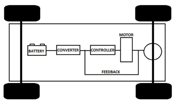
Simulink model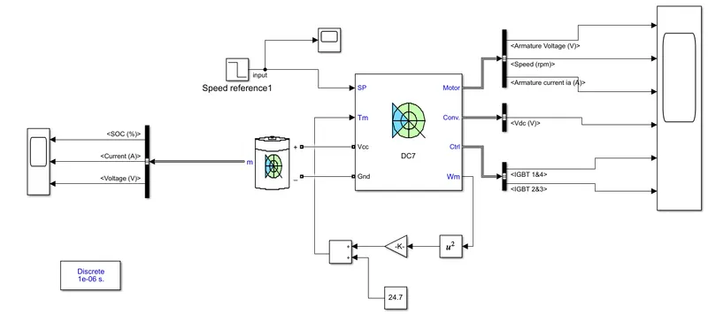
RESULT:
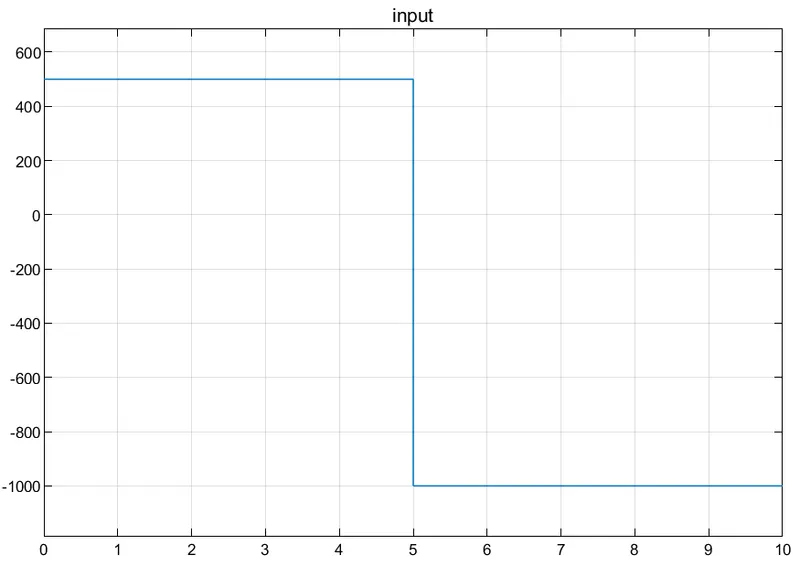
INPUT:
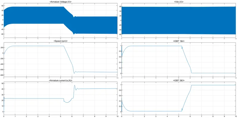
OUTPUT:
FOR MOTOR:
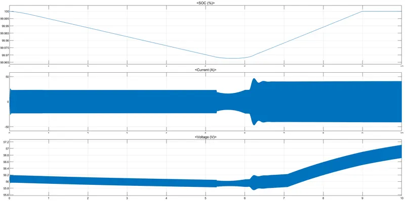
FOR BATTERY:
7.(B) MENTIONED IN TO ATTACHMENT SECTION