Week-7 Challenge: DC Motor Control
1 (A) ANSWER.
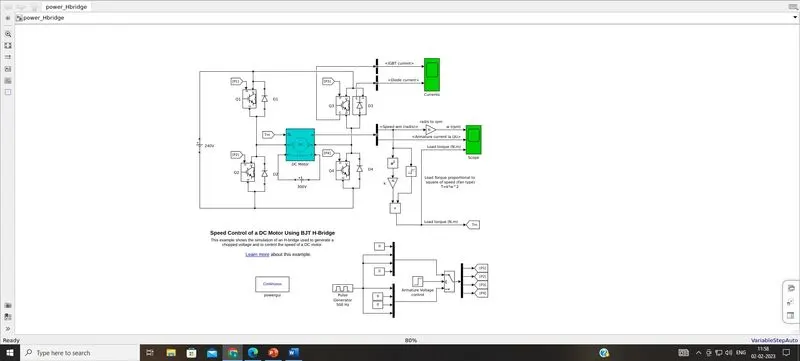
At first,run the speed control model of a DC motor using BJT H-bridge in matlab.We get a simulink window of the model as shown below.
MODEL EXPLANATION:
- DC motor used parameter are (5 HP 24V 1750 rpm).
- It simulates a fan type load (where Load torque is proportional to square of speed). The armature mean voltage can be varied from 0 to 240 V when the duty cycle (specified in the Pulse Generator block) is varied from 0 to 100%.
- The H-bridge consists of four BJT and Diode pairs.
- Two transistors are switched simultaneously: Q1 and Q4 or Q2 and Q3.
- When Q1 and Q4 are fired, a positive voltage is applied to the motor and diodes D2-D3 operate as free-wheeling diodes when Q1 and Q4 are switched off.
- When Q2 and Q3 are fired, a negative voltage is applied to the motor and diodes D1-D4 operate as free-wheeling diodes when Q2 and Q3 are switched off.
SIMULATION RESULT :
Speed of motor:
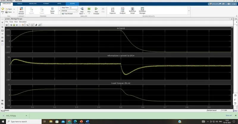
- Initially increases to 0 to nearly 900 rpm upto 0.5 secs(Forward motoring zone).
- Then speed reduces to 0 rpm(Forward dynamic breaking zone).
- Then speed increases from 0 to -900 rpm at upto 1 sec( Reverse motoring zone).
Load torque of motor:
- Initially torque increase from 0 to 0.5 secs in forward motoring action.
- Then torque reduces to 0 Nm in forward dynamic breaking zone.
- Then torque increases in reverse direction in reverse motoring action upto 1 sec.
Armature current shoot up in motor.
from armature current graph , we can see that ,at starting there is sudden spike increase in current at 0 sec also and at 0.5 sec also.In this transition of positive to negative direction of rotation we observe a high surge in current, this is due to the transient switching occurring in the circuit.
(B) ANSWER
Armature current shoot up in motor.
Here the initial current shoot up is due to sudden increase in voltage.In this case motor driven in 75% of duty cycle tht mean 0.75*240= 180 V.
The surge in the current can be reduced by reducing the duty cycle. In above results , the duty cycle selected as 75%.
by changing the duty cycle from 75% to 50% , the current surge can be reduced tremendously.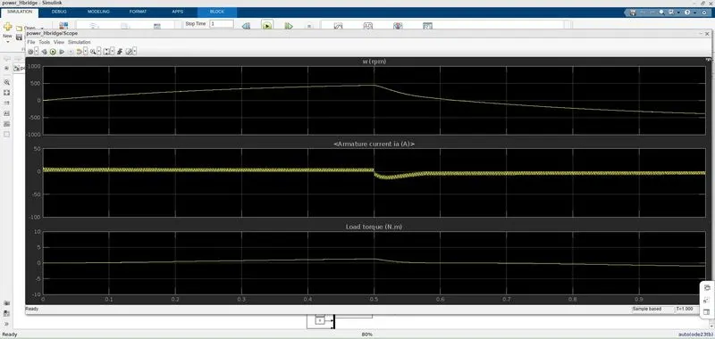
Thus we can find that,the armature curent spike is reduced by changing the duty cycle from 75% to 50%.Sudden shoot up canceled in starting condition but there is a slight shootup after 0.5 sec in reverse motoring condition.
Again changing duty cycle to say 35%,we get the result as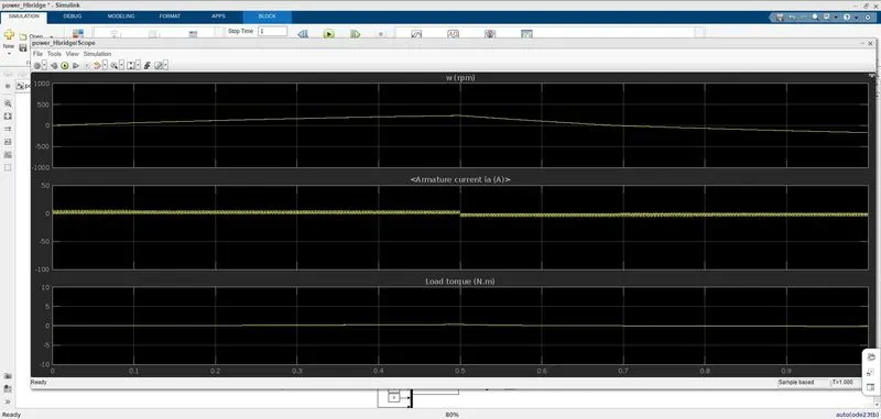
The shoot up of current get dimlished on both the ends.
Conclusion:
Thus to reduce the shootup armature currents we have to change the duty cycle gradually from 0 to 100%,that inturns increases voltage gradually and speed also changes accordingly.
(C) ANSWER
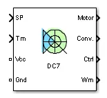
Figure : (DC7) block
INPUT : Armature voltage ,speed referance ,motor torque referance.
OUTPUT :Motor,convertor,controller,
Working:
• Here Four IGBT switches are used.
• Here pulses are given from PI current controller, that controles the pulses by comparing armature current measurement and current referance.
• Current referance can be generated by using regulation switch in that torque referance and PI speed controller pulses,that internally compared by speed of motor and refrance speed given as input.
• Mainly speed controlled by current controller.
• In this case Four quadrant operations are performed.
• Forward motoring mode,forward regenerative breaking mode: Q1,Q4 are on and Q2,Q3 are in off.
• Reverse motoring mode,reverse regenerative breaking mode: Q2,Q3 are on and Q1,Q4 are in off.
Comparisons with H-bridge :
• In DC7 chopper model speed controlled by varying current pulses from PI current controller and in H-brige model speed controlled by varying duty cycles voltages.
• Here regenerative breaking in occring while in H-bridge model breaking is occured by changing polarity of current flow,dynamic breaking occurs in it.
• In four quadrant DC chopper model smoothing inductance is used for smooth increase and decrease in current flow which inturns controlling the motor speed smoothly,while in
• H-bridge it is not present.
• Here the operation is discreat and in H-bridge model it is continuous.
• Hence 4 quadrant DC choppers are used mostly in electric vehicles.
2. ANSWER
Where,
Vs=DC voltage source.
CH1= Power electronic switch 1.
CH2= Power electronic switch 2.
D2,FD = Free wheeling diodes.
L=Inductor load.
E Back emf from load.
Mode of operation:
• Here either one should be ON at a time,either CH1 or CH2.
• If CH1 is ON the current flows from source +ve to load(here DC motor),passes through L and E to -ve terminal of source.(1st quadrant)
• If CH1 is OFF the, FD diode conducts and complete the circuit (L-E-FD-L) as stored energy in inductor L.The voltage across is also positive voltage,current direction also positive.
• Now If CH2 is ON,Current flow from E(Load current) completes the circuit(L-CH2-E).
• If CH2 gets OFF,the current passes through D2 towards source completes the circuit(E-L-D2-+ve source- -ve source-E).
• In this stage regenerative breaking occurs.(2nd quadrant).
• This cycle continuous again upto stop time.
SIMULATION MODEL :
DC voltage source 24v.
Duty cycle 50%.
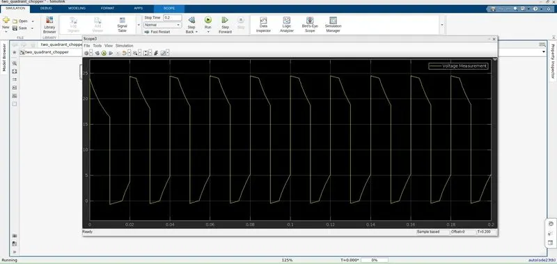
DC voltage across load 12v.
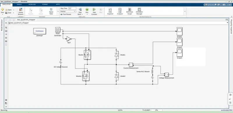
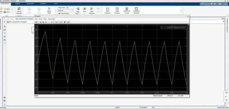
Simulation Result:
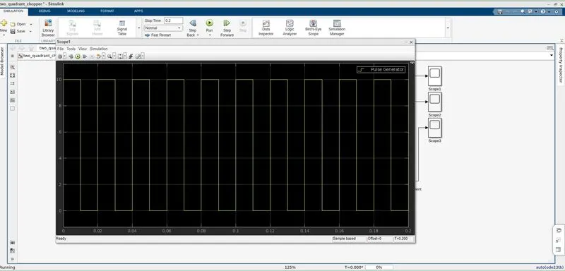
PWM
VOLTAGE
CURRENT
3. ANSWER
Brushless DC motor (BLDC)
A brushless DC motor (known as BLDC) is a permanent magnet synchronous electric motor which is driven by direct current (DC) electricity and it accomplishes electronically controlled commutation system instead of a mechanically commutation system. BLDC motors are also referred as trapezoidal permanent magnet motors.
Working Principle and Operation of BLDC Motor
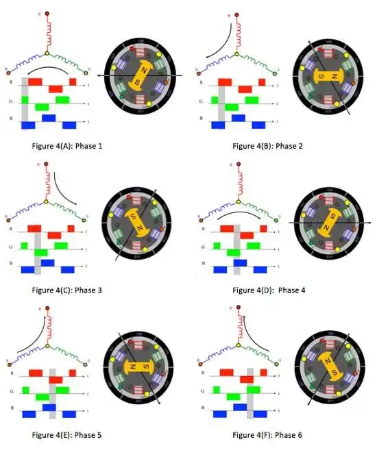
BLDC motor works on the principle similar to that of a conventional DC motor, i.e., the Lorentz force law which states that whenever a current carrying conductor placed in a magnetic field it experiences a force. As a consequence of reaction force, the magnet will experience an equal and opposite force. In case BLDC motor, the current carrying conductor is stationary while the permanent magnet moves. When the stator coils are electrically switched by a supply source, it becomes electromagnet and starts producing the uniform field in the air gap. Though the source of supply is DC, switching makes to generate an AC voltage waveform with trapezoidal shape. Due to the force of interaction between electromagnet stator and permanent magnet rotor, the rotor continues to rotate
BLDC over Brushed dc motor
Brushless DC motors typically have an efficiency of 85-90%, while brushed motors are usually only 75-80% efficient. Brushes eventually wear out, sometimes causing dangerous sparking, limiting the lifespan of a brushed motor. Brushless DC motors are quiet, lighter and have much longer lifespans. Because computers control the electrical current, brushless DC motors can achieve much more precise motion control.
Because of all these advantages, brushless DC motors are often used in modern devices where low noise and low heat are required, especially in devices that run continuously. This may include washing machines, air conditioners and other consumer electronics. They may even be the main power source for service robots, which will require very careful control of force for safety reasons.
Brushless DC motors provide several distinct advantages over other types of electric motors, which is why they’ve made their way into so many household items and may be a major factor in the growth of service robots inside and outside of the industrial sector.