Project-1: Powertrain for aircraft in runways
P r o j e c t -1 :
Powertrain for Aircraft in Runways :
------------------------------------------------------------------------------------------------------------
Part A:
1. Search and list out the total weight of various types of aircrafts.
2. Is there any difference between ground speed and air speed?
3. Why is it not recommended to use aircraft engine power to move it on the ground at Airport?
4. How an aircraft is pushed to runway when its ready to take off?
5. Learn about take off power, tyre design, rolling resistance, tyre pressure, brake forces when landing.
Part B:
6. A. With necessary assumptions, calculate the force and power required to push / pull an aircraft by a towing vehicle.
B. Develop the model for the calculated force and power using Simulink.
7. A. Design an electric powertrain with type of motor, it’s power rating, and energy requirement to fulfill aircraft towing application in Simulink. Estimate the duty cycle range to control the aircraft speed from zero to highest. Make all required assumptions. Prepare a table of assumed parameters. Draw a block diagram of powertrain.
B. Also, Design the parameters in excel sheet.
------------------------------------------------------------------------------------------------------------
|{ PART [A] }|
__________________________________________________________________________________________________________________________________
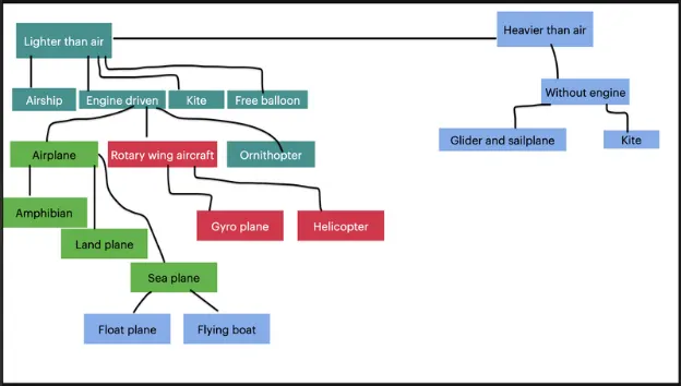
Aim #1. Search and list out the total weight of various types of aircrafts.
Aircraft
|
Lighter than Air (Aerostat) |
Heavier than Air (Aerodyne) |
|
Any aircraft kept aloft by a gas which are lighter than air falls under this category. |
Aerodyne is the technical name for any type of heavier than air aircraft. This covers all the aircraft that derives flight in principally with the aerodynamic forces. |
Lighter than Air Aerostat)
|
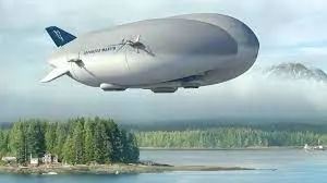
Airship |
Free Balloon |
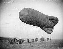
kite Balloon |
|
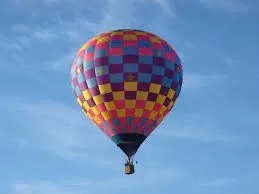
These are Aerostats having powerplant propulsions and means of steering the craft. They are made of buoyant by enclosing a volume of gas lighter than air. Here the internal pressure of the gas helps to maintain the shape of the envelope without the need of any longitudinal members. Weight: 1600 kg
|
These are balloons which are not anchored to the ground and are
|
These are balloons which are shaped and trimmed so as to derive stability from wind. |
Heavier than Air (Aerodyne)
|
Engine Driven |
Without Engine |
|||
|
Airplane |
Rotary Wing Aircraft |
Ornithopter |
Glider & Sailplane |
Kite |
|
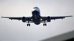
This is an engine driven aerodyne that achieves lift from the dynamic action of air against fixed wings.
|
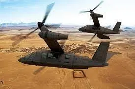
This is an engine driven aerodyne that achieves lift from the dynamic action of air
|
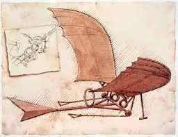
This is an engine driven aerodyne that achieves lift from the dynamic action of
|
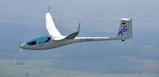
This is an aerodyne which flies without any applied power due to aerodynamic lift generated by its wings and initial thrust given by some launching mechanism and weighs around 150-200 kgs.
|
|

Airplane
|
Amphibian |
Land plane |
Sea plane |
|
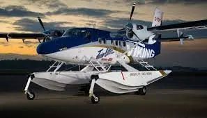
They can take off and land on both land & sea surface. SEASTAR WORLD'S MOST ADVANCED AMPHIBIOUS AIRCRAFT This is the example of Amphibious flight "Sea Star" and weighs around 5150 kg.
|
They can take off and land only on the land surface. Most of the commercial and the military flights come under this. This is the example of commercial flight "Boeing 747" and weighs around 448 ton. 24.5 TONNES 40.00m 5.30 M mal load 9.5 TONNES Fuel (internal) 4.7 TONNES UP TO 67 TONNES 15.30 M• This is the example of defence flight "Rafale" and weighs around 24.5 tonne.
|
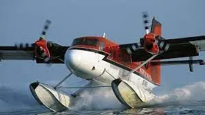
They can take off and land only on sea surface. This is the example of Sea plane flight "Cessna 172E" and weighs around 1050 kg.
|
Rotary wing aircraft
|
Gyroplane |
Helicopter |
|
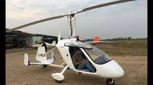
This is a power driven aerodyne which derives lift mainly from a rotor freely rotating in the horizontal plane, but thrust is obtained from a conventio This is the example of Gyroplane "Auto Gyro Calidus" and weighs around 450 kg. nal engine.
|
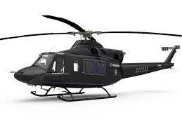
This is an aerodyne which derives both lift and thrust from rotating rotors. This is the example of Helicopter "Mi 26" and weighs around 22 tons.
|
__________________________________________________________________________________________________________________________________
Aim : 2. Is there any difference between ground speed and air speed?
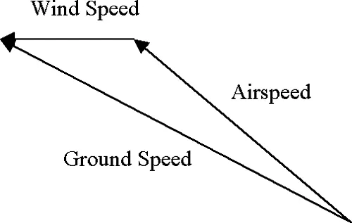
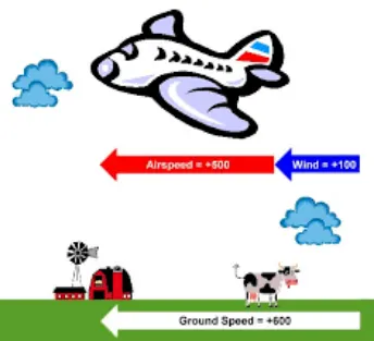
With reference to the above image, I'm going to differentiate the ground speed and the airspeed. Ground speed is the aircraft speed relative to the ground that it explains how speed can aircraft travel in the ground.
It is not dependent on the airspeed. Here Airspeed is the relative motion between the object and the air. This is also an important parameter for aerodynamic lift generation.
This air speed of the object cannot be measured directly from the ground, it depends upon the ground and the wind speed, in fact it is the "vector difference" between the ground and wind speed.
(As shown in the above figure). On a perfectly still day, the airspeed is equal to the ground speed. But if the wind is blowing in the same direction that the aircraft is moving, the airspeed will be less than the ground speed.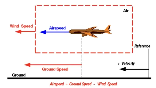
__________________________________________________________________________________________________________________________________
Aim #3 :. Why is it not recommended to use aircraft engine power to move it on the ground at Airport?
"Taxiing" refers to the aircraft movement while on the ground under its own power. This term excludes the accelerating run before takeoff and the decelerating run after landing. The jet engine used is generally not preferred as the primary thrust for taxiing because a large amount of fuel is wasted while the aircraft is still on the ground which could have been used for flying. Since the cost of fuel is one of the biggest expenses in the airline business, many companies are planning to switch to electric taxiing to save fuel and reduce emissions.
There are 2 more important reasons,
i) If the high mounted engines are powered there is a huge risk of the jet blast which may affect the surrounding building and the environment.
li) In case of low mounted engines are turned on there is a higher possibility of any gravel or other impurities lying in the ground may enter the engine and damage it.
Here is where Pushback trucks & Electric taxiing systems use electric motors fitted inside the wheels of the aircraft's landing gear. Electric power is supplied to these motors by an onboard Auxiliary Power Unit (APU). This innovative new approach enables airplanes to move backward and forward solely under electric power. This way, aircraft can avoid reliance on main engines for traversing the airport taxiways while burning fuel unnecessarily.
__________________________________________________________________________________________________________________________________
Aim#4 : . How an aircraft is pushed to runway when its ready to take off?
As explained in the previous answer, "Taxiing" refers to the aircraft movement while on the ground under its own power. This term excludes the accelerating run before take-off and the decelerating run after landing.
So we know the repercussions that might occur when the engine is used on the runway. So Pushback seemed to be a widely popular option for rolling the aircraft on the runway.
Airplanes fly because they are able to generate a force called Lift which normally moves the airplane upward. Lift is generated by the forward motion of the airplane through the air. This motion is produced by the Thrust of the engine(s).
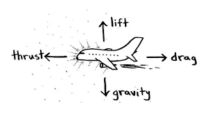
The figure below is a simple diagram of the four forces acting on an airplane – Thrust, Lift , Drag and Weight. Drag is the force produced by the resistance of the air to the forward motion of the airplane. Swish your hand rapidly side-to-side and you will feel that resistance on your hand.
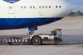
Pushback means the movement of an aircraft from nose-in parking stand using the power of a specialized ground vehicle attached to or supporting the nose landing gear. Conventionally a tow bar is a link used between the aircraft and Pushback tug. Since the pilots have limited vision from the cockpit what lies behind & side of the aircraft, most of the steering will be done by the driver in Pushback.
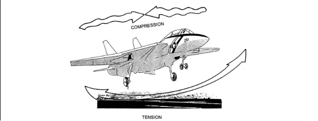
There are certain factors that is needed to be kept in mind before the aircraft is ready to take-off, it must go through various praparatory pre-takeoff procedures. Among the things that happen to a plane before its boarded and ready to take-off includes:
Restocking the plane with food and necessary items for its next flight.
Cleaning the plane for make it ready for the next flight; this can be quick cleaning job if the plane is doing several flights back to back, or a more thorough one once its itinerary is completed.
Check of onboard systems to see if there is anything that needs to be repaired or monitor.
Refueling
Pushback and getting the plane in position for its next flight.
Preflight checks, boarding and asking for clearence for take-off.
__________________________________________________________________________________________________________________________________
Aim #5: Learn about take off power, tyre design, rolling resistance, tyre pressure, brake forces when landing.
Take-off power: It is the phase where the flight leaves the ground and becomes airborne. Take off performance can be predicted using a simple measure of the acceleration of the aircraft along the runway
based on force equilibrium.
The forces involved will be,
T- Thrust of propulsion system pushing aircraft along runway.
D- Aerodynamic Drag of vehicle resisting the aircraft motion.
F- Rolling resistance friction due to the contact of wheels or skids on the ground.
During take-off run the imbalance in these forces will produce an acceleration along the runway
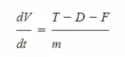
where dv/dt is the acceleration along the runway and m is the mass of the vehicle.
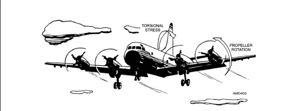
Rolling resistance:
The friction between aircraft and runway will be proportional to the normal force exerted by the aircraft on the runway.
F=u(W-L)
The normal force will be the difference between Weight of aircraft and and Lift, the friction coefficient will be typically of a magnitude of 0.02 for a standard tarmac runway.
Tyre Design:
When it comes to safety, tyres are one of the most important components of aircraft. They help to absorb the shock of landing and provide cushioning. It also provides the necessary traction for braking and stopping of an aircraft.An aircraft tyre is designed to withstand extremely heavy loads while landing, take off, taxing, and parking. The number of wheels required for aircraft increases with the weight of the aircraft, as the weight of the aeroplane needs to be distributed more evenly.
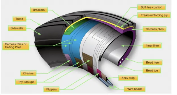
Carcass plies are used to form the tire. They are sometimes called casing plies. An aircraft tyre is constructed for the purpose it serves.
1. They support the weight of an aircraft while it is on the ground.
2. It also provides the necessary traction for braking and stopping of an aeroplane.
3. Tyre also helps to absorb the shock of landing and provide cushioning the roughness of takeoff, roll-out, and taxi operations.
Unlike an automobile or truck tyre, it does not have to carry a load for a long period of continuous operation.
However, an aircraft tyre absorbs the high impact loads of landing, and also it's operating at high speeds for a short time when required.
Bead
The tire bead is an important part of an aircraft tire. It anchors the tire carcass and provides a dimensioned, firm mounting surface for the tire on the wheel rim. Tire beads are strong. They are typically made from high-strength carbon steel wire bundles encased in rubber. One, two, or three bead bundles may be found on each side of the tire depending on its size and the load it is designed to handle. Radial tires have a single bead bundle on each side of the tire. The bead transfers the impact loads and deflection forces to the wheel rim.
Carcass Plies
P r o j e c t -1 :
Powertrain for Aircraft in Runways :
------------------------------------------------------------------------------------------------------------
Part A:
1. Search and list out the total weight of various types of aircrafts.
2. Is there any difference between ground speed and air speed?
3. Why is it not recommended to use aircraft engine power to move it on the ground at Airport?
4. How an aircraft is pushed to runway when its ready to take off?
5. Learn about take off power, tyre design, rolling resistance, tyre pressure, brake forces when landing.
Part B:
6. A. With necessary assumptions, calculate the force and power required to push / pull an aircraft by a towing vehicle.
B. Develop the model for the calculated force and power using Simulink.
7. A. Design an electric powertrain with type of motor, it’s power rating, and energy requirement to fulfill aircraft towing application in Simulink. Estimate the duty cycle range to control the aircraft speed from zero to highest. Make all required assumptions. Prepare a table of assumed parameters. Draw a block diagram of powertrain.
B. Also, Design the parameters in excel sheet.
------------------------------------------------------------------------------------------------------------
|{ PART [A] }|
__________________________________________________________________________________________________________________________________
Aim #1. Search and list out the total weight of various types of aircrafts.
Aircraft
|
Lighter than Air (Aerostat) |
Heavier than Air (Aerodyne) |
|
Any aircraft kept aloft by a gas which are lighter than air falls under this category. |
Aerodyne is the technical name for any type of heavier than air aircraft. This covers all the aircraft that derives flight in principally with the aerodynamic forces. |
Lighter than Air Aerostat)
|
Airship |
Free Balloon |
kite Balloon |
|
These are Aerostats having powerplant propulsions and means of steering the craft. They are made of buoyant by enclosing a volume of gas lighter than air. Here the internal pressure of the gas helps to maintain the shape of the envelope without the need of any longitudinal members. Weight: 1600 kg
|
These are balloons which are not anchored to the ground and are
|
These are balloons which are shaped and trimmed so as to derive stability from wind. |
Heavier than Air (Aerodyne)
|
Engine Driven |
Without Engine |
|||
|
Airplane |
Rotary Wing Aircraft |
Ornithopter |
Glider & Sailplane |
Kite |
|
This is an engine driven aerodyne that achieves lift from the dynamic action of air against fixed wings.
|
This is an engine driven aerodyne that achieves lift from the dynamic action of air
|
This is an engine driven aerodyne that achieves lift from the dynamic action of
|
This is an aerodyne which flies without any applied power due to aerodynamic lift generated by its wings and initial thrust given by some launching mechanism and weighs around 150-200 kgs.
|
|
Airplane
|
Amphibian |
Land plane |
Sea plane |
|
They can take off and land on both land & sea surface. SEASTAR WORLD'S MOST ADVANCED AMPHIBIOUS AIRCRAFT This is the example of Amphibious flight "Sea Star" and weighs around 5150 kg.
|
They can take off and land only on the land surface. Most of the commercial and the military flights come under this. This is the example of commercial flight "Boeing 747" and weighs around 448 ton. 24.5 TONNES 40.00m 5.30 M mal load 9.5 TONNES Fuel (internal) 4.7 TONNES UP TO 67 TONNES 15.30 M• This is the example of defence flight "Rafale" and weighs around 24.5 tonne.
|
They can take off and land only on sea surface. This is the example of Sea plane flight "Cessna 172E" and weighs around 1050 kg.
|
Rotary wing aircraft
|
Gyroplane |
Helicopter |
|
This is a power driven aerodyne which derives lift mainly from a rotor freely rotating in the horizontal plane, but thrust is obtained from a conventio This is the example of Gyroplane "Auto Gyro Calidus" and weighs around 450 kg. nal engine.
|
This is an aerodyne which derives both lift and thrust from rotating rotors. This is the example of Helicopter "Mi 26" and weighs around 22 tons.
|
__________________________________________________________________________________________________________________________________
Aim : 2. Is there any difference between ground speed and air speed?
With reference to the above image, I'm going to differentiate the ground speed and the airspeed. Ground speed is the aircraft speed relative to the ground that it explains how speed can aircraft travel in the ground.
It is not dependent on the airspeed. Here Airspeed is the relative motion between the object and the air. This is also an important parameter for aerodynamic lift generation.
This air speed of the object cannot be measured directly from the ground, it depends upon the ground and the wind speed, in fact it is the "vector difference" between the ground and wind speed.
(As shown in the above figure). On a perfectly still day, the airspeed is equal to the ground speed. But if the wind is blowing in the same direction that the aircraft is moving, the airspeed will be less than the ground speed.
__________________________________________________________________________________________________________________________________
Aim #3 :. Why is it not recommended to use aircraft engine power to move it on the ground at Airport?
"Taxiing" refers to the aircraft movement while on the ground under its own power. This term excludes the accelerating run before takeoff and the decelerating run after landing. The jet engine used is generally not preferred as the primary thrust for taxiing because a large amount of fuel is wasted while the aircraft is still on the ground which could have been used for flying. Since the cost of fuel is one of the biggest expenses in the airline business, many companies are planning to switch to electric taxiing to save fuel and reduce emissions.
There are 2 more important reasons,
i) If the high mounted engines are powered there is a huge risk of the jet blast which may affect the surrounding building and the environment.
li) In case of low mounted engines are turned on there is a higher possibility of any gravel or other impurities lying in the ground may enter the engine and damage it.
Here is where Pushback trucks & Electric taxiing systems use electric motors fitted inside the wheels of the aircraft's landing gear. Electric power is supplied to these motors by an onboard Auxiliary Power Unit (APU). This innovative new approach enables airplanes to move backward and forward solely under electric power. This way, aircraft can avoid reliance on main engines for traversing the airport taxiways while burning fuel unnecessarily.
__________________________________________________________________________________________________________________________________
Aim#4 : . How an aircraft is pushed to runway when its ready to take off?
As explained in the previous answer, "Taxiing" refers to the aircraft movement while on the ground under its own power. This term excludes the accelerating run before take-off and the decelerating run after landing.
So we know the repercussions that might occur when the engine is used on the runway. So Pushback seemed to be a widely popular option for rolling the aircraft on the runway.
Airplanes fly because they are able to generate a force called Lift which normally moves the airplane upward. Lift is generated by the forward motion of the airplane through the air. This motion is produced by the Thrust of the engine(s).
The figure below is a simple diagram of the four forces acting on an airplane – Thrust, Lift , Drag and Weight. Drag is the force produced by the resistance of the air to the forward motion of the airplane. Swish your hand rapidly side-to-side and you will feel that resistance on your hand.
Pushback means the movement of an aircraft from nose-in parking stand using the power of a specialized ground vehicle attached to or supporting the nose landing gear. Conventionally a tow bar is a link used between the aircraft and Pushback tug. Since the pilots have limited vision from the cockpit what lies behind & side of the aircraft, most of the steering will be done by the driver in Pushback.
There are certain factors that is needed to be kept in mind before the aircraft is ready to take-off, it must go through various praparatory pre-takeoff procedures. Among the things that happen to a plane before its boarded and ready to take-off includes:
Restocking the plane with food and necessary items for its next flight.
Cleaning the plane for make it ready for the next flight; this can be quick cleaning job if the plane is doing several flights back to back, or a more thorough one once its itinerary is completed.
Check of onboard systems to see if there is anything that needs to be repaired or monitor.
Refueling
Pushback and getting the plane in position for its next flight.
Preflight checks, boarding and asking for clearence for take-off.
__________________________________________________________________________________________________________________________________
Aim #5: Learn about take off power, tyre design, rolling resistance, tyre pressure, brake forces when landing.
Take-off power: It is the phase where the flight leaves the ground and becomes airborne. Take off performance can be predicted using a simple measure of the acceleration of the aircraft along the runway
based on force equilibrium.
The forces involved will be,
T- Thrust of propulsion system pushing aircraft along runway.
D- Aerodynamic Drag of vehicle resisting the aircraft motion.
F- Rolling resistance friction due to the contact of wheels or skids on the ground.
During take-off run the imbalance in these forces will produce an acceleration along the runway
where dv/dt is the acceleration along the runway and m is the mass of the vehicle.
Rolling resistance:
The friction between aircraft and runway will be proportional to the normal force exerted by the aircraft on the runway.
F=u(W-L)
The normal force will be the difference between Weight of aircraft and and Lift, the friction coefficient will be typically of a magnitude of 0.02 for a standard tarmac runway.
Tyre Design:
When it comes to safety, tyres are one of the most important components of aircraft. They help to absorb the shock of landing and provide cushioning. It also provides the necessary traction for braking and stopping of an aircraft.An aircraft tyre is designed to withstand extremely heavy loads while landing, take off, taxing, and parking. The number of wheels required for aircraft increases with the weight of the aircraft, as the weight of the aeroplane needs to be distributed more evenly.
Carcass plies are used to form the tire. They are sometimes called casing plies. An aircraft tyre is constructed for the purpose it serves.
1. They support the weight of an aircraft while it is on the ground.
Carcass plies, or casing plies as they are sometimes called, are used to form the tire. Each ply consists of fabric, usually nylon, sandwiched between two layers of rubber. The plies are applied in layers to give the
tire strength and form the carcass body of the tire. The ends of each ply are anchored by wrapping them around the bead on both sides of the tire to form the ply turn-ups. As mentioned, the angle of the fiber in
the ply is manipulated to create a bias tire or radial tire as desired.
Tread
The tread is the crown area of the tire designed to come in contact with the ground. It is a rubber compound formulated to resist wear, abrasion, cutting, and cracking. It also is made to resist heat build- up. Most modern aircraft tire tread is formed with circumferential grooves that create tire ribs. The grooves provide cooling and help channel water from under the tire in wet conditions to increase adhesion to the ground surface.
Sidewall
The sidewall of an aircraft tire is a layer of rubber designed to protect the carcass plies. It may contain compounds designed to resist the negative effects of ozone on the tire. It also is the area where information about the tire is contained. The tire sidewall imparts little strength to the cord body. Its main function is protection.
Tire Pressure: The pressure usually operates at higher pressure up to 200 psi for domestic and as well international flights which are usually heavier.
Brake forces when landing-
There are three kinds of braking forces that can be employed in the aircraft to decelerate it in the run way.
1. Engine power: The most important action to achieve deceleration from a speed at which the engines are still producing forward motion is to select all thrust/ power levers to the ground idle position promptly, and if available, continue the action through to the selection of reverse thrust or reverse propeller pitch. Thrust reversers and reverse propeller pitch are most effective at high speeds.
2. Wheel brakes: To be effective, braking action at any speed depends upon sufficient friction existing between the tires and the runway surface achieved through freely rotating wheels.
3. Mechanical spoilers: The mechanical deflection of parts of the wing upper surfaces and tail cone assembly can assist deceleration in two ways:
1 . Directly, by increasing derodynamic drag on the moving aircraft. This can be achieved by raising upper wing surface panels called ground spoilers or by operation of a tail cone 'clamshell' type air brake.
2 . Indirectly by increasing the effective downward load on the landing gear and thereby increasing the efficiency of wheel braking.
__________________________________________________________________________________________________________________________________
PART -B
__________________________________________________________________________________________________________________________________
Aim : #6 A. With necessary assumptions, calculate the force and power required to push / pull an aircraft by a towing vehicle.
The forces required to push/ pull an aircraft by a towing vehicle are given as follows:
• Rolling Resistance Force: As discussed earlier, it is the force which is responsible for resisting the motion of the
body such as ball, tire or wheel, when its starts to roll on the surface. The governing equation of this force is
given by:
F= C *m*g.
where, C- Rolling Resistance Co-efficient (dimensionless)
m- mass of the body under consideration
g- acceleration due to gravity.
Aerodynamic Drag Force; Drag is the aerodynamic force which opposes the motion of the body. It is actually the resistance offered by the air to the movement of the body. So when a car is moving it is actually displaces
the air which in turn affects the car's speed and its performance. Manufacturers always try to keep the Aerodynamic Drag to the minimum possible value. It is due to the fact that this force has a negative impact on the vehicle's performance and the efficiency. The upright stance of some vehicles gives it a drag co-efficient of 1.30 while a randrop design has the least amount of drag. The governing equation of these force is given as follows:
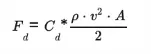
where,
A - It is the reference area (frontal area of the car)
v- It is the velocity/flow velocity relative to the object (speed of the car)
ρ- Air Density
C- It is the Drag Coefficient which is dimensionless related to the object's geometry and take into account both skin friction and form drag.
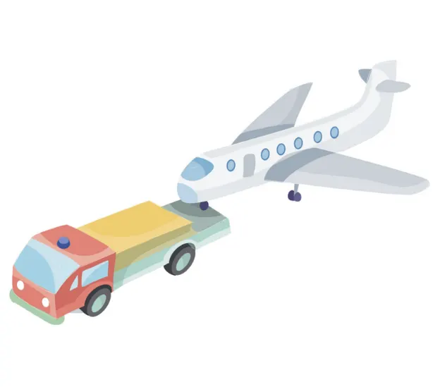
Lets take an example on our assumption ...
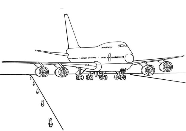
-----------------------------------------------------------------------------------------------
Taking the values of Aircraft 380, the specifications are,
Mass = 198000kg
Height = 16.80m
Width = 48.90m
Frontal area A = Height x Width = 16.80x48.90 = 821.52m^2
Drag coefficient Cd = 0.032
Air density p = 1.23kg/m*
-----------------------------------------------------------------------------------------------
Taking the values of towing vehicle TBL480,
Mass = 47000kg
Height = 2.6m
Width = 3.9m
Frontal area A = Height × Width = 2.6 X 3.9 = 10.4m^2
Tyre size R = 28" = 0.7111m
Drag coefficient Cd = 0.6
Air density p = 1.225kg/m^2
Coefficient of rolling resistance ur = 0.028
Speed v = 32kmph = 32x5/18 = 8.89m/s.
-----------------------------------------------------------------------------------------------
Now calculating the forces which are acting in the push or pull of an aircraft by a towing vehicle,
Forces are,
Rolling resistance force = Frr
Airdrag force = Fad
Formulas using:
Frr = urr × m × g
Where m = mass of the body
ur = Coefficient of rolling resistance
g = Gravitation = 9.8 m^2
Fad =1/2x pxAxCdxv^2
p = Air density
A = Frontal area
Cd = Drag coefficient
V = Speed.
Now the calculations are,
-----------------------------------------------------------------------------------------------
rolling resistance force calculations
Rolling resistance force of an aircraft Frrl = ur x m × g
Frr1 = 0.028 x 198000 x 9.8
Frr1 = 54331N
Rolling resistance force of a Towing vehicle Frr2 = ur x m × g
Frr2 = 0.028 x 47000 x 9.8
Frr2 = 12896N
Total Rolling resistance force Frr = Frr1 + Frr2
Frr = 54331 + 12896
Frr = 67227N
------------------------------------------------------------------------------------
airdrag force calculation:
Air drag force of an aircraft Fad = 1/2 x p × A x Cd x v^2
Fad1 = 1/2 x 1.23 x 821 x 0.032 x 8.89^2
Fad1 = 1277N
Air drag force of a towing vehicle Fad2 = 1/2 x p * A * Cd x V^2
Fad2 = 1/2 x 1.225 x 10.4 x 0.6 x 8.892^2
Fad2 = 302N
Total Airdrag force Fad = Fad1 + Fad2
Fad = 1277 N + 302N
Fad = 1579N
------------------------------------------------------------------------------------
Total Forces acting Ft = Frr + Fad
Ft = 67,228 + 1579
Ft = 68,807N
Here we are neglected Hill climbing force and acceleration force.
Total Power Pt = Ft x V
Pt = 68,806 x 8.89
Pt = 6,11,685W
Pt = 611.685KW.
Now we calculate the below values,
Total force required to push / pull an aircraft by a towing vehicle = 68806N.
Total power required to push / pull an aircraft by a towing vehicle = 611.68Kw.
__________________________________________________________________________________________________________________________________
B. Develop the model for the calculated force and power using Simulink.
Now we have to create a simulink model for the above calculated force and power, In a simulink model first i have created sunsystems for both Rolling resistance force and Airdrag force, and connected them to a addition block to calculate the Total force. And take a connection from the output of addition block connected it to the product block and speed is also connected to product block. From the output of product block we calculated the power.
Calculations are taken according to the formulas. And display blocks are taken to display the values.
The following figure shows the simulink model to calculate force and power.
Final model :
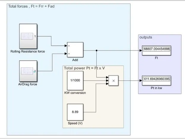
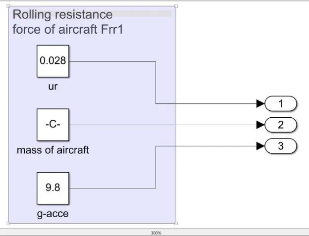
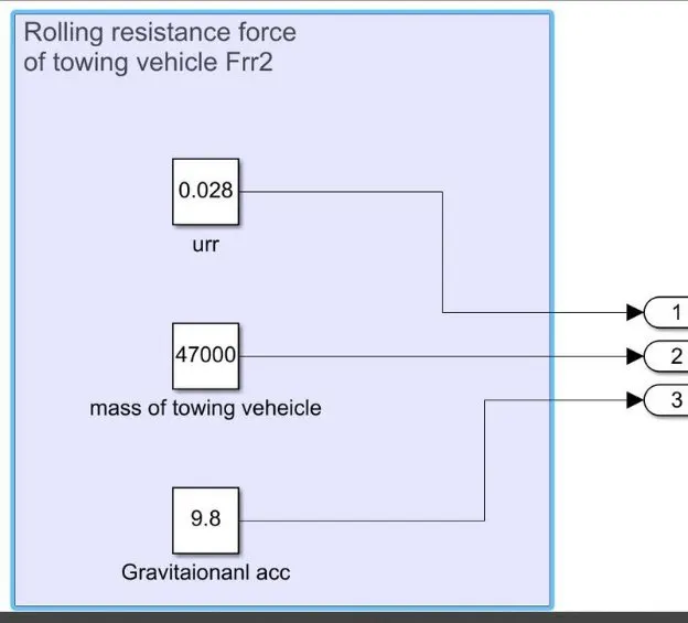
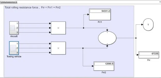
So now from the above Simulink model, by opening the subsystem of rolling resistance force we can see the following connections. Where the rolling resistance force is calculated for both aircraft and towing vehicle and given their outputs to the addition block to calculatate the total Rolling resistance force. And taken a display block to show the value. And taken a output port of subsystem across the output of addition block.
1 : Rolling resistance force of aircarft Frr1
2 : Rolling resistance force of Towing car Frr2
3 : Total Rolling resistance force [ Both aircarft & towing vehicle ] Frr = Frr1 + Frr2
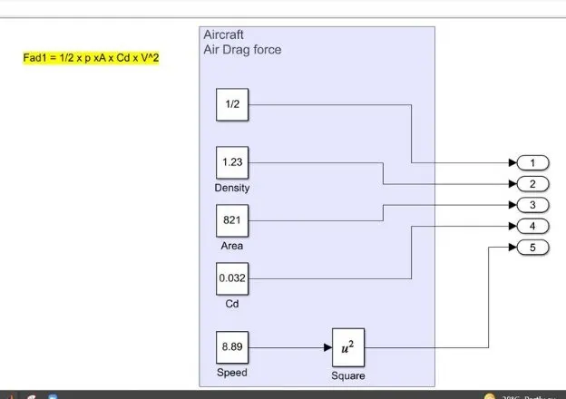
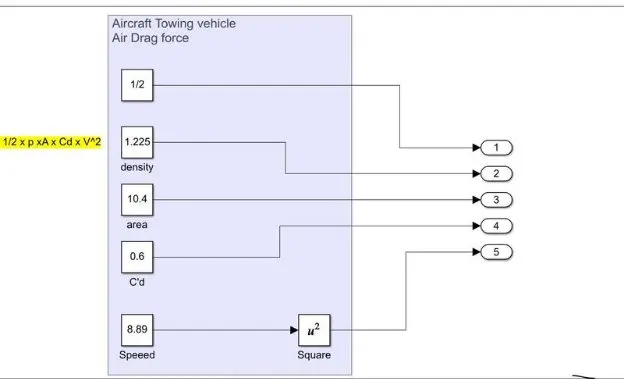
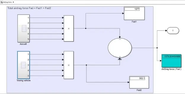
Now we have opened the subsystem block of Airdrag force. Where the following connections will displayed. The upper part of the model is to calculate the airdrag force of aircraft and lower part of the model is to calculate the airdrag force of a towing vehicle. The both outputs from the aircraft ang towing vehicle is given to addition block to calculate the total airdrag force. Display block displays the total airdrag force.
4 : AirDrag force of Aircraft Fad1
5 : AirDrag force of Towing vehicle Fad2
6 : AirDrag force of [ both Aircraft & towing vehicle ] Fad = Fad1 + Fad2
__________________________________________________________________________________________________________________________________
Aim #7 :
A. Design an electric powertrain with type of motor, it’s power rating, and energy requirement to fulfill aircraft towing application in Simulink. Estimate the duty cycle range to control the aircraft speed from zero to highest. Make all required assumptions. Prepare a table of assumed parameters. Draw a block diagram of powertrain.
Energy required:
Energy = Power × Time
From the above question the power calculated is,
Power P = 611.685 KW
Time is assumed as 20 minutes which is converter to hours as 0.33h
Time t = 0.33h
now,
Energy = 611.685 x 0.33
Energy = 201.85 KWh
The energy required for the above calculated power for 20 minutes is 201.85 KWh.
Now we have to calculate the input power to drive the duty cycle of the towing vehicle. The output power is taken
from the above question, those values are considered based on certain assumptions and calculations from the towing vehicle TBL480.
Duty cycle = Power output/Power input
Where the power input is to be calculated based upon the assumptions of the Motor specifications,
Input voltage = 650V
Input current = 600A
Now, Power input = Input voltage × Input current
Power input = 650 × 600
Power input = 390000W
Power input = 390KW
From the calculated values, duty cycle is,
Duty cycle = Power output/Power input
Duty cycle = 356.41/390
Duty Cycle = 0.91
% Duty cycle = 91%
|
PARAMETER |
PARAMETER |
|
Aircraft |
|
|
Mass |
198000kg |
|
Height |
16m 48s |
|
Width |
48m 54s |
|
Air density |
1.23kg/m^3 |
|
Drag coefficient |
0.0265 |
|
Towing vehicle |
|
|
Mass |
47000kg |
|
Height |
2.0m |
|
Width |
3.4m |
|
Tyre size |
0.5588m |
|
Drag coefficient |
0.6 |
|
Air density |
1.225kg/m^3 |
|
Speed |
8.89m/s |
|
Coefficient of rolling resistance |
0.02 |
The duty cycle required for towing the vehicle TBL280 is 91%
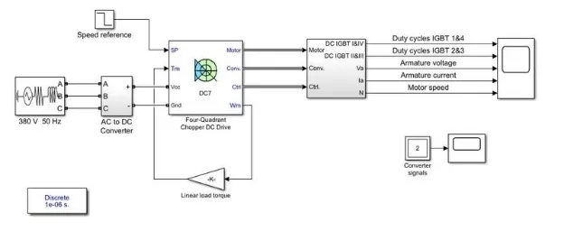
Simulink block diagram :
AC to DC converter
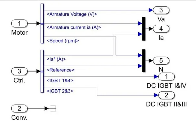
signal selector bus :
GRAPH:
output results .
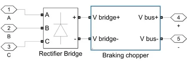
Here AC to DC converter is used because we have taken the input as AC so to convert into Dc we are using the converter.
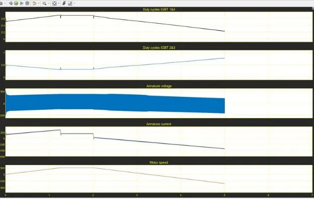
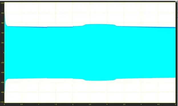
In the above simulink model we have taken a supply of 380V as voltage. AC to DC converter is used to convert the given supply into DC. Because we are using a DC drive as it requires Dc supply only. The converter output gives values to the DC7 block which gives the values to selector block. From the selector block the value of voltage, current, speed and duty cycles are given to the scope block. The scope block gives the resultant plots.
__________________________________________________________________________________________________________________________________
Aim #8 B. Also, Design the parameters in excel sheet.
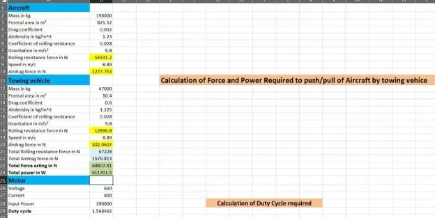
Here we are designig an excel sheet with the parameters assumed, and calculated the required values. The following image shows the excel calculation using the parameters.