Project-1: Powertrain for aircraft in runways
Question 1:
Aim: To explain the Total weights of Different Aircrafts
Total weights of Different Types of Aircrafts
Thw toatal weight or Maximum Gross Takeoff Weight includes mainly three factors
- Passengers
- Fuel
- Cargo
the aircraft weight itself called kerb Weight or Empty Weight it also considered for calculating Total Takeoff Weight
Lets see the Total weight of different aircrafts
| Aircraft | Empty Weight | Max Fuel Weight | Max Cargo Weight | Max Gross Takeoff weight |
| Antanov AN-225 | 285000kg | 300000kg | 190000kg | 640000kg |
| Airbus A380-800 | 277000kg | 254000kg | 84000kg | 575000kg |
| Boeing 747-800 | 220100kg | 194000kg | 134000kg | 447700kg |
| Airbus A340-500 | 168000kg | 175000kg | 54000kg | 372000kg |
| Boeing 777-300ER | 168000kg | 145500kg | 67100kg | 352000kg |
| Boeing 787-10 | 135500kg | 101500kg | 57300kg | 254000kg |
| Boeing 737-900 | 44700kg | 24000kg | 20200kg | 85000kg |
| Airbus A320-100 | 42600kg | 22100kg | 20000kg | 68000kg |
| Embraer190 | 28800kg | 13000kg | 13100kg | 48000kg |
| Gulfstream G650 | 24500kg | 21900kg | 3000kg | 45200kg |
| Bombardier CRJ900 | 21850kg | 8900kg | 2760kg | 36500kg |
| Bombardier O400 | 17800kg | 5300kg | 8500kg | 28000kg |
| Learjet 75 | 6300kg | 2750kg | 1300kg | 9700kg |
| Cessna Citation CJ4 | 4700kg | 2650kg | 1000kg | 7800kg |
| Beechcraft King Air B100 | 3200kg | 1450kg | 1900kg | 5400kg |
| Diamond DA50 RG | 1450kg | 155kg | 560kg | 2000kg |
| Beechcraft Bonanza G36 | 1150kg | 200kg | 385kg | 1660kg |
| Cessna 206H | 990kg | 235kg | 520kg | 1630kg |
| Sirrus SR22 | 1000kg | 220kg | 430kg | 1630kg |
| Cessna 172R | 770kg | 170kg | 255kg | 1100kg |
the above table indicates Total Weight for different Aircrafts we can observe that the minimum Total Gross Weight of the plane should be 1Tonn
The Cargo Weight means the weight of cargo passengers crew food etc.,
Question 2:
Aim: To Explain the Difference between the Ground speed and the Air speed
Groundspeed is the speed of the aircraft directly over the ground. It is a vector quantity. Higher the ground speed the faster you reach your destination. Airspeed is the speed of the aircraft relative to the speed of surrounding air in which the aircraft is flying.
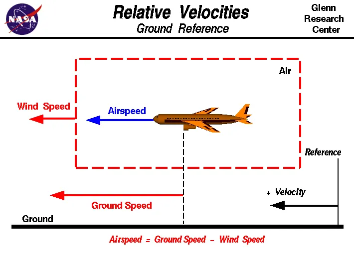
Actually, there are many types of airspeed. They are namely
- Indicated Airspeed,
- Calibrated Airspeed,
- True airspeed and,
- equivalent airspeed.
True airspeed is the speed of the aircraft relative to the airmass in which it is flying. It is the airspeed of the aircraft used for exact navigation.
If the airspeed is positive, that is, moving in the direction of aircraft, the aircraft will have a higher groundspeed. This is known as Tailwind.
On the other hand, if it is moving opposite to the direction of aircraft, that is negative wind, it will decrease the aircraft's groundspeed. This is known as Headwind.
Thus,
Groundspeed= Airspeed + Windspeed.
For example, if an aircraft is moving at airspeed of 500 mph and there is a tailwind of 265 mph, then ground speed of the aircraft will be 765 mph.
Again, if it is 265 mph headwind, then groundspeed would be only 235 mph.
During takeoff, the ground speed of the aircraft is not important. It is the airspeed which is important. During takeoff, airspeed will be the speed of the air flowing over the wings to generate lift.
if an aircraft can takeoff at 200 mph airspeed and there is a headwind of 50 mph, then it will have to attain a groundspeed of 200–50= 150 mph, to get a airspeed of 200 mph. Thus plane can use a shorter length of runway to takeoff. If there it would be tailwind, the plane will have to use a longer length of runway to takeoff.
If the air is moving in the direction of aircraft, wind is considered to be Positive and if air moving against the aircraft, it is considered to be Negative.
Question 3:
Aim: To Why is it not recommended to use aircraft engine power to move it on the ground at Airport.
Aircraft towing equipment is typically used for the towing and pushback process to avoid some of the significant hazards posed by aircraft engines. When an aircraft's engine is activated, the thrust can create a high-speed wind that can easily cause damage to the airport terminal, surrounding ground vehicles, jetway, baggage and most importantly, ground personnel.
Suppressing the use of engines is especially important when towing a large aircraft, as their more powerful thrust capabilities can become exceedingly dangerous. Engine thrust can easily send any loose items airborne, turn the tiniest grains of dust into hazardous projectiles and create debris that can cause damage to multi-million dollar engines. Additionally, aircraft engines consume a great deal of fuel and generate extreme noise that can be harmful to ground personnel. Using a pushback tug for aircraft is simply a more economical and safer option than running the engines.
the power hazaerd areas are shown in below diagram
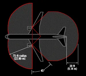
the power hazard area where aircraft thrust makes million dollor equipment damage
Typically, most aircraft cannot move in reverse without the help of aircraft towing equipment. Planes are not designed with a reverse option that pilots can use for backward movement, so pushback tugs for aircraft are the only option when moving aircraft to hanger or away from the terminal building. This is because aircraft are not outfitted with gears or transmission for propulsion – power for movement is derived solely from the engines through thrust. When aircraft tugs are used to tow planes, an airline can maximize safety and optimize efficiency with on-ground operations.
While most commercial airliners with jet engines have thrust-reversing capabilities, they can only be used as additional braking power during landing. In addition to the problems mentioned above associated with using aircraft engines, reverse thrust also has what is known as the lowest-speed-of-operation limit. If reverse thrust is used below the speed of 80kts, it's very likely the engines will become heavily damaged.
Question 4:
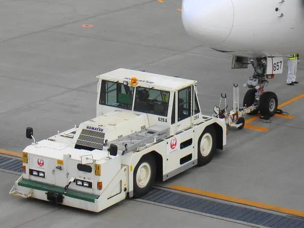
Aim: How an aircraft is pushed to runway when its ready to take off.
Question 5:
Aim: Learn about take off power, tyre design, rolling resistance, tyre pressure, brake forces when landing.
Take of power required to keep the aircraft in the air without fail:
-
The take off power required mainly depends upon the kinetic energy of the vehicle and the height i.e, potential energy of the aircraft.
- The total energy of an aircraft flying in the atmosphere can be calculated from the below energy equation:
E = ½ m v2 + mgh
here m = total mass of the aircraft
v = velocity with which air craft is moving.
g = acceleration due to gravity
h = height at which aircraft is moving
- A Boeing 737-300 has a maximum takeoff weight of 5.65 × 10⁴ kg, a cruise altitude of h = 10,195 m, and cruise speed of 221 m/sec. Inserting these numbers into the above equation, we obtain 7.03 GJ for the energy at cruise conditions. [3] However, the engines mounted onto the wings of the plane are required to provide additional energy per time, power, in order to keep the aircraft flying at a constant altitude and speed.
- The extra power needed to overcome the drag acting on the airplane can be given by the following equation :
P = (dh/dt) m g
Here dh/dt = the decent speed required to keep the plane's speed constant if the engines fail.
m = mass of the aircraft
g = acceleration due to gravity
Tyre Design :
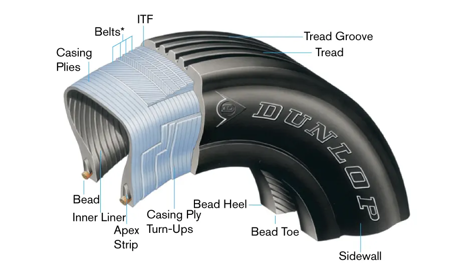
Aircraft tires can easily be taken for granted. Their simplistic appearance may lead some to a false feeling of complacency. Many technicians are not aware of the critical design factors that go into every aircraft tire in use today. Seemingly minor flaws can lead to disastrous results, and inadequate maintenance practices can cause shortened tire life and even cause unsafe operating conditions.
When one considers the forces that aircraft tires endure, it seems amazing that engineers were ever able to develop these special products. Some tires are subjected to speeds as fast as a race car while at the same time supporting more weight than the largest land moving machines. They go through cyclic exposure to varying temperatures and pressures. These factors make aircraft tire design a critical process and tire maintenance an ever important step in safe aircraft operation.
Designing aircraft tires is a very intense undertaking. Once an aircraft manufacturer goes to the tire manufacturer with the size and weight requirements, the tire manufacturer begins the process of designing a tire that meets the needs of the aircraft manufacturer as well as all regulatory requirements — including foreign regulations in many cases.
Engineers are challenged with designing tires with cool running, heat-resistant materials while simultaneously exceeding tire service requirements. Tire prototypes are put through rigorous tests that simulate cycles of landings, take-offs, and taxi operations. It is only after the tires pass all mandatory tests and meet the requirements of the aircraft manufacturer and airworthiness authorities that the tires are put into production.
Two types of tires are used in aircraft applications — bias-ply tires and radial tires. Although both types of tires share some similarities in design, there are differences that need to be noted.
Bias-ply tire construction :
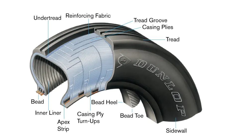
Radial-ply tire construction :
ROLLING RESISTANCE IN AIRCRAFT :
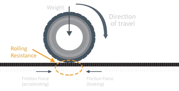
Rolling resistance, sometimes called rolling friction or rolling drag, is the force resisting the motion when a body (such as a ball, tire, or wheel) rolls on a surface. It is mainly caused by non-elastic effects; that is, not all the energy needed for deformation (or movement) of the wheel, roadbed, etc., is recovered when the pressure is removed. Two forms of this are hysterises losses and permanent (plastic) deformation of the object or the surface (e.g. soil). Another cause of rolling resistance lies in the slippage between the wheel and the surface, which dissipates energy.
The rolling resistance force will be given by the equation as :
F = μ*mg
here :
μ = rolling resistance coefficient
m = total mass of aircraft
g = acceleration due to gravity
But when we consider the extreme condition the surace when considered with a snow we take many considerations into account :
When taking off from a runway covered with slush, standing water or snow, the required take-off ground-run distance will be longer than on a dry runway. This is the result of the fact thatslush, standing water and snow on the runway will generate a rolling resistance that increasesthe total resistance on the aircraft during the ground-run.
Snow is a porous, permeable aggregate of ice grains, which can be single crystals, or closegroupings of several crystals. Air and water vapor surround the crystals. Snow is a complicatedmaterial because of the variety of forms it can take and because it is thermodynamicallyunstable, which means that the physical properties of the snow can change with time (known assnow metamorphism). A large number of different types of snow are known. A possibleclassification of these types including typical densities, is given as follows:
•New snow (50-200 kg/m3)
•Powder snow (200-450 kg/m3)
•Compacted snow (450-700 kg/m3)
•Wet snow (300-700 kg/m3)
All these types of snow are compressible. This means that the volume changes when the snow isloaded. This volume change becomes evident as surface compaction. Density is probably themost useful single parameter of snow properties because e.g. structural characteristics showsome correlation with density. The compression strength of snow, and thus its bearing capacity,also appears to be strongly influenced by its density. Below a density of 400 kg/m3 the bearingcapacity of snow is usually very low resulting in large volume changes of the snow when it isloaded. At higher densities higher loads are required to compress the snow. Whenever snow issubjected to loads e.g. by moving the snow with a bulldozer or running a tire over it, the snowbecomes stronger than natural snow of the same density. This is a result of bond growthbetween the ice crystals. As already pointed out, snow is metamorphic. Environmentalinfluences like wind, temperature fluctuations, and rain can change the characteristics of snowwithin days and even within hours.
The total rolling resistance of an aircraft rolling along a snow-covered runway is given by:
Drolling = Dr+Dc+Dd
In which Dr is the rolling resistance on a dry hard surface. The equations presented in this paperfor Dc and Dd are for single tires. A complete aircraft has at least 3 tires, one on each mainlanding gear and one on the nose landing gear. To obtain the total aircraft rolling resistance dueto snow, the resistance Dc and Dd for each single tire have to be calculated and summed.
TYRE PRESSURE :
An aircraft tire or tyre is designed to withstand extremely heavy loads for short durations. The number of tires required for aircraft increases with the weight of the aircraft, as the weight of the airplane needs to be distributed more evenly. Aircraft tire tread patterns are designed to facilitate stability in high crosswood conditions, to channel water away to prevent hydroplaning, and for braking effect.
Aircraft tires also include fusible plugs (which are assembled on the inside of the wheels), designed to melt at a certain temperature. Tires often overheat if maximum braking is applied during an aborted takeoff or an emergency landing. The fuses provide a safer failure mode that prevents tire explosions by deflating in a controlled manner, thus minimizing damage to aircraft and objects in the surrounding environment.
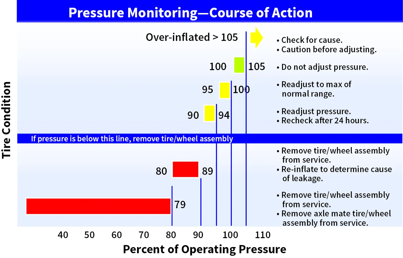
The below image shows the comparision between the car and aircraft tyre pressure comparision :
| CAR TYRE | AIRCRAFT (1) | AIR CRAFT (2) | |
| Typical | (737 NLG) | (737 NLG) | (F-16 Blk 40 MLG) |
| Size | P205/75 R15 | 27x7.75 R15 | 27.75x8.75R14.5 |
| Outside Diameter | 27.2 inch | 27 inch | 27.75 inch |
| Selection Width | 8.1 inch | 7.75 inch | 8.75 inch |
| Max Inflation | 35 psi | 200 psi | 320psi |
| Max Load | 1,598 lbs | 9,650 lbs | 21,500 lbs. |
| Speed Rating | 106 mph | 225 mph | 259 mph |
| Operation | Continuous | Intermittent | Intermittent |
| Temperature | Equilibrium | No Equilibrium | No Equilibrium |
By the above variation we can assume that what will be the pressure of aircrafts with respect to the normal 4 wheeler vehicles.
BRAKES FORCES WHILE LANDING :
Early aircraft had a single braking system with no backup or redundancy. This was seen as impractical by the operators and unacceptable by the regulating authorities so manufacturers were soon incorporating more robust braking systems into their designs. Some of the earlier solutions simply addressed the loss of the primary hydraulic pump and incorporated hand pumps or electrically driven hydraulic pumps to provide an alternate source of hydraulic pressure. These solutions did not address failures due to loss of fluid and were deemed inadequate. To overcome this, some manufacturers such as Convair incorporated a compressed air system into their designs for emergency braking. While it achieved the requirement of providing an independent means of activating the brakes, it was limited in that it did not allow for differential braking and in that the tank contained a finite amount of compressed air. Braking redundancy in most large passenger aircraft today is achieved by multiple, independent hydraulic systems backed up by accumulators. These systems allow for several layers of failure without resulting in total loss of braking capability.
Break System Enhancements
Anti-skid, auto-brake, brake temperature indicators and brake fans are all systems which enhance the performance of the aircraft brakes.
Anti skid Breaking System:
The anti-skid system, through various mechanisms, compares the speed of the aircraft with the rotational speed of each main wheel. If the speed of any wheel is too slow for the existing aircraft speed, the brake on that wheel (or wheels) is released momentarily to allow the wheel speed to increase and prevent the wheel from skidding. The system is fully automatic and is active from immediately after initial wheel spin up on landing (during which time brake activation might (or might not) be inhibited) down to a design limited minimum speed; usually about 15 knots. Anti-skid systems are designed to minimise aquaplanning and the potential tyre damage which can occur when a wheel is locked or rotating at a speed which does not correspond to the speed of the aircraft. Anti-skid removes the possibility of reverted rubber skids caused by locked wheels. An anti-skid system also greatly improves stopping distance on substandard surfaces such as gravel or grass and is particularly effective on surfaces contaminated with frozen contaminants such as ice or slush by ensuring maximum effective breaking.
Auto Brake System:
Auto-brake systems can be used on takeoff where they will provide maximum braking in the event of a rejected take-off and on landing where they will provide a scheduled rate of deceleration (dependent upon the auto-brake level selected) using only a single brake application. These features combine to optimize the brake usage with respect to the requirement and to minimize brake wear.
Question 6:
Aim: To calculate the force and power required to push / pull an aircraft by a towing vehicle With necessary assumptions.
the towing vehicles are used to pushback the aircrafts to the runways or to hangers
as the airport has a plain concrete surface the vehicle is acted by only rolling resistance force and air drag force
although the minimal number of forces the aircraft weighs a massive ammount of weight the towing vehicle needs to generate high amount of power
when coming to the acceleration the towing vehicle does not need tro accelerate as the aircraft may sturdle so we are not considering the acceleration force
Rolling rasistance force `F_(rr)`:
`F_(rr)=mu_(rr)xxmxxg`
where `mu_(rr)`is rolling resistance constant
m is Total Gross weight of the vehicle
g is the coefficient of gravity
Total gross weight = weight of the Towing vehicle + Take off weight of the aircraf
`F_(rr)=0.02xx(35000+164000)xx9.81`
Air drag Force `F_(ad)`
`F_(ad)=1/2rhoAC_dv^2`
`rho` = 1.225 kg/m^3
A( frontal area)= hieght of tghe aircraft*width of the aircraft
A=15.80*43.90=693.62 m^2
`C_d`air drag coeficient 0.0265
the towing vehicles does not need to rush as the nose gear of the aircraft may damage
so, assuming that the towing vehicle moves at the speed of 20kmph
V = (20*5/18)=5.56m/s
`F_(ad)=1/2xx1.225xx693.62xx0.0265xx(5.56)^2`
now the total forces acting on the towing vehicle
`F_T = F_(rr)+F_(ad)`
the total power required by the towing vehicle is
`P_T=F_Txxv`
now lets make a model in SIMULINK to calculate the above forces
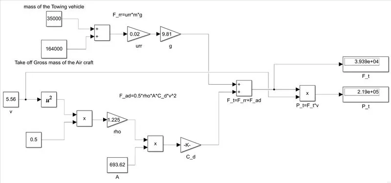
we can observe the total forces acting on a towing vehicle
as well as
total power required to overcome these forces in the displays
Question 7:
Aim: Design an electric powertrain with type of motor, it’s power rating, and energy requirement to fulfill aircraft towing application in Simulink. Estimate the duty cycle range to control the aircraft speed from zero to highest. Make all required assumptions. Prepare a table of assumed parameters. Draw a block diagram of powertrain.
let us consider a towing vehicle as indicated as above
with
`F_T =39390N`
`P_T=219000W`
let us assume that the towing vehicle tows for 20 min which is equal to 0.35H
then the energy consuming is
`E_t=P_Txxt`
`=>E_t=219xx0.35
`=>E_t=76.65kwh`
consider radius of the wheel to be 0.813m
calculating the motor torque as`tau =(F_Txxr)/(Gxxeta_g`
considering the gear efficiency 95%
then`eta_g=0.95`
the common gear ratio to achieve such big loads is 27
then the `tau = (39390xx0.813)/(27xx0.95)`=1248.6Nm
the speed of the motor is calculated as `omega=P_T/tau`=219000/1248.6=175.39rad/sec
the motor required for the towing application is an stalled motor so that it has to exhibit high amount of torque throught the operation
basically this motor is designed for low speed and high torque application
let us simulate the DC Drive with load torque as calculated above
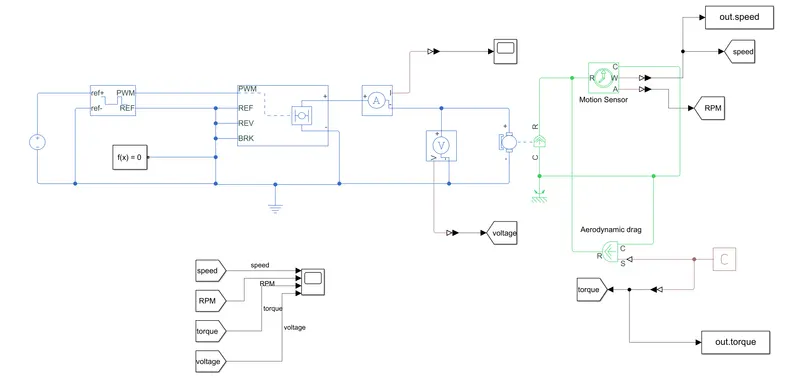
| DC Voltage Source | 48v |
| controlled Pwm generator | 48v,1000Hz |
| H-bridge | 48v,440v |
| BLDC | 440v, 1300N*m, 200RPM |
| Load Torque as calculated | 1248.6 N*m |
above mentioned are the considered values let us see the output results
Results:
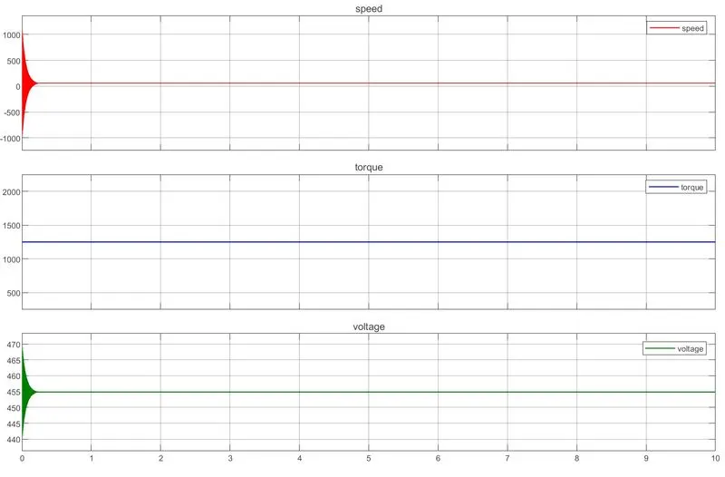
By observing the above results the required torque is achieved by the considered motor
we can observe high current and voltage due to stalled condition the starting torque requires high currents
the torque is maintained same throught the simulation which is the major consideration for stalled motors used for towing application
Duty cycle of the Aircraft to reach zero to highest speed:
Consider the Airplane that can lift off at 200kmph
the airspeed and wind speed is considered randomly to calculate groundspeed
`"Groundspeed"="Airspeed"-"Windspeed"`
let us create a excel spread sheet to calculate and plot the aircraft liftoff or takeoff speed
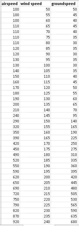
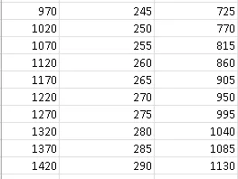
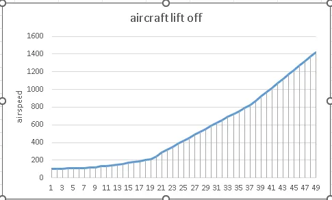
we can observe that the lift off is taken at groundspeed 200kmph from the plot
comercial vehicles can go maximum speeds upto 550kmph
by observing the above plot we can say that
the duty cycle of the range of aircraft speed from zero to highest is calculated as
the range of zero to highest speed of the aircraft is achieved with the thrusters which are engines
but let us assume that both the engines are replaced by electric motors and fuel tank with battery pack
lets calculate the required motor parameters
`N=v/(0.1885xxD_m)`
N is speed of the motor in rpm
D_m is diameter of the propeller in meters
Torque of the Motor is calculated as
`tau_m= (F_Txxr)/(Gxxeta_g)`
where `tau_m`torque of the motor
`F_T`is Total forces acting on aircraft
`G`is gear ratio
`eta_g`efficiency of gears
Total required power of the Motor
`P_m=(tau_mxxN_m)/9.5488`
lets assume that the aircraft is travelling from one place to another place in one hour
then the energy required by the aircraft is
`E=P_mxxt`
t is time travelled
E is energy required by the motor which is come under battery capacity
lets assume auxilary loads and there are two motors employed on both sides so
it has to supply for both motors
`E=(P_m1+P_m2+P_a)xxt`
where E is energy required by the aircraft or required battery capacity
Pm1 is left wing motor power
pm2 is right wing motor power
pa is power required for auxilary loads
Now, the Duty cycle of the Power electronic converter for the range of aircraft speed from zero to highest is calculated as follows
`D= P_("out")/P_("in")`
`P_("in")`is battery power supplied
`P_("out")`is the output power delivered to both motors and other auxilary loads of the aircrafts
Thus the Duty cycle of the range of aircraft speed from zero to highest is calculated
Table for assumed parameters:
| mass of the aircraft | 164000 |
| mass of the Towing vehicle | 35000 |
| Total Gross Weight | 199000 |
| Rolling resistace constant | 0.02 |
| gravitational coeficient | 9.81 |
| Rolling resistace Force Frr | 39043.8 |
| Air density ρ | 1.225 |
| Frontal area | 693.62 |
| Air drag Coefficient Cd | 0.0265 |
| velocity of the vehicle | 5.56 |
| Airdrag Force Fad | 348.0351896 |
| Total Forces acting on a Towing vehicle FT | 39391.83519 |
| Total Power required by the Towing vehicle to overcome the acting Forces on it PT in kW | 219.0186037 |
| Total time required to pushback aircraft t in hrs | 0.35 |
| Energy Required By the Towing Vehicle to pushback aircraft in kWh | 76.65651128 |
| gear ratio considered G | 27 |
| Gear efficiency ɳg | 0.95 |
| Radius of the Towing vehcle wheel in m | 0.813 |
| Torque Required by the Motor τm | 1248.559922 |
| Angular velocity of the motor Ѡm in rad/sec | 175.4169742 |
| Energy required by the Motor or Battery Capacity in kWh | 76.65651128 |
| Battery Power Required | 219.0186037 |
| Duty Cycle of the Power electronic converter of an Towing Vehicle in % | 100 |
BlockDiagram of PowerTrain of an Towing Vehicle:
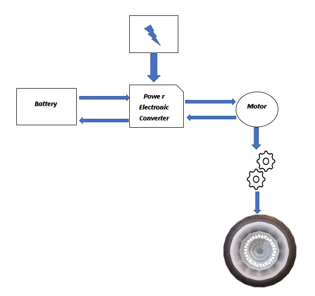
we can observe the block diagram of power train for Towing Vehicle
the power comes from the charging station taken to the power electronic converter and fed to the battery
after charging the battery feds to the power electriniv converter which acts as an dc-dc converter and feds to motor
the motor with gear ratio powers the wheel with required torque
The Parameters required by an Towing vehicle to pushback an aircraft is calculated in excell sheet also and attached
Towing_vehicle_parameters_calculater
Conclusion:
- The total weight of various types of aircrafts are listed.
- The difference between ground speed and air speed explained.
- Why is it not recommended to use aircraft engine power to move it on the ground at Airport is explained.
- How an aircraft is pushed to runway when its ready to take off is explained
- Take off power, tyre design, rolling resistance, tyre pressure, brake forces when landing of an Aircraft is explained.
- The force and power required to push / pull an aircraft by a towing vehicle is derived.
- The model for the calculated force and power using Simulink is developed.
- An electric powertrain with type of motor, it’s power rating, and energy requirement to fulfill aircraft towing application in Simulink.
- The duty cycle range to control the aircraft speed from zero to highest is estimated using excel sheet.
- A table of assumed parameters is prepared.
- A block diagram of powertrain Drawn.