Project-1: Powertrain for aircraft in runways
Part A:
1. Search and list out the total weight of various types of aircrafts.
ANS:
An aircraft is a vehicle or machine that is able to fly by gaining support from the air. It counters the force of gravity by using either static lift or by using the dynamic lift of an airfoil, or in a few cases the downward thrust from jet engines.
An aircraft is any machine that can fly. Airplanes, hot air balloons, helicopters, or even flying platforms are considered aircraft An airplane is a specific type of aircraft that has fixed wings and is heavier than air that is capable of sustained, powered, and controlled flight.
- Airplane – Single-engine land or sea or multi-engine land or sea.
- Rotorcraft – helicopter or gyroplane.
- Lighter-Than-Air – balloons or airships.
- Powered Parachutes – land or sea.
- Weight-Shift-Control – land or sea.
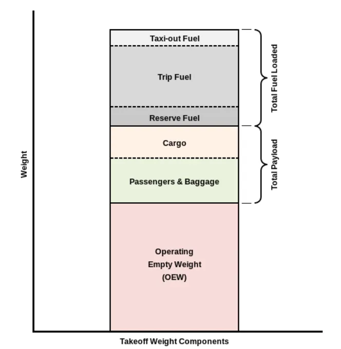
The following image depicts takeoff weight components.
|
Type |
MTOW [kg] |
MLW [tons] |
|
640,000 |
591.7 |
|
|
589,670 |
||
|
575,000 |
394 |
|
|
447,700 |
346.091 |
|
|
443,613 |
306.175 |
|
|
412,770 |
295.742 |
|
|
Antonov An-124-100M |
405,060 |
330 |
|
396,900 |
295.742 |
|
|
381,000 |
288.417 |
|
|
377,840 |
285.700 |
|
|
377,840 |
260.320 |
|
|
371,950 |
240 |
|
|
367,400 |
256 |
|
|
347,800 |
260.816 |
|
|
351,800 |
251.29 |
|
|
347,450 |
223.168 |
|
|
340,200 |
265.300 |
|
|
308,000 |
233.5 |
|
|
299,370 |
237.683 |
|
|
297,550 |
213.00 |
|
|
276,700 |
190 |
|
|
273,300 |
185 |
|
|
270,000 |
175 |
|
|
270,000 |
195.04 |
|
|
256,280 |
183 |
|
|
254,000 |
192.777 |
|
|
254,000 |
201.849 |
|
|
253,500 |
181 |
|
|
250,000 |
175 |
|
|
242,000 |
185 |
|
|
242,000 |
180 |
|
|
231,300 |
166.92 |
|
|
228,000 |
172.365 |
|
|
211,400 |
||
|
208,000 |
175 |
|
|
204,000 |
158.758 |
|
|
192,000 |
140 |
|
|
187,000 |
136.08 |
|
|
185,000 |
111.1 |
|
|
163,000 |
138 |
|
|
159,000 |
136.078 |
|
|
157,000 |
124 |
|
|
152,000 |
151.9 |
|
|
151,000 |
97.5 |
|
|
151,000 |
112.1 |
|
|
147,000 |
||
|
142,000 |
123 |
|
|
141,000 |
122 |
|
|
140,000 |
||
|
125,000 |
||
|
124,000 |
101.6 |
|
|
117,000 |
86.3 |
|
|
116,000 |
89.9 |
|
|
106,000 |
79.5 |
|
|
104,000 |
79.5 |
|
|
104,000 |
80 |
|
|
104,000 |
87.5 |
|
|
87,500 |
||
|
85,000 |
66.36 |
|
|
85,000 |
71.35 |
|
|
84,000 |
70.1 |
|
|
Airbus A321-100[17] |
83,000 |
77.8 |
|
79,000 |
65.32 |
|
|
78,000 |
68.1 |
|
|
73,000 |
63.28 |
|
|
72,500 |
62.4 |
|
|
72,500 |
62.4 |
|
|
71,000 |
64.41 |
|
|
70,700 |
||
|
70,000 |
58.06 |
|
|
Airbus A320-100[17] |
68,000 |
66 |
|
68,000 |
54.9 |
|
|
68,000 |
||
|
67,000 |
||
|
66,000 |
54.66 |
|
|
65,000 |
57.61 |
|
|
65,000 |
||
|
64,000 |
62.5 |
|
|
63,000 |
51.7 |
|
|
60,000 |
49.9 |
|
|
59,000 |
50.80 |
|
|
59,000 |
57.5 |
|
|
55,000 |
47.174 |
|
|
55,000 |
||
|
54,000 |
||
|
50,000 |
46.265 |
|
|
50,000 |
||
|
48,600 |
||
|
48,500 |
||
|
48,000 |
43 |
|
|
46,000 |
||
|
46,000 |
39.95 |
|
|
44,000 |
||
|
42,000 |
36.74 |
|
|
39,000 |
||
|
37,500 |
32.8 |
|
|
36,500 |
33.345 |
|
|
36,000 |
32.8 |
|
|
33,000 |
30.39 |
|
|
33,000 |
||
|
30,400 |
||
|
28,000 |
28.01 |
|
|
23,000 |
21.319 |
|
|
22,800 |
22.35 |
|
|
22,800 |
21.5 |
|
|
22,000 |
19.3 |
|
|
18,600 |
18.3 |
|
|
13,150 |
12.930 |
|
|
11,500 |
11.25 |
|
|
10,890 |
10.570 |
|
|
9,752 |
8.709 |
|
|
8,300 |
7.665 |
|
|
8,150 |
7.65 |
|
|
7,765 |
7.605 |
|
|
7,761 |
7.103 |
|
|
7,000 |
||
|
4,800 |
4.43 |
MTOW-Maximum Take off weight
MLW-Maximum Landing Weight
2. Is there any difference between ground speed and air speed?
ANS:
Generally speaking, there are two different types of speed when talking about airplanes: ground speed and airspeed.
GROUND SPEED:
Ground speed is the airplane’s speed relative to the surface of the Earth
AIR SPEED:
Airspeed – at least true airspeed – is its speed relative to the air it is flying in.
The relationship between airspeed and ground speed is fairly simple. Ground speed is simply the sum of airspeed and wind speed.
Airspeed = Ground Speed - Wind Speed
Effect of wind speed:
If the aircraft is flying in the same direction as the wind is blowing, the aircraft experiences tailwind, and its ground speed is higher than its airspeed.
On the other hand, if the wind is blowing against the direction the aircraft is traveling in, the aircraft experiences headwind, and its ground speed is lower than its airspeed.
The risks which may arise from engine ground running relate to the potential for loss of control of the aircraft by those persons occupying the pilot seats in the flight deck. Unwanted consequences from such static running are mainly related to those arising from the unintended movement of the aircraft during engine running - effectively a loss of control - especially during high power engine running. Damage can occur to the aircraft itself, other aircraft nearby or to airside structures. In addition, there is a risk of injury to ground support personnel who may be in relatively close proximity to the aircraft.
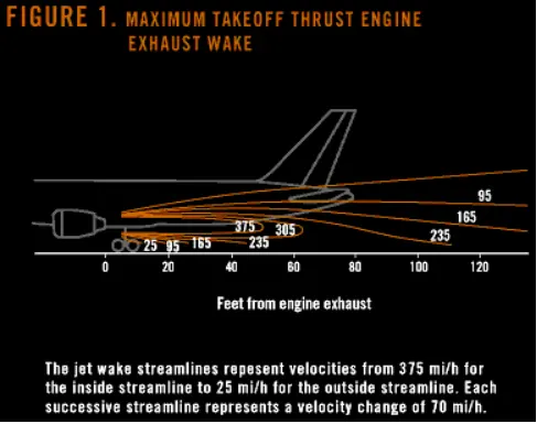
When modern jet engines are operated at rated thrust levels, the exhaust wake can exceed 375 mi/h (325 kn or 603 km/h) immediately aft of the engine exhaust nozzle. This exhaust flow field extends aft in a rapidly expanding cone, with portions of the flow field contacting and extending aft along the pavement surface (fig. 1). Exhaust velocity components are attenuated with increasing distance from the engine exhaust nozzle. However, an airflow of 300 mi/h (260 kn or 483 km/h) can still be present at the empennage, and significant people and equipment hazards will persist hundreds of feet beyond this area. At full power, the exhaust wake speed can typically be 150 mi/h (130 kn or 240 km/h) at 200 ft (61 m) beyond the airplane and 50 to 100 mi/h (43 to 88 kn or 80 to 161 km/h) well beyond this point.
High engine thrust during maintenance activity can cause considerable damage to airplanes and other elements in the airport environment.
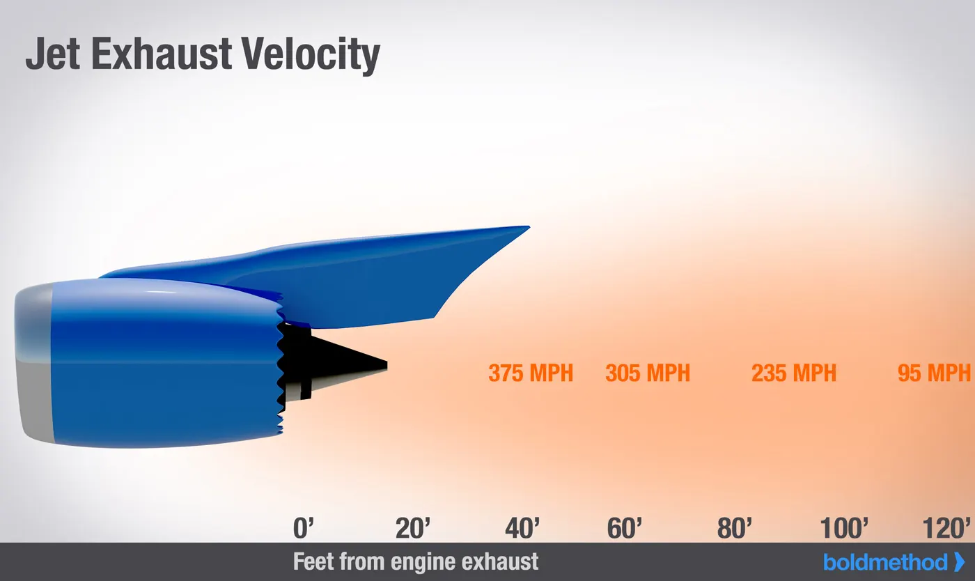
The extensive noise arises from the engine power also dangerous for humans and other living things around the vicinity.
Hence for the above reasons it is not recommended to use engine power to move on the ground.
Foreign Object Damage:
Foreign object damage (FOD) caused by high engine thrust can affect airport operations as it relates to
- Airplane structure.
- Flight controls.
- Equipment and personnel.
4. How an aircraft is pushed to runway when its ready to take off?
ANS:
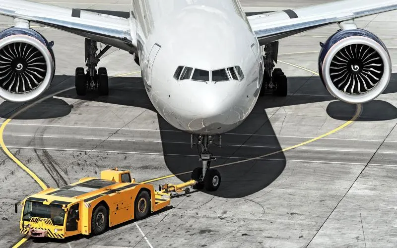
Pushback tractor is also used for repositioning the aircraft from one aircraft stand to another at an airport. Such a requirement arises when let’s say an aircraft brings international passengers to an airport gate, however, its departure flight is with domestic passengers.
Since airports have different gates for domestic and international passengers, after passenger deplaning is complete on international gate, the aircraft needs to be pushed back from international gate and taken to a domestic gate. A pushback tractor is used for such a movement because it is not economical to turn on jet engines for such a short movement.
The forward movement of an aircraft, usually with engines off, using the power of a specialised ground vehicle attached to or supporting the nose landing gear. It may occur for the movement of both in service and out of service aircraft. This will affect the promulgation of procedures and the required qualification for those occupying the flight crew seats on the aircraft during the manoeuvre. As part of out of service repositioning of aircraft supervised by maintenance personnel, it may follow the Pushback from a nose-in gate of an empty aircraft with engines off.
The Procedure for towing a aircraft:
Once the person in charge on the flight deck of the aircraft has given their confirmation of ‘brakes released’ to the person in charge of the ground crew vehicle who are to carry out the tow, the ground crew become responsible for the safe manoeuvring of the aircraft in accordance with any ATC Clearance which may be required and as may have been specifically agreed beforehand.
Unless the manoeuvre is taking place outside the movement area controlled by ATC, an RTF clearance to carry it out will be required. If the aircraft is being towed to a start position or to a Push and Hold location, this normally will be obtained by the aircraft commander or other person on the flight deck. If an out of service aircraft is being repositioned, the clearance will normally be obtained by the operator of the tow vehicle. The prescribed RTF phraseology for obtaining clearance to tow is contained in ICAO PANS-ATM (Doc 4444) and ICAO Manual of Radiotelephony (Doc 9432).
Formerly, almost all aircraft types required that the ground locking pin be installed in at least the nose landing gear during any towing operation but this is no longer always the case. If a gear ground lock pin is installed for the tow, it may need to be removed after the completion of the manoeuvre. When any ground locking pins are fitted to an aircraft for towing (or any other purposes) or when they are subsequently removed, it is usual to require the recording of such action in the Aircraft Technical Log.
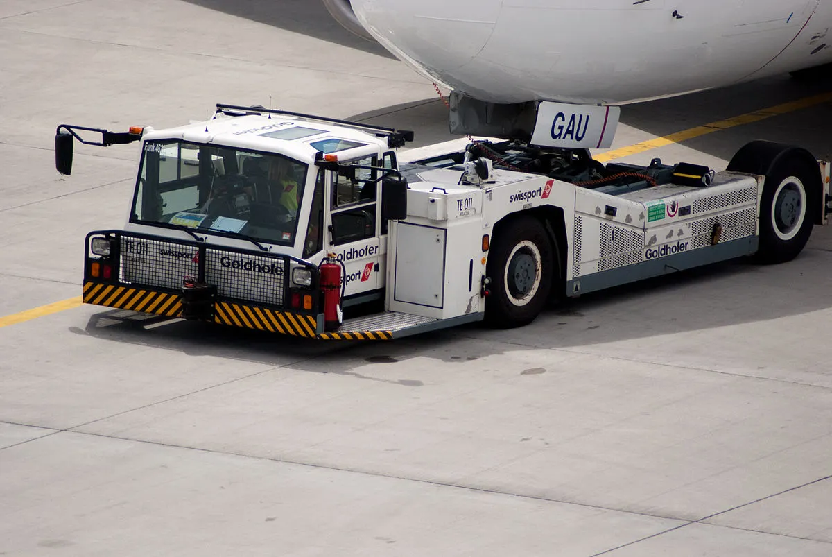
The ‘traditional’ method of allowing the ground vehicle to move an aircraft is to attach it to the aircraft nose landing gear by means of a towbar. These must be approved for use with a particular aircraft type and clearly marked as such since there is no universal towbar specification. An alternative method which is becoming more common for towing is the use of a specialised vehicle called a ‘towbarless tug’. This positions two low level ‘arms’ either side of the aircraft nose landing gear and these are used to engage with the aircraft gear leg and raise it slightly off the ground.
5. Learn about take off power, tyre design, rolling resistance, tyre pressure, brake forces when landing.
ANS:
Take off Power:
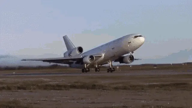
On take-off, in order to position the aircraft to a safe height away from terrain and obstacles (i.e. a flight path of maximum height and minimum ground distance desired), the engine thrust is set to a high ‘take-off power’ setting (although this is not necessarily full power) and the aircraft attitude is pitched up to maintain a specific speed (usually in the region of V2 + 15kts). Once the ‘safe height’ is reached the engine thrust can therefore be reduced to a more appropriate (i.e. efficient) setting and the aircraft flight path can be changed to a more appropriate (i.e. efficient) flight path.
In order to achieve that described above and also to provide minimum noise disturbance to the area surrounding the airport, regulatory procedures require aircraft to fly one of the two profiles given below during every departure. The aerodrome briefing pages will state which one of the two profiles is to be flown at each particular airport:
- At 1,500ft aal reduce thrust to climb power and accelerate the aircraft towards 250 knots, retracting flaps and slats.
Tyre Design:
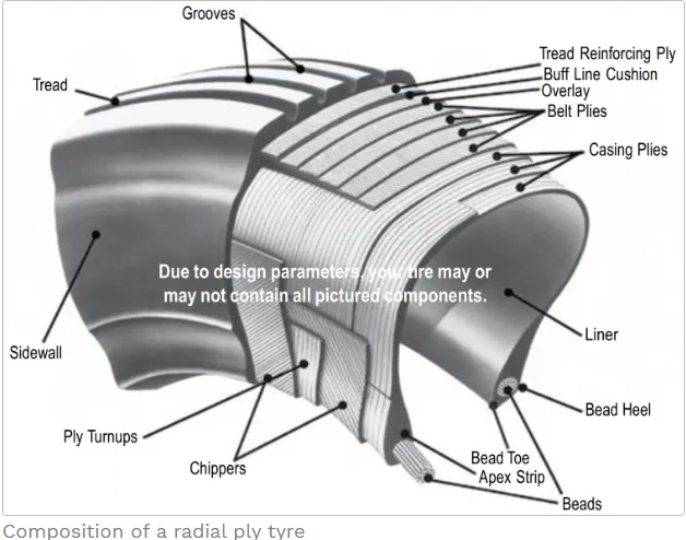
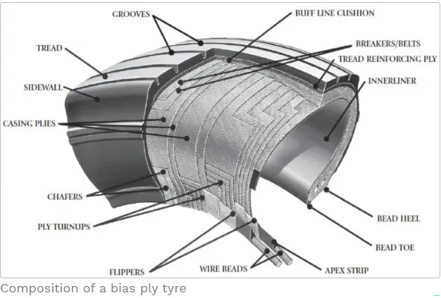
Based on the type of plies used the tyres can be:
Radial ply tires - these tyres feature a flexible casing which is constructed of rubber-coated ply cords which extend around the beads and are substantially at 90° to the centerline of the tread. The casing is stabilized by an essentially inextensible circumferential belt.
Bias ply tires - these tyres feature a casing which is constructed of alternate layers of rubber-coated ply cords which extend around the beads and are at alternate angles substantially less than 90° to the center line of the tread.
Based on the method for containing the inflation gas the tyres can be:
- Tube-type tyres - these require tubes for inflation retention.
- Tubeless tyres - these do not require tubes. They are constructed with an innerliner (integral rubber lining that is engineered to prevent the diffusion of the inflation gas into the casing.).
Rolling Resistance:
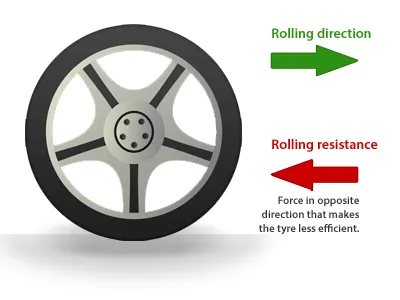
The resistance offered by the tyres against motion of vehicle/aircraft is called as rolling resistance, the rolling resistance is produced during take off/landing in the runway.
Tyre Pressure:
Aircraft tires are usually inflated with nitrogen to minimize expansion and contraction from extreme changes in ambient temperature and pressure experienced during flight. Dry nitrogen expands at the same rate as other dry atmospheric gases (normal air is about 80% nitrogen), but common compressed air sources may contain moisture, which increases the expansion rate with temperature.
Tests of airliner aircraft tires have shown that they are able to sustain pressures of maximum 800 psi (55 bar; 5,500 kPa) before bursting. During the tests the tires have to be filled with water, to prevent the test room being blown apart by the energy that would be released by a gas when the tire bursts.
The main landing gear on the Concorde was typically inflated to 232 psi (16.0 bar), whilst its tail bumper gear tires were as high as 294 psi (20.3 bar). The high pressure and weight load on the Concorde tyres were a significant factor in the loss of Air France flight 4590
Brakes Forces When Landing:
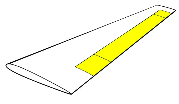
In general, when the wheels touch the ground, a set of spoilers raise up quickly, which kills the lift provided by the wings. (There are two sets seen in the image below: ground spoilers that only deploy on landing, and spoilers that are used in flight as speed brakes as well as on landing.) While the spoilers provide some drag, their primary purpose is to stop the plane from actually flying, putting all of the weight on the landing gear and in turn making the brakes that much more effective.
Aircraft have highly-engineered, multi-disc brakes made of a carbon-steel material. Manufacturers include Honeywell and Goodrich, part of Collins Aerospace. In general, the brakes are composed of discs that rotate with the wheel and separate discs that are fixed. When pressure is applied—and below you see pressure applied from the right fixed disc on all of the discs—the entire assembly compresses to create the braking action. Carbon brakes are standard today; they cool faster than steel brakes (their predecessor) and can weigh up to 700 pounds less. That represents a significant weight saving for airlines.
Auto Brakes:
Wheel brakes are usually selected to engage automatically after landing. These are called “autobrakes”.that all airliners have several levels of autobrake “severity”. The crew will decide which is the most appropriate to use for every landing depending upon factors like the length of runway, if it is wet or dry, or if the pilots want to exit the runway at a particular point. “For a short wet runway you might select autobrake 3, or MED on the Airbus. For a long dry runway you might select autobrake 1 or LOW on the Airbus".
Part B:
6. A. With necessary assumptions, calculate the force and power required to push / pull an aircraft by a towing vehicle.
ANS:
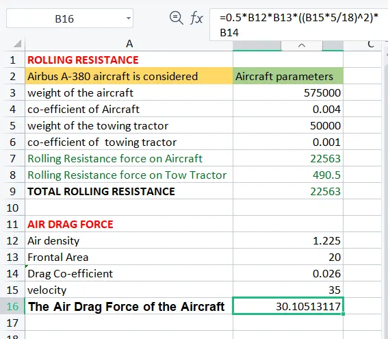
Due to Runway driving conditions, Hill climbing force is assumed as zero.
As per the assumed values, we required 245KW is required power. In addition with the suitability and the nearby value of standared HP rating, the machine (either PMDC,BLDC or IM) can be choosen to drive the Towing Vehicle.
The Total Force that the Motor needs to overcome in order to push/pull the Aircraft = 30.10KW
The Power Required-
The power required by the motor is given by the velocity with which the towing operation takes place.
The average speed of push/pull = 20 kmph = 5.5m/s
Power required by the motor = Total Force*Velocity = 30.10*5.5
Power Required by The Motor = 165.55kw
The torque output of the towing tractor can also be calculated by the below steps-
`F_(te) = T.G/r`
Where,
`F_(te)` = The Total Tractive Force(Rolling resistance force + Air drag force)
T = Torque Output
r = Radius of Tire
G = Gear Ratio
For Heavy Duty Towing Tractor we Assume,
G = 11(for delivering high torque)
r = 25inches = 0.635m
`T = F_(te)*r/G = 23000*0.635/11`
The Torque required to Push/Pull for the above stated condition = 1.327 KNm
B. Develop the model for the calculated force and power using Simulink.
Ans:
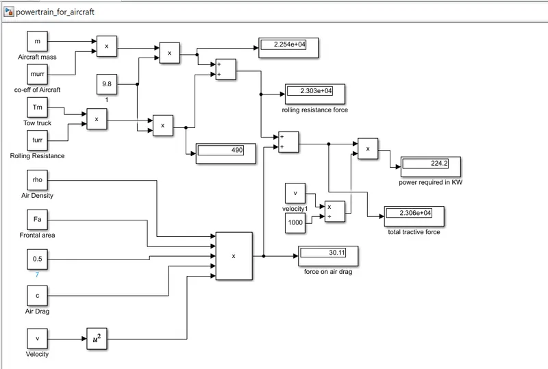
PARAMETERS:
m=575000;
Tm=50000;
murr=0.004;
turr=0.001:
ro=1.225;
Fa=20;
c_d=0.026;
ve=35/3.6:
7. A. Design an electric powertrain with type of motor, it’s power rating, and energy requirement to fulfill aircraft towing application in Simulink. Estimate the duty cycle range to control the aircraft speed from zero to highest. Make all required assumptions. Prepare a table of assumed parameters. Draw a block diagram of powertrain.
ANS:
tyre radius = r = 25inches = 0.635m
torque required at wheels = total force x radius
=1.327 *0.635
=0.842KNm
motor torque = wheel torque /gear ratio * efficiency
G = 11(for delivering high torque)
=0.842/11*0.82
assumed efficiency = 82%
Motor torque=0.0627KNm
The Power Required-
The power required by the motor is given by the velocity with which the towing operation takes place.
The average speed of push/pull = 20 kmph = 5.5m/s
Power required by the motor = Total Force*Velocity = 30.10*5.5
Power Required by The Motor = 165.55kw
Energy = power*time
=165.55*0.50
Energy =49.665 KWh
Therefore the battery must be able to store the energy 60kwh and should deliver the energy throughout the run time in order for the motor to produce the 1.32 KNm of torque instantaneously. Thus the storage of energy in batteries with high performance Ultracapacitors are selected to fulfill the required power deliver.
therefore,the duty cycle range is control the speed from zero to high speed
D=required power/rated power
D=49.665/60
D=0.83
this means the duty cycle range is 83 %
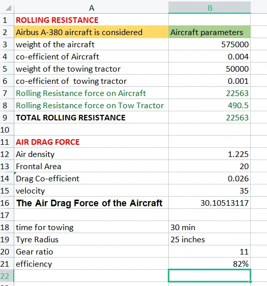
-The paramter values were assumed and the result was obtained for the towing vehicles force required to pull or push the aircraft.
simulink model: