Week-6 Challenge: EV Drivetrain
Aim:
- To get to know the types of converters used in HEV and EV vehicles.
- To find the speed using torque-speed relation.
- To get to know about induction and DC brushless motors.
question:
1. Which types of power converter circuits are employed in electric and hybrid electric vehicle?
Power Electronic Converters: -
In Electric and Hybrid Electric Vehicles (EV/HEV), the power electronic converters are considered as the key elements that interface their power sources to the drivetrain of the EVs. In order to design highly efficient converters for the EV’s power system, advanced DC/DC and DC/AC converters are required to adapt the output voltage and current levels with high power quality.
The 3 types of converters which are widely used in an Electric Vehicle are:
DC - DC CONVERTER:
In electric engineering, a DC to DC converter is a category of power converters and it is an electric circuit which converts a source of direct current (DC) from one voltage level to another, by storing the input energy temporarily and then releasing that energy to the output at a different voltage. The storage may be in either magnetic field storage components (inductors, transformers) or electric field storage components (capacitors).
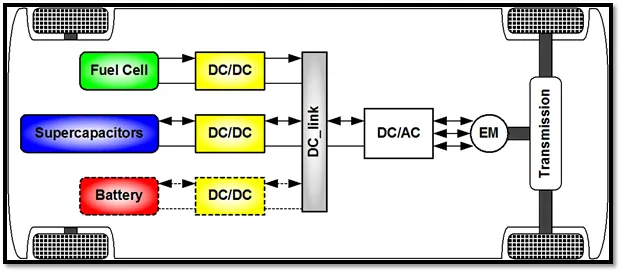
DC-DC converters in an electric vehicle may be classified into unidirectional and bidirectional converters. Unidirectional DC-DC converters cater to various onboard loads such as sensors, controls, entertainment, utility, and safety equipment. They are also used in DC motor drives and electric traction. Bidirectional DC-DC converters find applications in places where battery charging, regenerative braking, and backup power are required. The power flow in a bidirectional converter is usually from a low voltage end such as a battery or a supercapacitor to a high voltage side and is referred to as boost operation.
During regenerative braking, the power flows back to the low voltage bus to recharge the battery (buck mode). As a backup power system, the bidirectional DC-DC converter facilitates the safe operation of the vehicle when ICEs or electric drives fail to drive the motor. Due to the aforementioned reasons, high-power bidirectional DC-DC converters have gained a lot of importance in the recent past.
The converter topologies are classified as:
- Buck Converter:
The buck converter is a step-down converter and produces a lower average output voltage than the dc input voltage.
- Boost converter:
In the boost converter, the output voltage is always greater than the input voltage.
- Buck-Boost converter:
In a buck-boost converter, the output voltage can be either higher or lower than the input voltage.
- Cuk converter:
The output voltage can be either higher or lower than the input voltage providing some advantages over buck-boost (like a continuous current, less current ripple etc.)
- SEPIC converter:
The output voltage can be either higher or lower than the input voltage (with no polarity reversal compared to Buck-boost or Cuk converter).
AC – DC Converter (On Board Charger): -
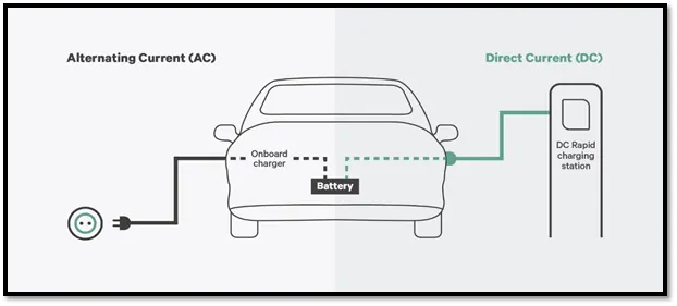
AC to DC converters are most commonly used in Plug-in Hybrid Electric Vehicles (PHEV) & Plug-in Electric Vehicles (PEV). These vehicles get their propulsion power from an external electricity source (charging stations) which is alternating current. The battery needs to be charged using a direct current source. For this purpose, AC to DC converter is employed in a PHEV & PEV.
Electric power is transported on wires either as a direct current (DC) flowing in one direction at a non-oscillating constant voltage, or as an alternating current (AC) flowing backwards and forwards due to an oscillating voltage. AC is the dominant method of transporting power because it offers several advantages over DC, including lower distribution costs and simple way of converting between voltage levels thanks to the invention of the transformer.
AC power that is sent at high voltage over long distances and then converted down to a lower voltage is a more efficient and safer source of power in homes. Depending on the location, high voltage can range from 4kV (kilo-volts) up to 765kV. As a reminder, AC mains in homes range from 110V to 250V, depending on which part of the world you live it. In the U.S., the typical AC main line is 120V.
AC-DC Converters steer an alternating current, as its voltage also alternates, into reactive impedance elements, such as inductors (L) and capacitors (C), where it is stored and integrated. This process separates the power associated with the positive and negative potentials.
DC-AC converters (Inverters)
An inverter is a device that converts DC power from the battery to AC power in an electric vehicle motor. The inverter can change the speed at which the motor rotates by adjusting the frequency of the alternating current.
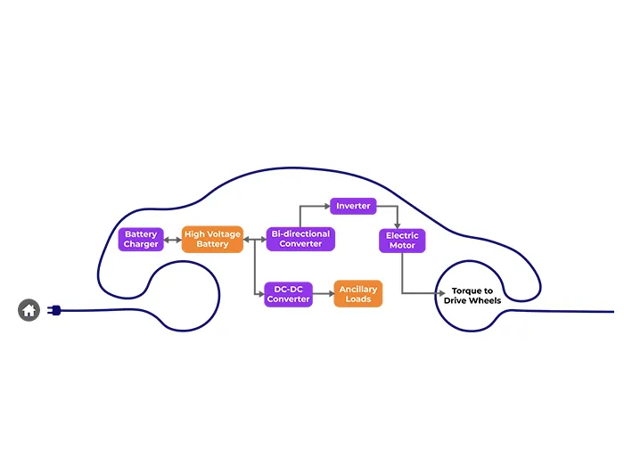
The Significance of DC/AC Converters
The use of inverters can increase or decrease the power or torque of the motor by adjusting the amplitude of the signal.
It plays a significant role in capturing energy from regenerative braking and feeding it back to the battery. The key component is that it has a direct impact on on-road performance, driving range, and reliability of the vehicle also as a consequence of their weight and size.
The output voltage waveform of ideal inverters should be sinusoidal. However, the waveform of practical inverters is non-sinusoidal and contains certain harmonics.
QUESTION 2:
2. An Electric Vehicle's powertrain with 72V battery pack in shown in the diagram below. The duty ratio for acceleration operation is 'd1' and for the braking operation the duty ratio is 'd2'.
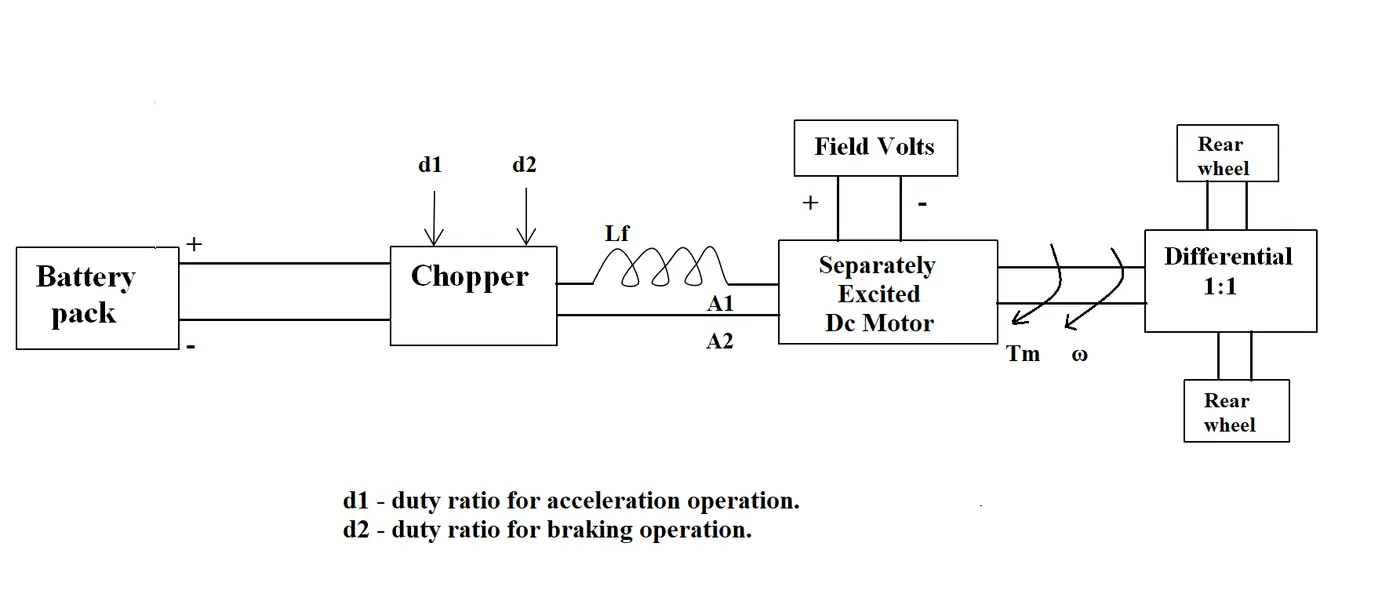
The other parameters of the electric vehicle is given below,
Motor and Controller Parameters:
Rated Armature voltage= 72 V
Rated armature current= 400 A
Ra= 0.5Ω, KΦ= 0.7 Volt second
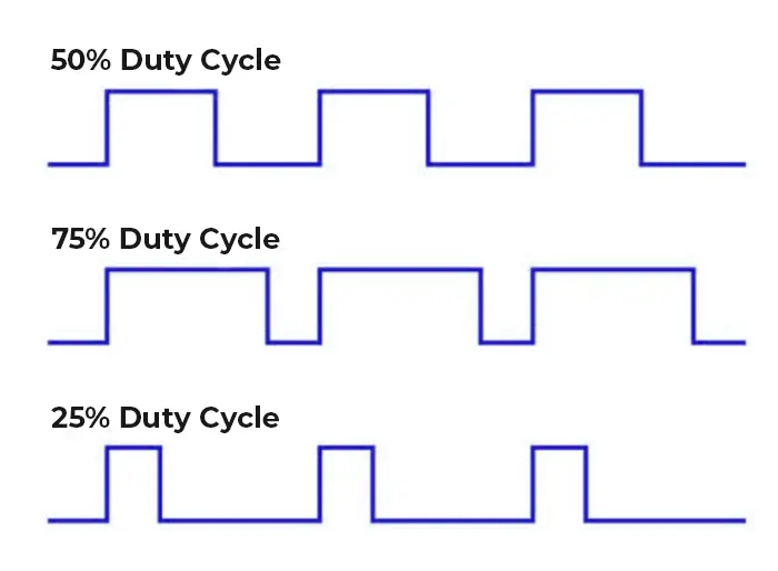
Chopper Switching frequency= 400 Hz
The vehicle speed-torque characteristics are given by the below equation

What is EV steady state speed if duty cycle is 70%?
GIVEN:
The following input parameters are given: -
Battery pack voltage (V) = 72V
Rated armature current = 400 A
Armature Resistance (Ra) = 0.5Ω
Motor constant (KΦ) = 0.7
Chopper Switching frequency= 400 Hz
Duty Cycle = 70%
As the torque formula is given, we need to find the speed in rad/sec. Use the other expression available which is given below:
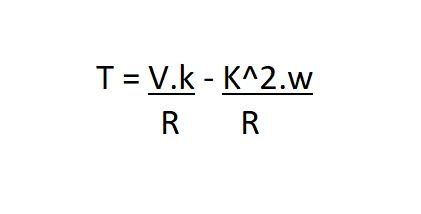
T= torque
V = armature voltage
R = resistance
w = speed rad/sec
Compare the two equations:
24.7 + 0.0051*w^2 = ((v*k)/R) - ((k^2)*w/R)
24.7 + 0.0051*w^2 = (72*0.7)/0.5 - (0.7^2/0.5)*w
70.56 - 0.98*w = 24.7 + 0.0051*W^2
w^2 + 192.15*w - 8992.15 = 0
In order to find the roots use following formula

a=1:
b=192.15:
c=8992.15:
And this values are used in the above quadratic equation and below following roots are got
x=38.9159:
x=−231.066
As the speed value can not be negative.So,we are taking only positive value
Steady state speed of vehicle = 38.95 rad/sec
and the rpm is = 371.94 rpm
QUESTION 3:
3. Develop a mathematical model of a DC Motor for the below equation using Simulink.
ω= V/Kϕ-Ra/Kϕ^2 .T
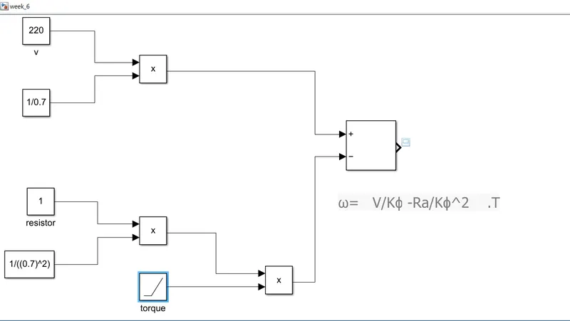
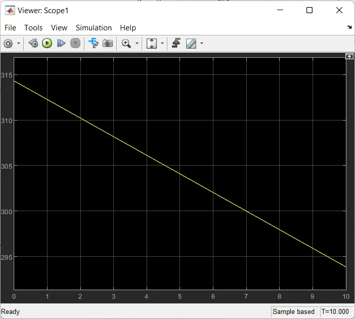
For the given equation the mathematical model is been derived and created a simulink model. the created model is attached above and for the model the value are given as
v=220;
motor constant as 0.7;
armature resistance is 1;
And for torque ramp block is used and the given plot is attached above.when we seeing the plot the torque is inversely proportional to speed
when supply voltage (V) is constant, torque (T) is inversely proportional to speed (ω).
By refering to the below picture when the speed increases the torque is gradualy decreasing
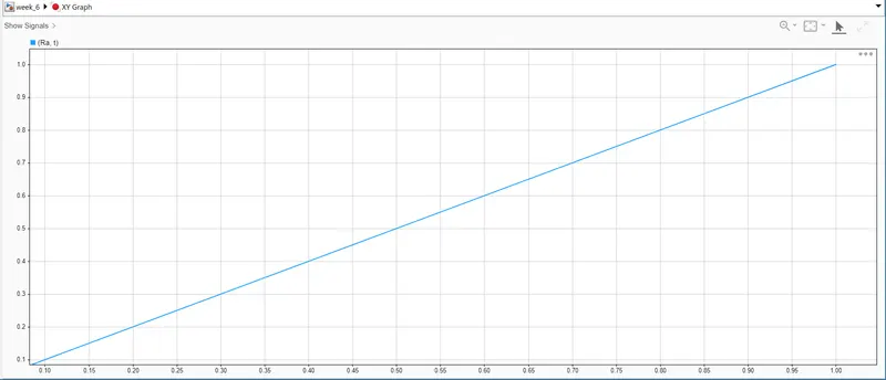
As you can see here a XY graph that plots the value of armature resistance and torque
So,the torque(t) is Directly proportional to the armature resistance (Ra).
QUESTION 4:
4. Refer to the blog on below topic:
Induction Versus DC brushless motors by Wally Rippel, Tesla
Explain in brief about author’s perspective.
The following points can be concluded from the above topic:
- In the beginning, author describes the dominance of Internal Combustion Engines (ICE) in the world of automobile industry and also discuss different types of engines. He explains that all engines were similar and it was up to the user to select according to their requirement. He also speaks about induction motor and brushless DC motors and presents his view that these two technologies will be widely used for the coming years.
- Then he explains the working of both 3-phase induction motor and a brushless DC motor.
- Now the author has done comparison between these two technologies and stated some advantages and disadvantages of each.
- Induction motor have some advantages like: it has no magnets. The motor has the ability to start under load. No inverter is needed. Some disadvantages of Induction motors are: They cannot operate from DC; AC is a must. Shaft speed is proportionate to line frequency. Hence, when used with utility power, they are constant speed machines. When operated from utility power, they have limited starting torque and somewhat limited running peak torque capabilities, when compared to DC type machines.
- Brushless DC motor have some advantages like: much less rotor heat is generated with the DC brushless drive. The peak point energy efficiency for a DC brushless drive will typically be a few percentage points higher than for an induction drive. Some disadvantages of Brushless DC motor are: as machine size grows, the magnetic losses increase proportionately and part load efficiency drops. Permanent magnets are expensive and difficult to handle due to very large forces that come into play when anything ferromagnetic gets close to them.
DC Brushless Induction motor require an absolute position sensor require an absolute position sensor less rotor heat is generated ,Rotor cooling is easier and peak point efficiency higher.
operate at unity power factor
power factor is about 85 %,
peak point efficiency higher compare to DC Brushless
strength of the magnetic field produced by the permanent magnets would be adjustable.
to get max torque the magnetic field should max at low speed maintained by the inverter and motor current low
no magnets and B fields are “adjustable,” since B is proportionate to V/f (voltage to frequency).efficiency is maximized due to low magnetic losses Average efficiency is low Average efficiency is high Permanent magnets are expensive no magnet there is advantage in cost they are easy to control The control laws are more complex and difficult to understand, so difficult to control with saying "Still No Winner",he describe that no one is best DC brushless or induction.
He concluded that both are the best as per the requirement.