Project - Speed Control of a Direct Current (DC) motor
Speed Control of a Direct Current (DC) motor:
The block diagram of a simple PID controller is provided in the figure below,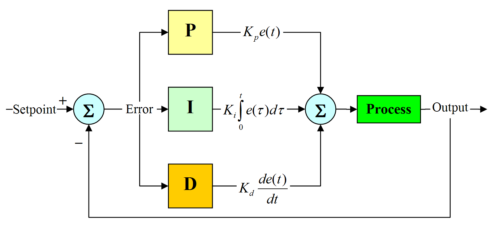
A common actuator in control systems is the DC motor. It directly provides rotary motion and, coupled with wheels or drums and cables, can provide translational motion. The electric circuit of the armature and the free-body diagram of the rotor are shown in the following figure:
%DESIGN PARAMETERS
Jm=0.01; %Momentt of inertia of rotor
Bm=0.1; %Motor viscous friction constant
Km=0.01; %Back EMF constant
Kt=0.01; %Motor torque constant
Ra=1; %Armature Resistance
La=0.5; %Armature Inductance
%PD Design
A=[-Bm/Jm Kt/Jm;-Km/La -Ra/La];
B=[0;1/La];
%pole placement design
fn=1;
wn=2*pi*fn;
zeta=0.5;
p1=-zeta*wn+wn*sqrt(zeta^2-1);
p2=-zeta*wn-wn*sqrt(zeta^2-1);
p=[p1;p2];
k=place(A,B,p);
kp=20;
kd=-1;
ki=4;
%Plotting the graphs from dc_motor_plot.m file
figure(1)
subplot(321);plot(out.time,out.ia,'b-');grid;title('ARMATURE CURRENT(A)');
subplot(322);plot(out.time,out.w,'g-');grid;title('SPEED(Rad/s)');hold;
subplot(322);plot(out.time,out.ref,'g-');grid;
subplot(323);plot(out.time,out.t,'k-');grid;title('TORQUE(Nm)');
subplot(324);plot(out.time,out.vb,'r-');grid;title('BACK EMF(Vb)');
subplot(325);plot(out.time,out.u,'y-');grid;title('CONTROL(U)');
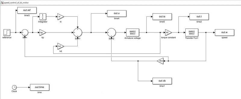
SIMULINK MODEL FOR SPEED CONTROL FOR DC MOTOR WITH PID CONTROLLER:
OUTPUT:
kp=38.3133;
ki=10;
kd=-2.8584;
Reference speed=55;
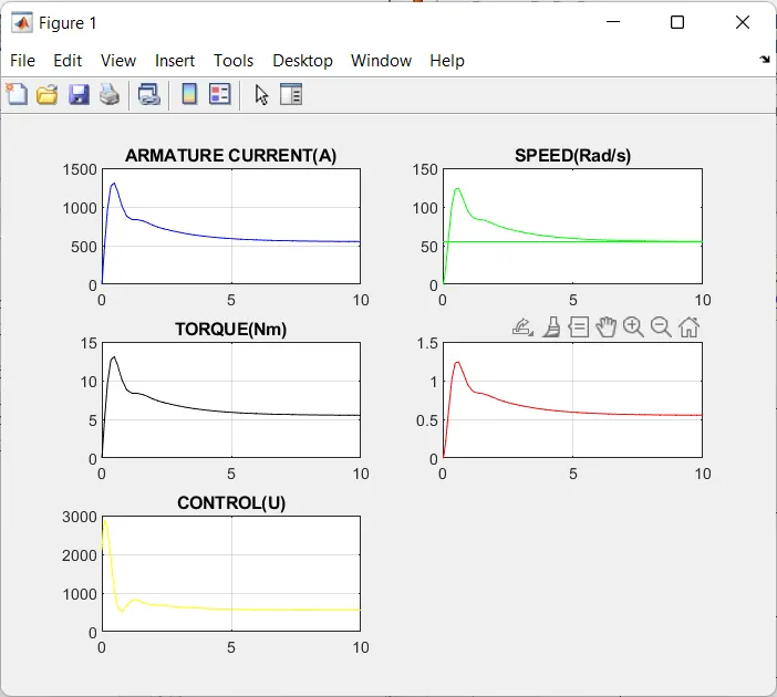
kp=38.3133;
ki=10;
kd=-2.8584;
reference speed=5;
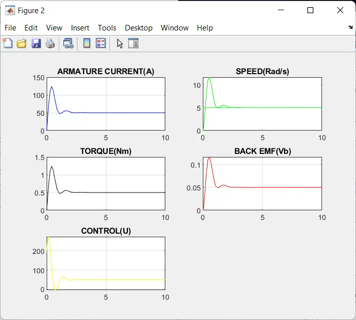
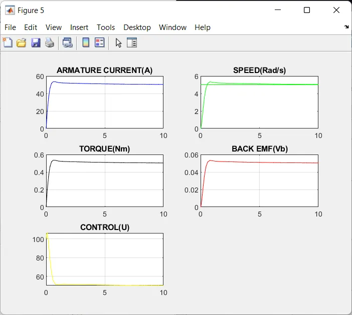
TO REDUCE THE OVERSHOOT, THE Kd VALUE IS DECREASED TO -1.
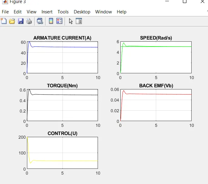
TO REDUCE THE OVERSHOOT FURTHER,THE Kp VALUE IS DECREASED
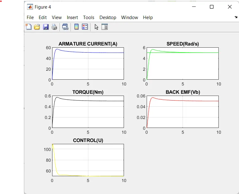
ON FURTHER DECREASING THE Ki VALUE TO 4,THE DESIRED CHARACTERISTICS IS OBTAINED AND IS ATTACHED BELOW.