Project-1: Powertrain for aircraft in runways
Part A:
1. Search and list out the total weight of various types of aircrafts.
- An aircraft is a vehicle or machine that is able to fly by gaining support from the air. It counters the force of gravity by using either static lifts or by using the dynamic lifts of an airfoils, or in a few cases the downward thrust from jet engine. Common examples of aircraft include airplanes, helicopters, airships (including blimps), gliders,paramotors, and hot air ballaon.
-
The maximum allowable weight for an aircraft is determined by design considerations. The manufacturer provides the aircraft operator with the empty weight of the aircraft and the location of its empty weight center of gravity (EWCG) at the time the certified aircraft leaves the factory.
-
However, the maximum operational weight may be less than the maximum allowable weight due to such considerations as high-density altitude or high-drag field conditions caused by wet grass or water on the runway. The maximum operational weight may also be limited by the departure or arrival airport’s runway length.
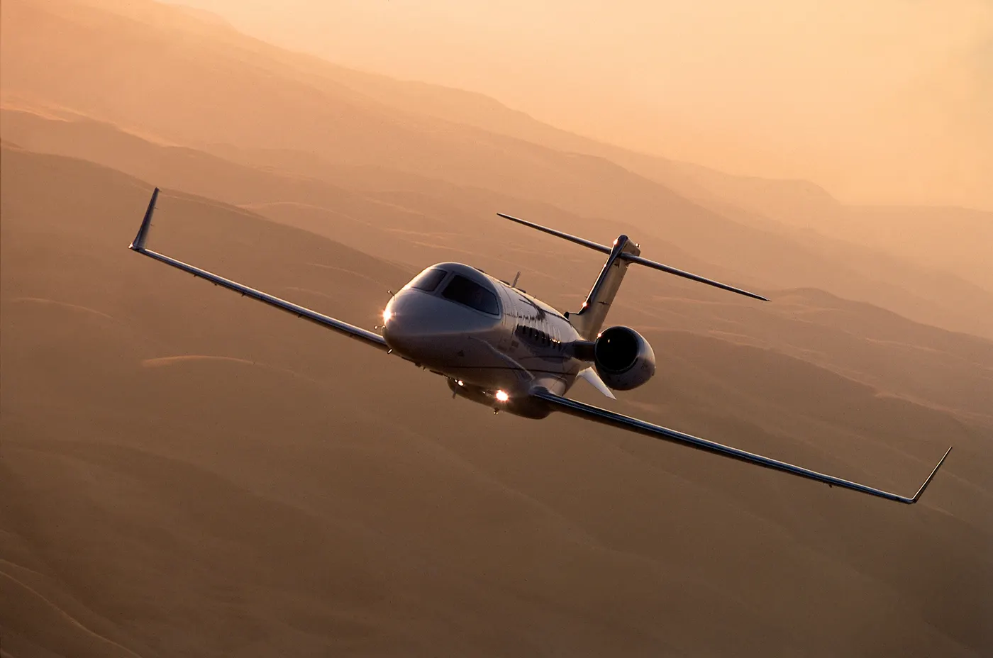
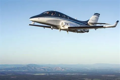
MANUFACTURER’S DESIGN WEIGHT LIMITATION
- The maximum allowable weight for an aircraft is determined by design considerations by the aircraft’s manufacturer.
- However, the maximum operational weight may be less than the maximum allowable weight due to such considerations as high-density altitude or high-drag field conditions caused by wet grass or water on the runway.
- The maximum operational weight may also be limited by the departure or arrival airport’s runway length.
- The structural weight limits are based on aircraft maximum structural capability and define the envelope for the CG charts. Aircraft structural weight capability is established during aircraft design and certification.
List of Types of the weight of aircraft:
MAXIMUM DESIGN TAXI WEIGHT (MDTW OR MTW)
The difference between the maximum taxi/ramp weight and the maximum take-off weight (maximum taxi fuel allowance) depends on the size of the aircraft, the number of engines, APU operation, and engines/APU fuel consumption, and is typically assumed for 10 to 15 minutes allowance of taxi and run-up operations.
MAXIMUM DESIGN TAKEOFF WEIGHT (MDTOW OR MTOW)
The maximum design takeoff weight is the maximum certificated design weight for takeoff run as limited by aircraft strength and airworthiness requirements.
MAXIMUM DESIGN LANDING WEIGHT (MDLW OR MLW)
The Maximum design landing weight is the maximum certificated design weight for landing limited by aircraft strength and airworthiness requirements. It generally depends on the landing gear strength or the landing impact loads on certain parts of the wing structure.
MAXIMUM DESIGN ZERO-FUEL WEIGHT (MDZFW)
The maximum design zero-fuel weight is the maximum certificated design weight of the aircraft less all usable fuel and other specified usable agents as limited by aircraft strength and airworthiness requirements.
It is the maximum weight permitted before usable fuel and other specified usable fluids are loaded in specified sections of the airplane.
The weight difference between the MDTOW and the MDZFW may be utilized only for the addition of fuel.
MINIMUM FLIGHT WEIGHT (MFW)
Minimum certificated weight for flight as limited by aircraft strength and airworthiness requirements.
AIRCRAFT GROSS WEIGHT
The aircraft gross weight decreases during flight due to fuel and oil consumption. The aircraft gross weight may also vary during flight due to payload dropping or in-flight refueling.
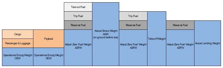
MANUFACTURER’S EMPTY WEIGHT (MEW)
Let’s start with the aircraft itself. An aircraft “as is” includes:
- Airframe structure with all moving mechanical parts (fuselage, wings, flaps, gear, rudder, nacelle …)
- Power generation system (APU, main engines, power plant…)
- Systems (electrical, hydraulics, pneumatic, fuel flow system, instrument, navigation, air conditioning, anti-ice, fixed furnishing)
- Fixed equipment and services considered an integral part of the aircraft
- Fixed ballast
- Closed system fluids
- Unused fuel only for small aircraft
This weight does not include:
- Fuel
- Oil, potable water
- Payload (Cargo, passenger, luggage)
- Removable equipment
- Customer specific installations or operator items
OPERATIONAL EMPTY WEIGHT (OEW)
ACTUAL ZERO FUEL WEIGHT (AZFW)
The payload includes:
- the passengers weight (the standard weights used defined by ICAO respectively)
- the passengers luggage’s weight
- the cargo weight
The assumed weights vary around some kg / lbs. depending on the number of seats available on the aircraft.
ACTUAL GROSS WEIGHT (AGW)
The actual gross weight is the weight of aircraft ready for departure at the gate before push-back and start-up.
TAKE-OFF WEIGHT (TOW)
The gross weight varies during flight. Fuel and oil consumption reduces the gross weight. Additionally it may vary during flight due to inflight refuelling or payload dropping.
MAXIMUM DESIGN TAKEOFF WEIGHT (MDTOW)
- The maximum takeoff weight (also known as the maximum brake-release weight) is the maximum weight authorized at brake release for takeoff, or at the start of the takeoff roll.
- The maximum takeoff weight is always less than the maximum taxi/ramp weight to allow for fuel burned during taxi by the engines and the APU.
- In operation, the maximum weight for takeoff may be limited to values less than the maximum takeoff weight due to aircraft performance, environmental conditions, airfield characteristics (takeoff field length, altitude), maximum tire speed and brake
- At this weight, the subsequent addition of fuel will not result in the aircraft design strength being exceeded. The weight difference between the MTOW and the MZFW may be utilized only for the addition of fuel.
LANDING WEIGHT
|
Manufacturer’s Empty Weight (MEW) |
36,779 kg |
|
+ Operator’s Items |
+ 5,205 kg |
|
= Operational Empty Weight (OEW) |
= 41,981 kg |
|
+ Payload |
+ 13,529 kg |
|
= Actual Zero Fuel Weight (AZFW) |
= 55,510 kg |
|
+ Fuel |
+ 13,239 kg |
|
= Actual Gross Weight (AGW) |
= 68,749 kg |
|
- Taxi Fuel |
- 100 kg |
|
= Actual Take-Off Weight (ATOW) |
= 68,649 kg |
|
Fuel consumption |
-10,900 kg |
|
= Actual Landing Weight (ALW) |
= 57,749 kg |
- Different types of Aircrafts and their weight.
- Cessna 172 – Used by many as initial training aircraft (27 feet long) – 1450lbs empty weight, 2450lbs max weight
- Citation Jet M2 – (42 feet long) – 6990lbs empty weight, 10,700lbs max weight
- Boeing 767-300 – (185 feet long) – 195,000lbs empty weight, 400,000 max weight
- Boeing 787-800 – (186 feet long) – 264,500lbs empty weight, 502,500lbs max weight
- Boeing 777-300 – (242 feet long) – 354,000lbs empty weight, 660,000lbs max weight
- Boeing 747-400 – (232 feet long) – 407,000lbs empty weight, 910,000lbs max weight
- Airbus A320 – (123 feet long) – 82,000lbs empty weight, 170,000lbs max weight
- Airbus A330 – (210 feet long) – 274,500lbs empty weight, 507,000lbs max weight
----------------------------------------------------------------------------------------------------------------------------------------------------------
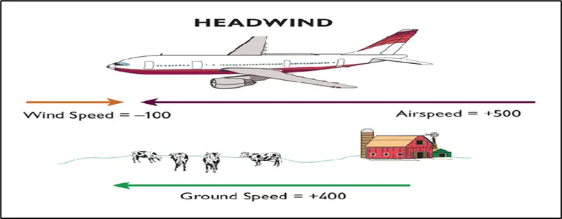
Ground speed (GS): - Ground speed is the airplane’s speed relative to the surface of the Earth.
Ground speed = air speed +wind speed (VECTOR SUM)
ground speed is what determines how fast an aircraft will get to its destination.
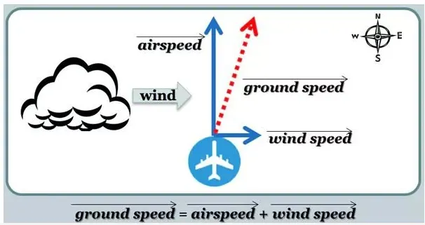
Air speed (TAS): - Air speed is the speed of airplane’s speed relative to the wind speed.
airspeed is what determines whether there is enough airflow around an aircraft to make it fly.
Wind’s Effect on Ground Speed
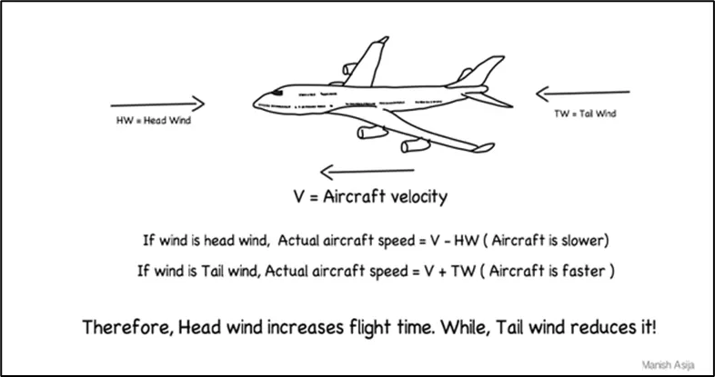
The relationship between airspeed and ground speed is fairly simple. Ground speed is simply the sum of airspeed and wind speed. If the aircraft is flying in the same direction as the wind is blowing, the aircraft experiences tailwind, and its ground speed is higher than its airspeed. On the other hand, if the wind is blowing against the direction the aircraft is traveling in, the aircraft experiences headwind, and its ground speed is lower than its airspeed.
- In case you are still unsure about the difference between airspeed and ground speed, here’s an analogy to bring the concepts “down to earth.”
- Imagine a moving walkway going from point A to point B moving at 3 miles per hour
- And, imagine you are walking on the walkway at a speed of 3 miles per hour relative to the walkway. In other words, you are moving from point A to point B at a speed of 6 miles per hour – the sum of the speed of the walkway and the speed at which you are walking relative to the walkway.
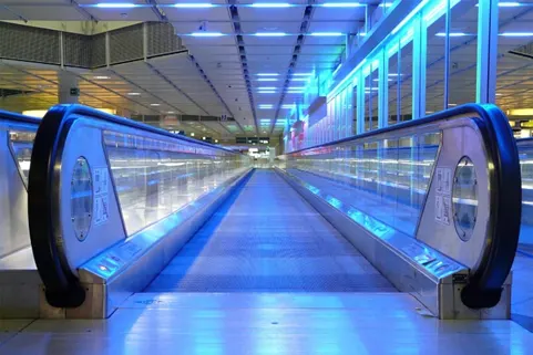
What if, though, you tried to walk on the walkway from point B to point A?
Obviously, if you walked at 3 miles per hour relative to the walkway, you would be standing still. To move, you would have to walk faster than 3 miles per hour relative to the walkway. For example, if you walked at 5 miles per hour relative to the walkway, you would be moving from point B to point A at a speed of 2 miles per hour.
Basically, there are three types of air speed which are explained below: -
Indicated airspeed is an airspeed that is calculated directly off an aircraft’s pitot-static system. It’s the calculated off the aircraft’s dynamic pressure – the difference between its total pressure and static pressure.
The dynamic pressure depends not only on the aircraft’s speed, but also on the density of the air it is flying in. As such, the higher the aircraft flies – and the lower the air density as a result – the bigger the difference between indicated and true airspeed is.
Calibrated airspeed is indicated airspeed adjusted for a variety of errors.
Just as an example, one of the things it’s adjusted for is the flap position. The reason for that is that at different flap positions, air flows differently around the pitot-static system and affects the indicated airspeed readings.
True airspeed is, as has been mentioned numerous times in this article, the actual speed at which an aircraft is moving relative to the air it is traveling in. Its calibrated airspeed adjusted for the exact conditions (altitude, air temperature, etc.) that the aircraft is flying in.
----------------------------------------------------------------------------------------------------------------------------------------------------
If an aircraft is moving by using the power of its engines then that movement is called taxiing, whereas if an aircraft is being moved without any help from its engines, it’s either being towed or pushed back.
How aircraft move on the Ground?
- Tugs
- Towbarless
- Enigine
Engines
- Once the pushback has been completed, the aircraft can move under its own power. Normally, the engines provide the thrust for the aircraft to move around and that is called Taxiing.
- An airplane uses taxiways to taxi from one place on an airport to another; for example, when moving from a hangar to the runways.
- The aircraft’s engines are started either during pushback or after pushback and only after informing the ground crew of the starting sequence.
Why not to use aircraft engine during ground operation : -
- Pilots have to be extra cautious while adding power to get the aircraft to start moving initially. There have been many instances of unsuspecting ground crew and ground equipment being hit by jet blast. In some unfortunate instances, the ground crew have also been ingested into the engine as a result of a communication breakdown between the pilots and ground crew.
- The air intake of a jet engine is powerful enough to suck in a human body. Even at a distance, the jet engine suction is strong enough to devour loose debris e.g., rags, bolts, paper, stones, catering foils, plastic cups and bags.
- Loss of control may happen on aircraft engine as power developed by engine is very very high.
-----------------------------------------------------------------------------------------------------------------------------------------------------------
4. How an aircraft is pushed to runway when its ready to take off?
How aircraft move on the Ground?
Tugs
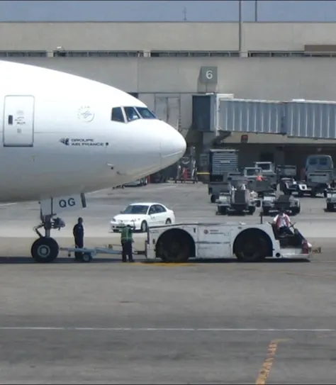
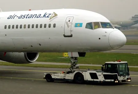
- Tugs are special, low-profile utility vehicles used to either tow an aircraft or to push them back from the terminal or remote parking stand. Most tugs utilize wide tires to provide excellent grip which is essential during push-back or towing operations. There are two main types of tugs: conventional and towbarless.
- Conventional tugs employ the use of a tow-bar which is attached to the nose wheel of the aircraft before pushback. The tow-bar acts as a giant lever and helps to rotate the nose wheel.
Towbarless
On the other hand, towbarless tugs use a hydraulic lifting mechanism to scoop up the nose wheel of the aircraft and then push it back. Towbarless tugs are preferred due to their simplicity and because they provide more precise control of the aircraft during towing and pushback operations.
Engines
Once the pushback has been completed, the aircraft can move under its own power. Normally, the engines provide the thrust for the aircraft to move around and that is called taxiing. The aircraft’s engines are started either during pushback or after pushback and only after informing the ground crew of the starting sequence.
---------------------------------------------------------------------------------------------------------------------------------------------------------
5. Learn about take off power, tyre design, rolling resistance, tyre pressure, brake forces when landing.
Take off Power
- The takeoff in any aircraft occurs when the airplane leaves the ground and becomes airborne.
- Takeoff is the first critical phase of flight pilots encounter, requiring detailed planning
- The amount of power that an engine is allowed to produce for a limited period of time for takeoff. The use of takeoff power is usually limited to 5 min for reciprocating engines and up to 2½ min for gas turbine engines
- This may not always be the case. Specifically, with respect to reciprocating engines, it is the brake horsepower developed under standard, sealevel conditions and under the maximum conditions of the crankshaft rotational speed and the engine manifold pressure approved for the normal take-off.
- It is limited in continuous use to the period of time.
- With respect to gas turbine engines, it is the thrust developed under static conditions at a specified altitude and atmospheric conditions of the rotor shaft rotational speed and gas temperature approved for the normal takeoff.
- It is limited in continuous use to the period of time shown in the approved engine specifications.
Tyre Design
-
An aircraft tire or tyre is designed to withstand extremely heavy loads for short durations.T he number of tires required for aircraft increases with the weight of the aircraft, as the weight of the airplane needs to be distributed more evenly. Aircraft tire tread patterns are designed to facilitate stability in high crosswind conditions, to channel water away to prevent hydroplaning, and for braking effect.
-
Aircraft tires also include fusible plugs (which are assembled on the inside of the wheels), designed to melt at a certain temperature. Tires often overheat if maximum braking is applied during an aborted takeoff or an emergency landing. The fuses provide a safer failure mode that prevents tire explosions by deflating in a controlled manner, thus minimizing damage to aircraft and objects in the surrounding environment.
-
Each of the twelve Boeing 777-300ER main tires is inflated to 220 psi (15 bar; 1,500 kPa), weighs 120 kg (260 lb), has a diameter of 134 cm (53 in) and is changed every 300 cycles while the brakes are changed every 2000 cycles. Each tire is worth about $5,000. Aircraft tires generally operate at high pressures, up to 200 psi (14 bar; 1,400 kPa) for airliners,
-
The four major manufacturers in aircraft tire manufacturing are the following according to a report by Pelmar Engineering in 2013:
- Goodyear (United States)
- Michelin (France)
- Dunlop Aircraft Tyres (United Kingdom)
- Bridgestone (Japan)
-
Design and Construction of Aircraft tyre
Carcass plies are used to form the tire. They are sometimes called casing plies. An aircraft tyre is constructed for the purpose it serves.
- They support the weight of an aircraft while it is on the ground.
- It also provides the necessary traction for braking and stopping of an aeroplane.
- Tyre also helps to absorb the shock of landing and provide cushioning the roughness of takeoff, roll-out, and taxi operations.
Unlike an automobile or truck tyre, it does not have to carry a load for a long period of continuous operation. However, an aircraft tyre absorbs the high impact loads of landing, and also it’s operating at high speeds for a short time when required.
Let’s go through some technical aspects of the tyre.
- Retreading – Retreading is methods of restoring a worn tyre by renewing the tread area or by renewing the tread area plus one or both sidewalls. Repairs are included in the tyre retreading process.
-
Load Rating – Load rating is the maximum permissible load at a specified inflation pressure.
-
Ply Rating – Ply Rating is used to identify the maximum recommended load rating and inflation pressure for a specified tyre. It is an index of tyre strength.
-
Speed Rating – The speed rating is the maximum takeoff speed to which the tyre has been tested.
-
Skid Depth – Skid depth is the distance between the tread surface and the deepest groove as measured in the mould.
-
Aircraft tyres must have an approved speed and load rating and have sufficient clearance when retracted through landing gear to allow for tyre growth. Tyre growth is the increase in the size of the tyre due to centrifugal forces at high speed.
-
Aircraft tyres may be Radial or Bias
-
Almost all airliners are using Radial tyre. Bias is an older design, and it’s mainly used for road vehicles. Radial tyres have the word RADIAL on the sidewall. Radial tires are more expensive than bias-ply tyres. Radial tires are in demand because of their lower life cycle cost and long term value.
Rolling resistance
- Rolling resistance is the opposing force a rolling body in motion experiences when it comes in contact with a surface.
- A rubber tire will experience higher rolling resistance on an unpaved road than on a smoother road. Also, sand provides more resistance than a concrete floor. The rolling resistance of a vehicle has a significant impact on its motion and thereby its energy consumption.
Frr=µrr*mg
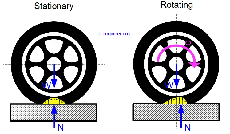
- In the image above: N [N] – normal reaction force, W [N] – weight force acting on the wheel and ω [rad/s] – angular speed of the wheel.
- When the tire is stationary, the distribution of the normal force N [N] in the contact patch is symmetric with respect with the vertical axis of the wheel. However,
- When the wheel is in motion (rotating), the normal force distribution is not anymore symmetric but concentrates in the front of the wheel, towards the direction of motion. This makes the resultant force N [N] to create a resistive rolling torque, which will try to slow down the wheel.
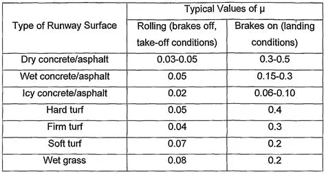
Rolling resistance coefficient
- The rolling resistance coefficient of a tire depends on tyre construction, materials, air pressure, vehicle speed, and road conditions. In general, for low vehicle speeds, the value of rolling resistance coefficient is constant.
- The rolling resistance coefficient slightly increases with the increase of the traveling speed of the vehicle. Under normal operating conditions, with the vehicle speed below 200 kph, the rolling resistance coefficient is between 0.01 – 0.02.
Tyre Pressure
-
Aircraft tires generally operate at high pressures, up to 200 psi (14 bar; 1,400 kPa) for airliners.
- Maintaining good pressure maintenance is right at the top of every list.
- No other tire has to deal with such high load and extreme speed as an airplane tire. So they need a bit more care than the tires on your car or motorcycle.
- role of the tire is holding the air at a pressure that is able to support the load of the airplane. (Nitrogen is normally used in commercial operations instead of air.)
- A Boeing 777 uses 14 tires, Airbus' A380 carries 22, and the enormous Antonov An-225 demands 32. The key to their remarkable durability is maximizing the air pressure.
- The high-flying rubber is typically inflated to 200 psi, roughly six times what you put in an automobile tire, and the tires on an F-16 fighter are pumped to 320 psi. “It's really pressurized air that's so strong,”.
Brake force
Airplanes rely on a braking system to safely land on runways. At cruising altitude, most commercial airplanes fly at a speed of roughly 500 to 600 mph. When landing, however, they must reduce their speed. A typical 747, for instance, has a landing speed of about 160 to 170 mph. And upon touching the runway, airplanes must quickly brake until they come to a complete stop. How do airplanes brake when landing exactly?
Wing Spoilers
Many airplanes use wing spoilers to assist with braking when landing. Not to be confused with ailerons, spoilers are extendable flaps on the ends of an airplane’s wings. Pilots can raise the spoilers to decelerate the airplane as it approaches the runway. And even while on the runway, pilots will typically leave the wing spoilers raised. Raised wing spoilers create drag, which essentially slows down the airplane so that it’s able to brake more quickly.
Disc Brakes
In addition to wing spoilers, airplanes use disc brakes. Airplane disc brakes are similar to the braking system in automobiles. They consist of a pair of calipers that, when engaged, squeeze pads against the rotors of an airplane’s landing gear.
Disc brakes are designed to remain static at all times. In other words, they don’t rotate with the wheels of an airplane’s landing gear. As the wheels turn, the disc brakes will remain static and stationary. They are a vital component of an airplane’s braking system because they are designed to apply pressure to the airplane’s wheels. Disc brakes will squeeze the wheels, thereby slowing down the speed at which they spin. In turn, this reduces the speed of the airplane so that it can come to a complete stop on the runway.
Reverse Thrust
Finally, many jet airplanes use reverse thrust to assist with braking during landings. Reverse thrust is a feature in jet engine airplanes that, as the name suggests, involves the reversal of the engines’ thrust. When flying, the thrust is projected out the rear of an airplane’s engines. When landing, however, pilots may use the reverse thrust feature. Reverse thrust changes the direction of the engines’ thrust. Rather than projecting out the rear, the thrust will be projected out the front. This reversal of thrust provides deceleration that allows airplanes to slow down more quickly when landing.
Part B:
6. A. With necessary assumptions, calculate the force and power required to push / pull an aircraft by a towing vehicle.
For towing / pushback basically 3 forces acting on the aircraft and tow vehicle,named as
- Rolling Resistance force
- Airdrag force
- Linear acceleration force.
To calculate above forces and power required by vehicle we have to consider some value of constants.
Assumption taken for the calculation
- We take Airbus A320 aircraft with takeoff weight of = 70,000 Kg-------------------------m1
- Push back tractor FOX.70D (Type towing/pushback) with weight of = 5000 Kg---------------------------m2
- Rolling resistance coefficient for vehicle and aircraft = µrr 0.03
- g =9.81m/s^2
- Air density ꝸ =1.225 Kg/m^3
- Drag coefficient of an aircraft Cd1 =0.012 (as aircraft is stipper at head portion )
- Drag coefficient of an Tow vehicle Cd2 =0.5 (flat in front )
- Initial and final velocity are 0 and 20 m/s
- Acceleration time = 10 sec.
- Total frontal area A = (300+200 )m2
ROLLING RESISTANCE (Frr) Frr = µrr*(m1+m2)g
Airdrag force = Fad=0.5*ꝸ*A*Cd*V^2
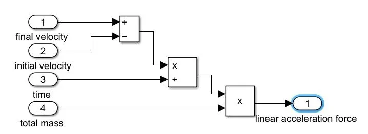
Linear acceleration force = Fla=( m1+m2)a
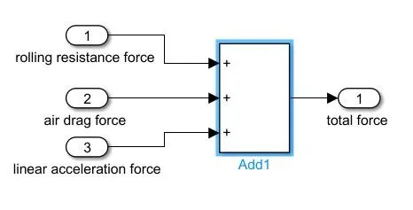
Total force required = Ft=Frr+Fad+Fla
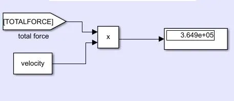
Total power required = Ft*V
Screenshot of excel sheet is attached below for further calculation.
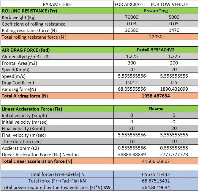
Hence total power required is 364 KW and force required is 65 KN.
B. Develop the model for the calculated force and power using Simulink.
- Firstly we have to defined some constant and variable in script file so that if we want to change the values we can change from the script file, file attached below.
https://drive.google.com/file/d/1UjFpvYEzV8wGzwwCdeCdpCoPC06W_flE/view?usp=sharing
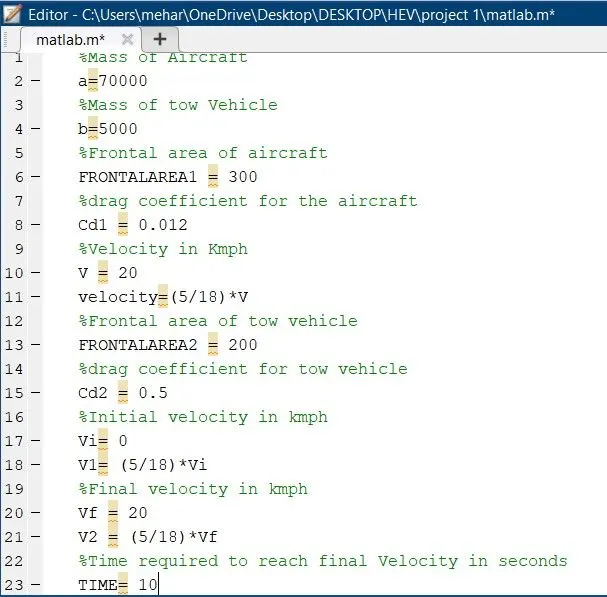
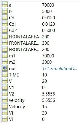
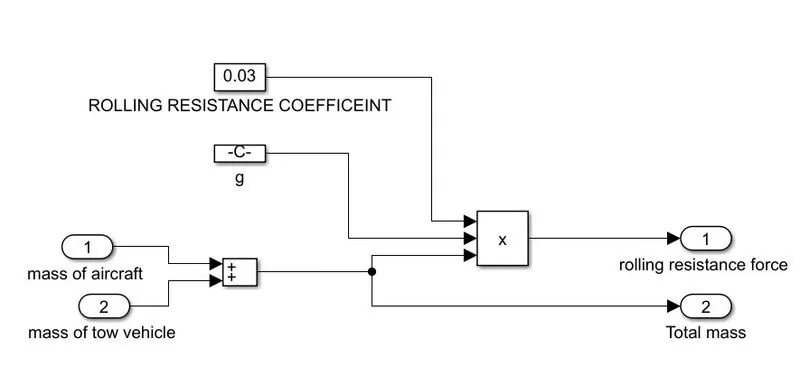
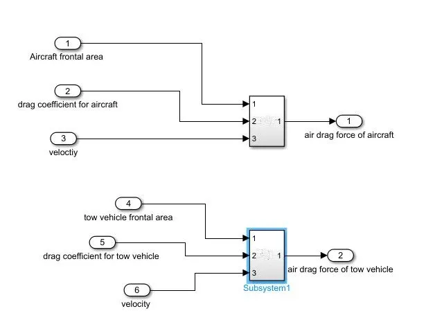
Now imulink model for the each force calculation are below and full model link is below
https://drive.google.com/file/d/1BtGTC7Z51dnf41CJtieeM1FY_pV9_0ZP/view?usp=sharing
ROLLING RESISTANCE FORCE
AIR DRAG FORCE
LINEAR ACCELERATION FORCE
TOTAL FORCE
TOTAL POWER
WHOLE MODEL
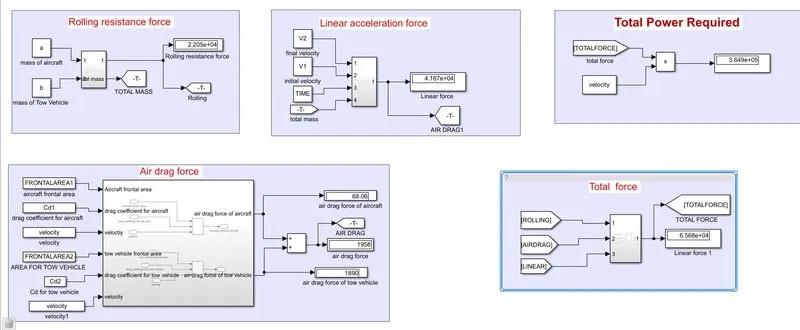
From simulink also total force and power required are 364861 W and 65675.15 N
--------------------------------------------------------------------------------------------------------------------------------------------------------------
7. A. Design an electric powertrain with type of motor, it’s power rating, and energy requirement to fulfill aircraft towing application in Simulink. Estimate the duty cycle range to control the aircraft speed from zero to highest. Make all required assumptions. Prepare a table of assumed parameters. Draw a block diagram of powertrain.
(Hint :DC7 Block)
As per above calculation we required power of 364861 W Force = 65675.15N
One of the DC electric motor we try simulate with rating of 405 KW and 480 V dc.
Torque need by tow vehicle = T = (FORCE * tyre radius)/(Gear ratio * Effeciency)
let the gear ratio is 30 radius of tyre be 0.15 and efficiency is 95%.
T = 345.65Nm
ω = P_out/T
ω= 364861/345.65 = 1055.57 rad/sec
ω = 10079 RPM
Now input power to motor = P_out / Efficency of motor --------------------------- let efficency = 90%
P_input = 364861/0.9 = 405KW
Input power required by the motor is given by battery , hence calculate battery power and rating .
At full load speed motor take full load current inour case full load speed of vehicle is 5.55 m/sec ,hence at that speed is current taken called as full load current
I = P_input / √3*V_rated* Power factor ----------------------let Pf = 0.90
I = 405000/√3*480*0.90 = 541.28
Battery voltage = P_input / I
V_battery = 405000/514.28 = 748.22
duty cycle = V_battery / Motor _ input voltage
Duty cycle = 480/748.22 =0.6412 =64.12%
64.12% of 748.22 battery voltage must be given to motor to run at 5.55 m/sec speed.
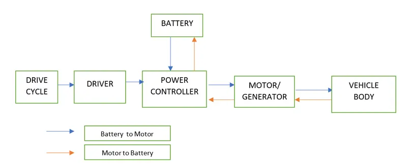
Block diagram of Powertrain
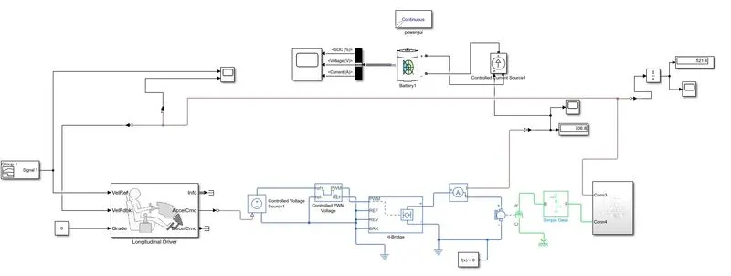
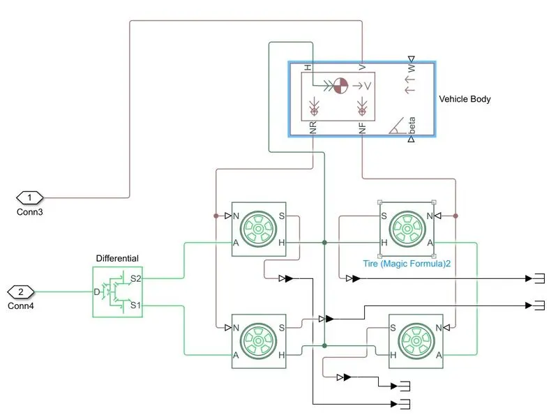
MODEL IN MATLAB
https://drive.google.com/file/d/1TyjBpx4BKW106IrC0IAUfSkivurwiI-V/view?usp=sharing
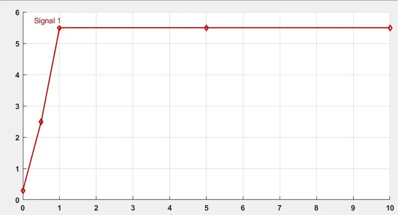
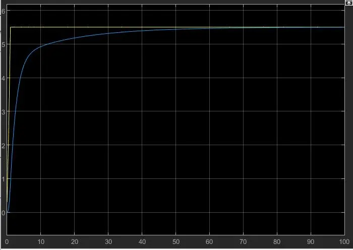
Input refrence speed given to vehicle 5.55 m/sec
Results
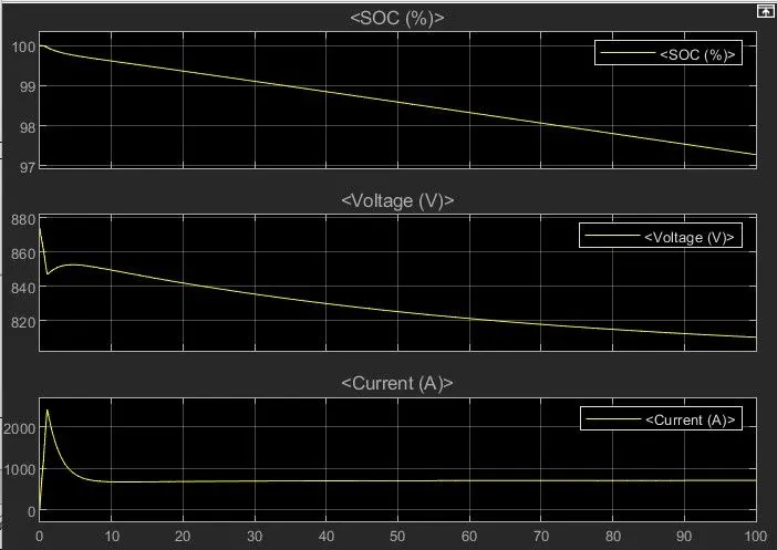
Model run for 100 sec
- Actural speed of vehicle and refrence speed of vehicle matched at 70 sec. Yellow -refrence speed and blue Actual speed.
- SOC drop is 70 sec is 100 to 98%
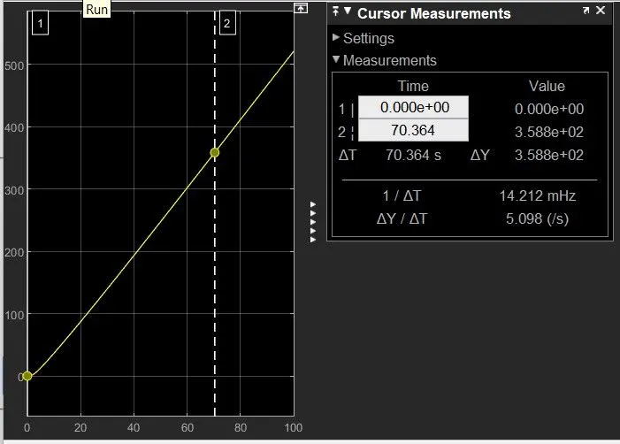
- Distance travelled in 70 sec is 358 m
Vehicle can run upto 153 KM in 45 minutes as per the simulation and battery discharge capacity of 541.28 Ah
means vehicel reach to 153 KM and battery is totally discharge (SOC = 0%)
B. Also, Design the parameters in excel sheet.
Assumption taken are same as before question
.
--------------------------------------------------------------------------------------------------------------------------------
Conclusion and learning
- Understanding of aircraft and there diffrent speeds and diffrerent operation and weights.
- Understanding to type of towing system vehicle use to towing .
- Diffrent types of forces applied on the tow and aircraft and their calculation.
- Simulation of matematical equation using simulink and scipt.
- Vehicle motor modelling using matlab and simulink.