Project-1: Powertrain for aircraft in runways
AIM:-
1. Search and list out the total weight of various types of aircrafts.
2. Is there any difference between ground speed and air speed?
3. Why is it not recommended to use aircraft engine power to move it on the ground at Airport?
4. How an aircraft is pushed to runway when its ready to take off?
5. Learn about take off power, tyre design, rolling resistance, tyre pressure, brake forces when landing.
6. With necessary assumptions, calculate the force and power required to push / pull an aircraft by a towing vehicle.
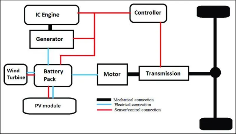
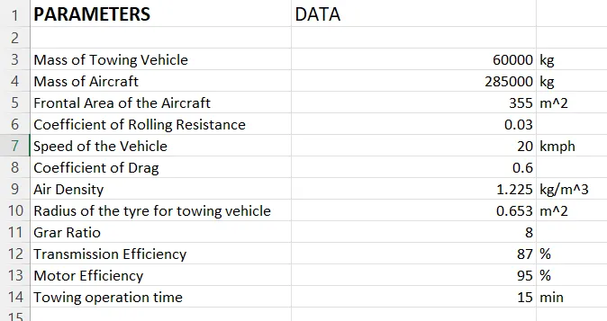
7. Design an electric powertrain with type of motor, it’s power rating, energy requirement to fulfill aircraft towing application. Estimate the duty cycle range to control the aircraft speed from zero to highest. Make all required assumptions. Prepare a table of assumed parameters. Draw a block diagram of powertrain.
DESCRIPTION:-
1. LIST OUT THE TOTAL WEIGHT OF VARIOUS TYPES OF AIRCRAFTS:
The aircraft gross weight (also known as the all-up weight and abbreviated AUW) is the total aircraft weight at any moment during the flight or ground operation. An aircraft's gross weight will decrease during a flight due to fuel and oil consumption. An aircraft's gross weight may also vary during a flight due to payload dropping or in flight refueling.
The weights are classified as following:
Maximum design taxi weight (MDTW):
The maximum design taxi weight (also known as the maximum design ramp weight (MDRW)) is the maximum weight certificated for aircraft manoeuvring on the ground (taxiing or towing) as limited by aircraft strength and airworthiness requirements.
Maximum design takeoff weight (MDTOW):
It is the maximum certificated design weight when the brakes are released for takeoff and is the greatest weight for which compliance with the relevant structural and engineering requirements has been demonstrated by the manufacturer.
Maximum design landing weight (MDLW):
The maximum certificated design weight at which the aircraft meets the appropriate landing certification requirements. It generally depends on the landing gear strength or the landing impact loads on certain parts of the wing structure. The maximum landing weight is typically designed for 10 feet per second (600 feet per minute) sink rate at touch down with no structural damage.
Maximum design zero fuel weight (MDZFW):
The maximum certificated design weight of the aircraft less all usable fuel and other specified usable agents (engine injection fluid, and other consumable propulsion agents). It is the maximum weight permitted before usable fuel and other specified usable fluids are loaded in specified sections of the airplane. The MDZFW is limited by strength and airworthiness requirements. At this weight, the subsequent addition of fuel will not result in the aircraft design strength being exceeded.
Manufacuturer's empty weight (MEW):
It is the weight of the aircraft "as built" and includes the weight of the structure, power plant, furnishings, installations, systems and other equipment that are considered an integral part of an aircraft. This excludes any baggage, passengers, or usable fuel.
Pay load:
It is the carrying capacity of an aircraft. It includes cargo, people, extra fuel. In the case of a commercial airliner, it may refer only to revenue-generating cargo or paying passengers.
Operating empty weight (OEW):
It is the basic weight of an aircraft including the crew, all fluids necessary for operation such as engine oil, engine coolant, water, unusable fuel and all operator items and equipment required for flight but excluding usable fuel and the payload.
The total weights of various types of aircraft are shown below;
| Type | MTOW [kg] | MLW [tonnes] | TOR [m] | LR [m] |
|---|---|---|---|---|
| Airbus A220-100 | 59,000 | 50.80 | 1463 | 1356 |
| Airbus A220-300 | 65,000 | 57.61 | 1890 | 1494 |
| Airbus A300-600 | 163,000 | 138 | 2324 | 1536 |
| Airbus A300-600R | 192,000 | 140 | 2385 | 1555 |
| Airbus A310-200 | 142,000 | 123 | 1860 | 1480 |
| Airbus A310-300 | 157,000 | 124 | 2290 | 1490 |
| Airbus A318 | 59,000 | 57.5 | 1375 | 1340 |
| Airbus A319 | 64,000 | 62.5 | 1850 | 1470 |
| Airbus A320-100 | 68,000 | 66 | 1955 | 1490 |
| Airbus A321-100 | 83,000 | 77.8 | 2200 | 1540 |
| Airbus A330-200 | 242,000 | 180 | 2220 | 1750 |
| Airbus A330-300 | 242,000 | 185 | 2500 | 1750 |
| Airbus A340-200 | 253,500 | 181 | 2990 | |
| Airbus A340-300 | 276,700 | 190 | 3000 | 1926 |
| Airbus A340-500 | 371,950 | 240 | 3050 | 2010 |
| Airbus A340-600 | 367,400 | 256 | 3100 | 2100 |
| Airbus A350-900 | 270,000 | 175 | 2670 | 1860 |
| Airbus A350-1000 | 308,000 | 233.5 | ||
| Airbus A380-800 | 575,000 | 394 | 3100 | 1930 |
| Airbus A400M | 141,000 | 122 | 980 | 770 |
Here MTOW is Maximum Take Off Weight
MLW is Maximum Landing Weight
TOR is Take Off Run
LR is Landing Run
2. DIFFERENCE BETWEEN GROUND SPEED & AIR SPEED:
When we talk about speeds of aircraft there are two types of speed in aircraft One is the ground speed and other is the air speed.
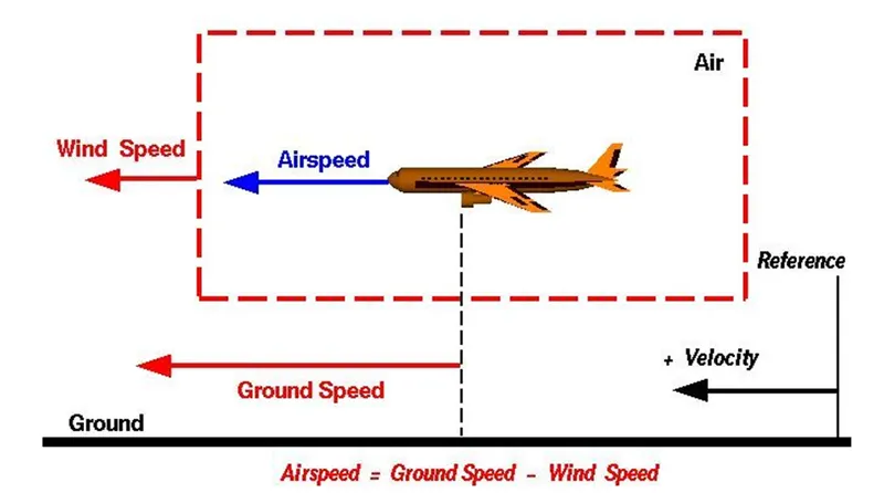
Ground speed:
It is the airplane's speed relative to earth's surface. One thing that should be noted here is that it’s its horizontal rather than vertical speed – an aircraft climbing completely vertically would have a ground speed of zero.
Air speed:
It is the airplane's speed relative to the air it is flying in. Air speed is what determines whether there is enough airflow around an aircraft to make it fly.
TYPES OF AIR SPEED:
(1). INDICATED AIR SPEED: It's an airspeed that is calculated directly off an aircraft’s pitot-static system. It’s the calculated off the aircraft’s dynamic pressure – the difference between its total pressure and static pressure. The dynamic pressure depends not only on the aircraft’s speed, but also on the density of the air it is flying in. As such, the higher the aircraft flies and the lower the air density as a result the bigger difference between the indicated and true air speed.
CALIBRATED AIR SPEED: It's ben adjusted for variety of errors. For an example, one of the things it’s adjusted for is the flap position. The reason for that is that at different flap positions, air flows differently around the pitot-static system and affects the indicated airspeed readings.
TRUE AIR SPEED: It's been mentioned numerous times the actual speed at which an aircraft is moving relative to the air it is traveling in. It’s calibrated airspeed adjusted for the the exact conditions (altitude, air temperature, etc.) that the aircraft is flying in. While ground speed is the airplane’s speed relative to the surface of the Earth, airspeed – at least true airspeed – is its speed relative to the air it is flying in.
- The aircraft operates on both ground as well as in the air so we need to obsreve how these speeds are related.
- The ground speed and air speed are usually depend on the wind speed.if the wind speed changes these speeds may change.
- if we consider there is no wind speed then the air sped is equal to the ground speed .
- If the wind is flowing in the same direction of the flight then (air speed < ground speed ) so air speed =ground speed -wind speed.
- If the wind is flowing in the opposite to direction of the flight then (air speed > ground speed ) so air speed =ground speed+wind speed.
3. WHY IS IT NOT RECOMMENDED TO USE AIRCRAFT ENGINE POWER TO MOVE IT ON THE GROUND AT AIRPORT:
Aircraft Engine power is not recommended to move on the ground at airport according to the following.
- Using ground tugs to move airplanes on the ground does save fuel in Airplanes.
- It also allows for precise parking as the tug driver can see the area around the airplane better than the pilot can from the flight deck
- Some aircraft can do a so-called ‘power back’, but in most cases, airplanes either don’t have this technical capability. Most airplanes can taxi backwards by using reverse thrust. This entails directing the thrust produced by the plane’s jet engines forward, rather than backwards. This method is often used in jet aircraft to brake as quickly as possible after touchdown. It’s also used when making an emergency stop. In some countries, pilots can still taxi their aircraft backwards to their heart’s content, but you’ll never see this at Schiphol. And for good reasons.
- Loud engines: Thrust reversal involves great forces, and produces an incredible amount of noise. To keep noise pollution to a minimum, we try to avoid roaring jet engines as much possible. An engine running at full thrust would also blow away any loose parts or people on the platform. Some might consider this a safety risk.
- Cleanliness is next to lower maintenance costs: Reversing engine thrust leads to an increase in CO2 production. In addition, thrust reversal can only be used above a certain speed, because otherwise all kinds of dirt will get sucked into the engines. This dirt then causes increased wear and tear of both the engine and the aircraft. All in all, plenty of reasons not to have airplanes taxiing in reverse.
- Back it up!: So how do we move our airplanes backwards? We use a pushback tractor. This special vehicle uses a tow bar, which is attached to the nose wheel of the aircraft. Modern pushback tractors are able to lift the aircraft’s nose wheel, making connecting and disconnecting the tow bar much less time-consuming. Once the tow bar is connected, the tractor is able to push the plane back. Beep, beep, beep – jumbo jet coming through!
- Hence Aircraft engine power is not recommended to move on the ground.
4. HOW AN AIRCRAFT IS PUSHED TO RUNWAY WHEN IT'S READY TO TAKE OFF:
The aircraft is now ready for baggage to be loaded for the next flight. A so-called pushback truck reverses the aircraft into taxiing position, pushing it with a towbar attached to the nose-wheel strut. Or, in the most modern versions, by actually lifting the wheel. That speeds up coupling and decoupling. In aviation, pushback is an airport procedure during which an aircraft is pushed backwards away from an airport gate by external power. Pushbacks are carried out by special, low-profile vehicles called pushback tractors or tugs. A pushback is therefore the preferred method to move the aircraft away from the gate.
READY TO TAKE-OFF:
- The pilot parks the aircraft in exactly the right place. Usually with the help of an automatic system, but occasionally guided by a marshaller waving two paddles or wands. Dozens of handling personnel are already standing by to perform a whole range of tasks simultaneously.
- As soon as the aircraft is stationary and the engines are switched off, the first priority is to disembark the passengers as quickly as possible. The apron handler places chocks in front of the wheels and connects the ground power. Meanwhile, the passenger bridge manoeuvres up to the door and a belt loader rolls up to the cargo hold. Luggage is unloaded and transferred to the terminal on baggage carts.
- Refuelling begins, usually from a hydrant at the stand. A hose is attached to this from a special vehicle called a dispenser, with the other side connected to the fuel tank in the wing. Read more about refuelling here.
- Now it is time to service the aircraft. The caterer loads new meals and takes away the food waste and used cutlery and crockery. Other activities include draining the lavatories, replacing the headrest covers, removing rubbish and distributing fresh blankets and in-flight magazine.
- A specialist team – or sometimes the crew themselves – cleans the cabin so that the new passengers board a pristine aircraft.
- Meanwhile, specialists from the airline conduct a technical check to make sure that the engines, wings, control surfaces, landing gear, instruments, doors and other equipment are in full working order.
- The aircraft is now ready for baggage to be loaded for the next flight. This is a quick process, on average taking only 10-15 minutes. A little later the passengers start boarding. As soon as they are all in their seats, the door is closed and the pilot informs air-traffic control that the flight is ready for departure.
- The apron handler removes the chocks. A so-called pushback truck reverses the aircraft into taxiing position, pushing it with a towbar attached to the nose-wheel strut. Or, in the most modern versions, by actually lifting the wheel. That speeds up coupling and decoupling.
- The aircraft taxis to the runway to depart at the agreed time.
- The pilot waits for permission to take off from air-traffic control. This is possible once the departure route is clear. As soon as the go-ahead is received, the plane takes to the air at full power.
5. LEARN ABOUT TAKE-OFF POWER, TYRE DESIGN, ROLLING RESISTANCE, TYRE PRESSURE, BRAKE FORCES WHEN LANDING:
TAKE-OFF POWER:
A power take-off (PTO) is any of several methods for taking power from a power source, such as a running engine, and transmitting it to an application such as an attached implement or separate machine. Most commonly, it is a splined drive shaft installed on a tractor or truck allowing implements with mating fittings to be powered directly by the engine. Semi-permanently mounted power take-offs can also be found on industrial and marine engines. These applications typically use a drive shaft and bolted joint to transmit power to a secondary implement or accessory. In the case of a marine application, such shafts may be used to power fire pumps. In aircraft applications, such an accessory drive may be used in conjunction with a constant speed drive. Jet aircraft have four types of PTO units: internal gearbox, external gearbox, radial drive shaft, and bleed air, which are used to power engine accessories. In some cases, aircraft power take-off systems also provide for putting power into the engine during engine start.
TYRE DESIGN:
An aircraft tire or tyre is designed to withstand extremely heavy loads for short durations. The number of tires required for aircraft increases with the weight of the aircraft, as the weight of the airplane needs to be distributed more evenly. Aircraft tire tread patterns are designed to facilitate stability in high crosswind conditions, to channel water away to prevent hydroplaning, and for braking effect. Aircraft tires also inclu (which are assembled on the inside of the wheels), designed to melt at a certain temperature. Tires often overheat if maximum braking is applied during an aborted takeoff or an emergrncy. The fuses provide a safer failure mode that prevents tire explosions by deflating in a controlled manner, thus minimizing damage to aircraft and objects in the surrounding environment.
ROLLING RESISTANCE:
Rolling resistance, sometimes called rolling friction or rolling drag, is the force resisting the motion when a body (such as a ball, tire or wheel) rolls on a surface. It is mainly caused by non-elastic effects; that is, not all the energy needed for deformation (or movement) of the wheel, roadbed, etc., is recovered when the pressure is removed. Two forms of this are hysterisis losses and permanent plastic deformation of the object or the surface (e.g. soil). Another cause of rolling resistance lies in the slippage between the wheel and the surface, which dissipates energy. Note that only the last of these effects involves friction therefore the name "rolling friction" is to an extent a misnomer. In analogy with sliding friction rolling resistance is often expressed as a coefficient times the normal force. This coefficient of rolling resistance is generally much smaller than the coefficient of sliding friction. Any coasting wheeled vehicle will gradually slow down due to rolling resistance including that of the bearings, but a train car with steel wheels running on steel rails will roll farther than a bus of the same mass with rubber tires running on tarmac. Factors that contribute to rolling resistance are the (amount of) deformation of the wheels, the deformation of the roadbed surface, and movement below the surface. Additional contributing factors include wheel diameter, load on wheel, surface adhesion, sliding, and relative micro-sliding between the surfaces of contact. The losses due to hysterisis also depend strongly on the material properties of the wheel or tire and the surface. For example, a rubber tire will have higher rolling resistance on a paved road than a steel railroad wheel on a steel rail. Also, sand on the ground will give more rolling resistance than concrete. Sole rolling resistance factor is not dependent on speed.
TYRE PRESSURE:
Each of the twelve Boeing-777-300ER main tires is inflated to 220 psi (15 bar; 1,500 kPa), weighs 120 kg (260 lb), has a diameter of 134 cm (53 in) and is changed every 300 cycles while the brakes are changed every 2000 cycles. Each tire is worth about $5,000. Aircraft tires generally operate at high pressures, up to 200 psi (14 bar; 1,400 KPa) for airliners, and even higher for business jets. The main landing gear on the concorde was typically inflated to 232 psi (16.0 bar), whilst its tail bumper gear tires were as high as 294 psi (20.3 bar). The high pressure and weight load on the Concorde tyres were a significant factor in the loss of AIr France Flight 4590 Tests of airliner aircraft tires have shown that they are able to sustain pressures of maximum 800 psi (55 bar; 5,500 kPa) before bursting. During the tests the tires have to be filled with water, to prevent the test room being blown apart by the energy that would be released by a gas when the tire bursts. Aircraft tires are usually inflated with nitrogen to minimize expansion and contraction from extreme changes in ambient temperature and pressure experienced during flight. Dry nitrogen expands at the same rate as other dry atmospheric gases (normal air is about 80% nitrogen), but common compressed air sources may contain moisture, which increases the expansion rate with temperature. The requirement that an inert gas, such as nitrogen, be used instead of air for inflation of tires on certain transport category airplanes was prompted by at least three cases in which the oxygen in air-filled tires had combined with volatile gases given off by a severely overheated tire and exploded upon reaching autoignition temperature. The use of an inert gas for tire inflation eliminates the possibility of tire explosion. The aircraft tire manufacturing industry is dominated by a four firm oligopoly that controls 85% of market share.
The four major manufacturers in aircraft tire manufacturing are
- Goodyear (United States)
- Michelin (France)
- Dunlop Aircraft tyres (United Kingdom)
- Bridgestone (Japan)
These firms control approximately 85% of the manufacturing market and account for most of the retreads. Dunlop is the smallest player among the major firms with revenue reported at £40m in a 2015 media report.
BRAKE FORCES WHEN LANDING:
Aircraft brakes stop a moving aircraft by converting its kinetic energy to heat energy by means of friction between rotating and stationary discs located in brake assemblies in the wheels. Brakes provide this critical stopping function during landings to enable airplanes to stop within the length of the runway. They also stop aircraft during rejected takeoff events, in which an attempted takeoff is canceled as the airplane is rolling down the runway before it lifts off from the ground due to engine failure, tire blowout, other system failure or direction from air traffic control. Aircraft brakes also prevent motion of the aircraft when it is parked, limit its speed during taxiing and can even help steer the aircraft on the ground by applying different levels of braking force to the left- and right-side brakes. Aircraft brakes work in conjunction with other brake mechanisms such as thrust reversers, air brakes and spoilers. Thrust reversers are surfaces that are deployed into the path of the jet blast from the engines to redirect propulsive thrust in a direction that opposes the motion of the aircraft. Air brakes and spoilers are flight control surfaces that create additional aerodynamic drag when deployed into the path of air flowing around the aircraft.
HOW AIRCRAFT BRAKES WORK:
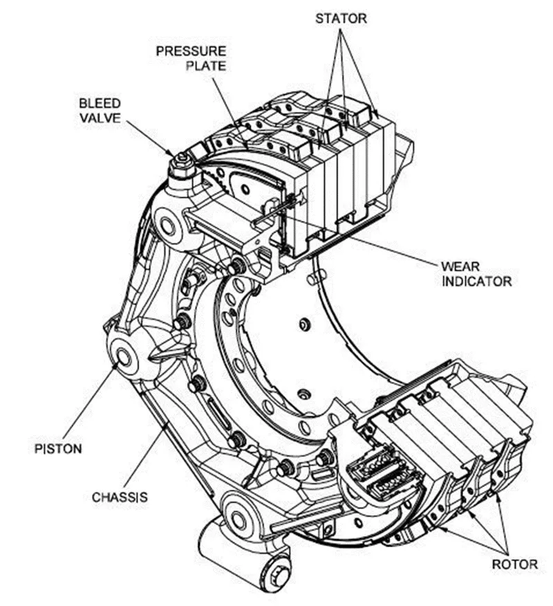
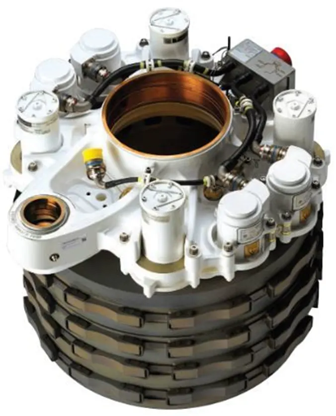
The most common type of brake used on aircraft is the disc brake. Disc brakes function by exploiting friction between rotating and stationary discs inside the brake. Upon receiving a command signal to brake — from the pilot depressing a foot pedal or from the autobrake system — actuators in the brake move a piston to squeeze the discs together, generating a frictional force that slows the rotation of the wheel. The friction between the discs generates heat as the aircraft’s kinetic energy is converted to heat energy. In this function, the brakes act as a heat sink, absorbing tremendous amounts of heat as the aircraft sheds kinetic energy. During RTO stops, the temperature of carbon disc brakes can exceed 1,800° C.Gulfstream G450 main landing gear brake assembly. Source: G450 Maintenance Manual via Code 7700
The discs are mounted on a carrier assembly consisting of a torque tube, which resists and transmits brake torque to the landing gear structure. Sandwiched together between the carrier assembly housing and a backing plate, the discs are arranged in an alternating pattern of rotors and stators. Notch and groove geometry around the circumference of each rotor fits into corresponding geometry in the wheel, keying the rotors to the wheel so that they rotate with it. The stators are keyed to the torque tube and are thus held stationary since the torque tube is connected to the axle and landing gear structure.
Cylindrical spaces within the carrier assembly hold actuator pistons. Braking occurs as piston force squeezes the discs together.
During each application of the brakes, disc material is worn away by frictional forces. A wear indicator in the form of a pin that protrudes out of the carrier assembly indicates the thickness of the stack of discs. Over hundreds of brake applications, material wears away and discs become thinner, requiring replacement following periodic maintenance intervals.
BRAKE DESIGN:
The primary design considerations for aircraft brakes include the number of discs, the diameter of the discs and the material of the discs. A major design point around which aircraft brakes are designed is the worst-case scenario of rejected takeoff (RTO) at the maximum rolling speed V1, known as the decision speed. Above V1, a takeoff could not be safely aborted without serious risk of the airplane failing to stop before the end of the runway. In this situation, the brakes need to absorb more energy than any other scenario. An A380’s brakes exhibit a red-hot glow during a rejected take off (RTO) test on the runway at ISTRES AFB in the south of France. Source: Airbus (Click image to enlarge)
To illustrate how much energy this is, consider an Airbus A380 — the world’s biggest passenger airplane — performing an RTO at V1. The maximum take-off weight of an A380 is 575,000 kg (1,267,658 lb) and its maximum V1 is around 170 knots (about 195 mph or 87 m/s). A rough estimate for the maximum energy that the A380’s 16 brakes need to dissipate during RTO can be obtained by calculating the kinetic energy of the aircraft (neglecting the effects of thrust reversers, air brakes, tailwinds, headwinds and runway slope).
Since kinetic energy (KE) is a function of mass (m) and velocity (v) according to the equation:
KE = ½mv2
The kinetic energy of the A380 during RTO is calculated as follows:
KE = 0.5 * 575,000 kg * (87.4556 m/s)2 = 2.2 x 10⁹ J = 2.2 GJ
2.2 GJ (gigajoules) is about the amount of energy an average cloud-to-ground lightning strike dissipates. It is also enough energy to power an 8 W LED light bulb (with light output equivalent to a 60 W light bulb) continuously for 8 years and 10 months
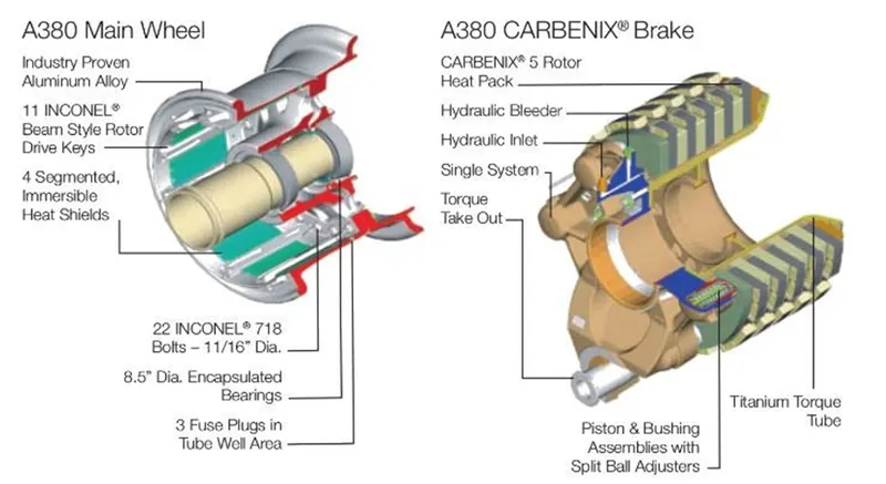
To generate the necessary frictional forces and to handle this much energy within the length of a runway, large commercial transport aircraft typically require multiple discs per brake assembly and brakes on most, if not all, of their wheels. For example, an A380 has 22 wheels distributed on five landing gear legs to support its massive weight: two nose wheels on a leg beneath the nose of the aircraft, eight wing wheels split between two legs that fold out from under the fuselage to support the left and right wings, and 12 body wheels split between two inboard landing gear legs under the fuselage. Sixteen of these wheels have brakes (four aft body wheels and the nose wheels are not braked). The A380 uses Honey well's Carbenix brakes. Each of the aircraft’s 16 brake assemblies has five rotors made of Carbenix 4000 carbon-carbon composite. The brake assemblies are located within wheels made of 2014-T6 aluminum alloy and attached to the axle and landing gear structure, which is comprised of 300 M high-strength alloy steel, titanium and aluminum components.
BRAKE MATERIALS:
The most common aircraft brake disc material until around 1963 was steel. The introduction of beryllium as a disc material provided improved thermal properties at the cost of material handling difficulties due to the toxic nature of beryllium oxide.
Carbon brakes became widely available for commercial airplanes starting in the 1980s. Carbon brakes — made of, for example, carbon fibers in a graphite matrix — are lighter, more durable, less thermally sensitive and have higher energy absorption and faster cooling rates compared to steel brakes. Compared to steel, carbon’s higher specific heat — the amount of heat that a unit mass of carbon absorbs to raise its temperature by one unit — enables reduced brake weight. Carbon’s higher thermal conductivity allows faster heat transfer and uniform heat distribution through the disc. Carbon also has lower thermal expansion, higher thermal shock resistance and a higher temperature limit than steel. The specific strength of carbon is relatively constant over a very wide range of temperatures, unlike steel and beryllium, which both exhibit steep declines in specific strength at high temperatures, dropping below carbon around 650° C (1,200° F).
Safran Landing Systems claims its Sepcarb III oxidation-resistant carbon brakes used on Boeing 787s are four times lighter, have three times higher endurance and have two to three times higher absorption capacity than steel brakes. UTC Aerospace Systems said its Duracarb carbon disk technology results in a weight-savings of 700 lbs (318 kg) per airplane for Boeing 737NGs compared to steel brakes. Other brake materials are available as well, such as Honeywell’s Cerametalix, a sintered combination of powdered metals and ceramics.
BRAKE ACTUATOR TYPE:
Brake actuators perform the critical task of squeezing discs together to generate the frictional forces that convert the aircraft’s kinetic energy of motion into heat to stop the aircraft. Most brake actuators on commercial aircraft are hydraulic, although electrically powered electromechanical actuators have entered service as well; the brakes on both the Airbus A220 (formerly known as the Bombardier C-series) and the 787 are electromechanically actuated. Hydraulic brakes are powered by the aircraft’s hydraulic system. A servo valve modulates the flow of hydraulic fluid to the hydraulic actuator to control the amount of braking force — the force with which the hydraulic cylinder presses the discs together. Electric brakes are powered by the aircraft’s electric system. Electricity is converted to mechanical power in the brake’s electromechanical actuators. In these actuators, an electric motor drives gears to turn a ball screw and nut to apply force to press the brake discs together. Redundancy is a necessary attribute built into aircraft braking systems due to the critical safety function that brakes provide. For example, the A380’s hydraulic brake system is powered by multiple separate 5,000 psi hydraulic systems. The set of brakes on the wing wheels and the set of brakes on the body wheels are attached to two separate hydraulic systems. The brake system is also supplied by a backup hydraulic system called the local electrohydraulic generation supply (LEHGS), which provides an alternate source of hydraulic power in the event of primary hydraulic system failure. The LEHGS generates hydraulic pressure with an electric motor-driven pump supplied by the aircraft’s electrical system. The design for the 787’s electric brakes also features redundancy. With four independent electromechanical actuators per wheel, operation of the 787 is permissible with 100% braking function available even if one of the electric brake actuators (EBAs) fails. The modular nature of the EBAs enables easy, in-situ maintenance during which a failed EBA can be quickly swapped out for a new one.
BRAKE COOLING:
The large amount of heat generated during aircraft braking is dissipated by means of passive or active cooling. Passive cooling occurs due to natural conduction of heat through the disc material and to surrounding components, radiation of heat off the brake and wheel assembly, and convection as air flows past and through the brake assembly. Active cooling is achieved by using fans that force air through the brakes. Fans are either built into the wheel or part of the external ground support equipment that is positioned against the wheel and removed once sufficient temperature drop has occurred.
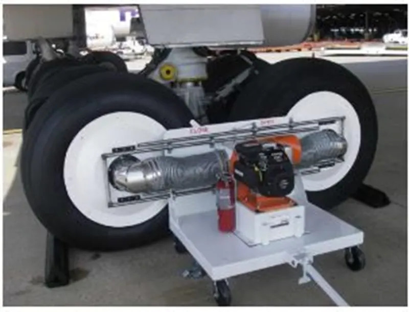
The GS100 aircraft brake cooler has a gas or diesel engine-powered fan that provides suction cooling for fast turnaround times.
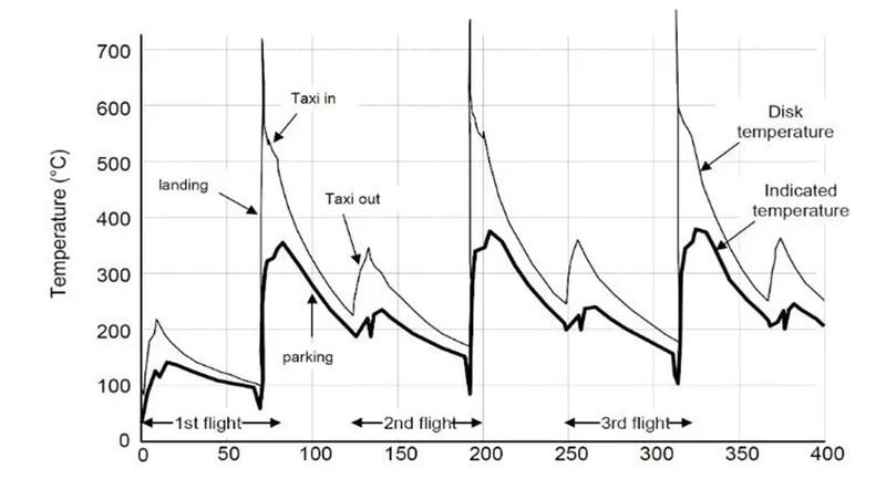
Example of brake temperature over time after three takeoff and landing cycles. Toward the end of a busy day full of short flights, it may be necessary to mandate a cooling period for hot brakes, during which the aircraft remains on the ground, to allow the brakes to cool so that they will not exceed the acceptable operating temperature range during RTO or landing.
AUTOBRAKES & SKID CONTROL:
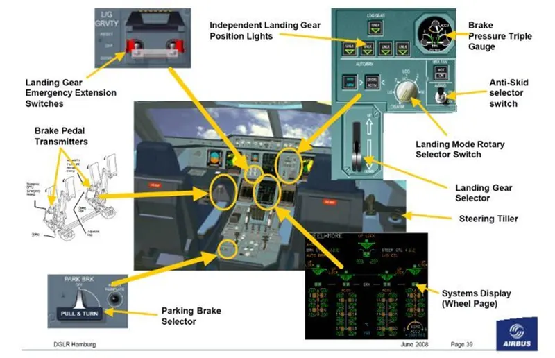
Modern commercial aircraft are equipped with an autobrake system that controls the deceleration of the aircraft by automatically optimizing the application of brake force independent of pilot operation of the brake pedals to minimize stopping distance, reduce pilot workload and smooth braking action.
Another common feature of aircraft brake systems is a skid control function. Similar to anti-lock brakes on an automobile, skid control systems prevent wheel lockup. They minimize stopping distance and prevent the negative effects of skidding on tires such as unnecessary tire wear and blowout. Skid control is accomplished by applying an optimal brake force that maximizes the coefficient of friction and remains just below the amount of force that would cause skidding. In one implementation, the proper force is arrived at by continuously sensing wheel speed and comparing it to a calculated aircraft velocity. The difference between the two values represents wheel slip and brake force is reduced if it rises above a specified value.
6.
A. WITH NECESSARY ASSUMPTIONS, CALCULATE THE FORCE & POWER REQUIRED TO PUSH/PULL AN AIRCRAFT BY A TOWING VEHICLE:
Let us assume;
Antonov An-225 Mirya
Mass of aircraft M1 = 285,000kg
Mass of Towing vehicle M2 = 60,000kg
Coeffiecient of rolling resistance for dry concrete road, µrr = 0.03
Frontal area of aircraft, A = 355m^2
Drag coefficient of an aircraft, Cd = 0.6
Drag coefficient of a towing vehicle, Cd = 0.15
Density of air =1.225kg/m^3
G = 9.81
Speed of an aircraft V =20 * (5/18) = 5.556 m/sec
ROLLING RESISTANCE FORCE:
For aircraft:
Frr = µrr * m * g
Frr = 0.03* 285000 * 9.81
= 83,875.5 N
For Towing Vehicle:
Frr = µrr * m * g
= 0.03*60,000 * 9.81
= 17,658N
We need to add the rolling resistance of both towing vehicle and aircraft.
Frr = Frr (aircraft) + Frr (vehicle)
Frr = 83,875.5 + 1765.8
Frr = 101,533 N
AERODYNAMIC DRAG FORCE:
Fad = (0.5) * ρ * V^2 *(Cd (aircraft) + Cd (vehicle))
= (0.5) * 1.225 * 335 * (5.556)^2 *(0.6 + 0.15)
= 4750.47 N
Total force of the towing vehicle,
F = Fad + Frr (vehicle) + Frr (aircraft)
F = 4750.47 + 17658 + 83875.5
= 106283.97 N
POWER REQUIRED:
P = F * V
= 106283.97 * 5.556
= 590.513 KW
The force and power of the towing vehicle carrying the aircraft are 106.283 KN and 590.513 KW respectively.
B. Develop the model for the calculated force and power using Simulink:
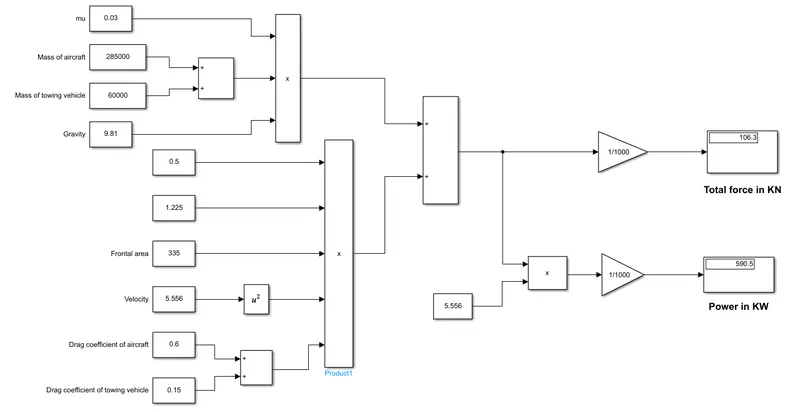
7.
A. DESIGN AN ELECTRIC POWERTRAIN WITH TYPE OF MOTOR IT'S POWER RATING & ENERGY REQUIREMENT TO FULLFILL AIRCRAFT TOWING APPLICATION, ESTIMATE THE DUTY CYCLE RANGE TO CONTROL THE AIRCRAFT SPEED FROM ZERO TO HIGHEST MAKE ALL REQUIRED ASSUMPTIONS, PREPARED A TABLE OF ASSUMED PARAMETERS, DRAW A BLOCK DIAGRAM OF POWERTRAIN:
Based on previous question,
Force required to push/pull the aircraft = 106.283 KN
Power required is = 590.513 KW
Let us assume the radius of the tyre as = 25 inches = 0.653m
Gear ratio = 8
Transmission efficiency (et) = 87%
Motor efficiency (em) = 95%
Then,
Torque required for the wheel (Tw) = Total force * Radius in meters
= 106.283 * 0.653
= 69.403KNm
Motor torque = wheel torque / (Gear ratio * et)
= 69.403 /(8 * 0.87)
= 9.9716 KNm
The required motor torque = 9.9716 / 0.95
= 10.49642
The total power required by the motor considering all efficiencies = 590.513 /(0.87 * 0.95)
=714.474KW
Let us assume the towing operation is done for 15 minutes (0.25 hrs)
Total energy consumed = 714.474 * 0.25
= 178.6185 Kwh
Duty cycle (d ) = (Required power)/ (Rated power)
= 714.474 / 950 = 0.752
= 75.2%
Thus the duty cycle range to control the aircraft speed from zero to highest is 0 to 75.2% .
POWER TRAIN:
Powertrain test rigs can now be built to be capable of using either the engine as the prime mover, or an electric motor simulating the engine. The evolution of such cells has been made possible by the comparatively recent development of permanent magnet motors (PMMs) and their associated controls in the automotive power ranges. These units are capable of engine simulation including that of most driveline dynamics and combustion pulses.The same motor technology has produced dynamometers having low inertia yet capable of absorbing high torque at low speeds, thus providing road wheel load simulation that, with customized controllers, includes tire-stiffness and wheel-slip simulation. An important logistical justification for such “all-electric” powertrain cells, besides not having to install and maintain all the cell services required by running an IC engine, is that the required engine may not be available at the time of the transmission test. One cost-effective arrangement that suffers from similar logistical problems of unit availability but which overcomes several rig design problems, where a complete (dummy or modified production) vehicle is mounted within either a two-wheel or “four-square” powertrain test tig.
It should be noted that, in spite of advances in motor and drive technology, flywheels still have a valuable part to play in transmission and powertrain testing and are often fitted to the free end of “wheel” dynamometers, a position that allows various flywheel masses to be fitted according to the demands of the test and UUT (see Chapter 11 for a discussion of flywheels). Powertrain rigs have to be designed to be able to take up different configurations on a large bedplate, as required by the UUT layout. A large tee-slotted test floor, made up of sections of cast-iron bedplates bolted together and mounted on “air springs” is the usual way to enable the various drive-motor or dynamometer units to be moved and aligned in typical powertrain configurations. However, a cheaper alternative for multiconfiguration transmission test rigs, which usually experience lower vibration levels than engine rigs, where steel slideways set into the concrete floor allow relative movement, albeit restricted, of the major dynamometer frames. To allow fast transition times the various test units should be pallet mounted in a system that presents a common height and alignment to the cell interface points.
POWERTRAIN BLOCK DIAGRAM:
B. Develop the model for the calculated force and power using Simulink:
CONCLUSION:-
1. Search and list out the total weight of various types of aircrafts is done.
2. Difference between ground speed and air speed is explained.
3. cleared that it not recommended to use aircraft engine power to move it on the ground at Airport.
4. An aircraft is pushed to runway when its ready to take off is illustrated.
5. Learn about take off power, tyre design, rolling resistance, tyre pressure, brake forces when landing are completed.
6. A. With necessary assumptions, calculate the force and power required to push / pull an aircraft by a towing vehicle.
B. Develop the model for the calculated force and power using Simulink are done.
7. A. Design an electric powertrain with type of motor, it’s power rating, and energy requirement to fulfill aircraft towing application in Simulink. Estimate the duty cycle range to control the aircraft speed from zero to highest. Make all required assumptions. Prepare a table of assumed parameters. Draw a block diagram of powertrain.
(Hint :DC7 Block)
B. Also, Design the parameters in excel sheet are done successively.