Project-1: Powertrain for aircraft in runways
*AIM:-
Part A:
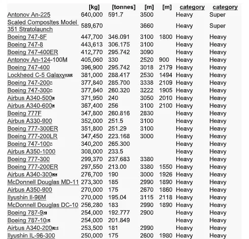
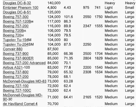
1. Search and list out the total weight of various types of aircraft.
2. Is there any difference between ground speed and airspeed?
3. Why is it not recommended to use aircraft engine power to move it on the ground at the Airport?
4. How an aircraft is pushed to the runway when it's ready to take off?
5. Learn about take-off power, tire design, rolling resistance, tire pressure, and brake forces when landing.
Part B:
6. A. With necessary assumptions, calculate the force and power required to push/pull an aircraft by a towing vehicle.
B. Develop the model for the calculated force and power using Simulink.
7. A. Design an electric powertrain with a type of motor, its power rating, and energy requirement to fulfill aircraft towing application in Simulink. Estimate the duty cycle range to control the aircraft speed from zero to highest. Make all required assumptions. Prepare a table of assumed parameters. Draw a block diagram of the powertrain.
(Hint: DC7 Block)
B. Also, Design the parameters in an excel sheet.
*SOLUTION:- <PART A>
Q1. Search and list out the total weight of various types of aircraft.
a)Aircraft Gross Weight:
- The aircraft gross weight (also known as the all-up weight and abbreviated AUW) is
the total aircraft weight at any moment during the flight or ground operation. - An aircraft's gross weight will decrease during a flight due to fuel and oil consumption.
An aircraft's gross weight may also vary during a flight due to payload dropping or in-flight refueling. At the moment of releasing its brakes, the gross weight of an aircraft is equal to its takeoff weight. During the flight, an aircraft's gross weight is referred to as the en-route weight or in-flight weight. - Aircraft gross weight limits are established during an aircraft's design and certification period and are laid down in the aircraft type certificate and manufacturer specification documents
- The absolute maximum weight capabilities of a given aircraft are referred to as the structural weight limits. The structural weight limits are based on the aircraft's maximum structural capability and define the envelope for the CG charts (both maximum weight and CG limits).
- An aircraft's structural weight capability is typically a function of when the aircraft was manufactured, and in some cases, old aircraft can have their structural weight capability increased by structural modifications.
b)Manufacturer's Empty Weight (MEW):
- Also called Manufacturer's Weight Empty (MWE) or Licensed Empty Weight It is the
weight of the aircraft "as-built and includes the structure, power plant, furnishings
installations, systems, and systems other equipment that are considered an integral part
of an aircraft.
c) Maximum Flight Weight (MFW):
- The maximum design taxi weight (also known as the maximum design ramp weight
(MRW)) is the maximum weight certificated for aircraft maneuvering on the ground
(taxing or towing) as limited by aircraft strength and airworthiness requirements
d) Maximum Takeoff Weight (MTOW)
- Is the maximum certificated design weight when the brakes are released for takeoff
and is the greatest weight for which compliance with the relevant structural and
engineering. the manufacturer has demonstrated requirements.
e) Maximum Landing Weight(MLW):
- The maximum certificated design weight at which the aircraft meets the appropriate
landing certification requirements. It generally depends on the landing gear strength of
the landing impact loads on certain parts of the wing structure. The MIW must not
exceed the MTOW. - The maximum landing weight is typically designed for 10 feet per second (600 feet per
minute) sink rate at touch down with no structural damage.
f) Maximum Zero-Fuel Weight(MZFW):
- The maximum certificated design weight of the aircraft less all usable fuel and other
specified usable agents (engine injection fluid, and other consumable propulsion
agents). It is the maximum weight permitted before usable fuel and other specified
usable fluids are loaded in specified sections of the airplaneThe MZFW is limited by strength and airworthiness requirements. At this weight, the
The subsequent addition of fuel will not result in the aircraft design strength being exceeded.
The weight difference between the MTOW and the MZFW may be utilized only for the
addition of fuel
g) Payload:
- It is the carrying capacity of an aircraft. It includes cargo, people, and extra fuel. In the case
of a commercial airliner, it may refer only to revenue-generating cargo or paying
passengers.
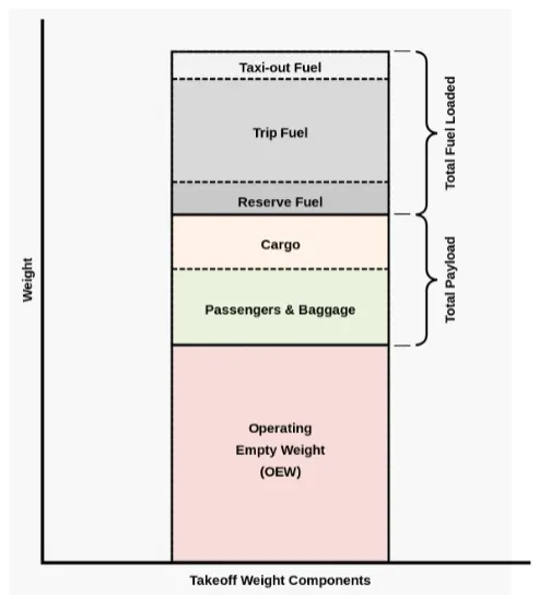
The following image depicts Takeoff Weight Components:
Q2. Is there any difference between ground speed and airspeed?
difference between ground speed and airspeed
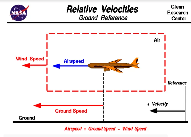
- One of the most confusing concepts for young scientists is the relative
velocity between objects. Aerodynamic forces are generated by an object
moving through a fluid (liquid or gas). - A fixed object in a static fluid does not generate aerodynamic forces. Hot air balloons "lift" because of buoyancy forces and some aircraft like the Harrier use thrust to "lift" the vehicle, but these are not examples of aerodynamic lift.
- To generate life, an object must move through the air, or air must move past the object. Aerodynamic lift depends on the square of the velocity between the object and the air. Now things get confusing because not only can the object be moved through the air, but the air itself can move.
- To properly define the relative velocity, it is necessary to pick a fixed reference point and measure velocities relative to the fixed point. The reference point is fixed to the ground in this slide, but it could just as easily be fixed to the aircraft itself.
- It is important to understand the relationships between wind speed to ground speed and airspeed.
Wind Speed:-
For a reference point picked on the ground, the air moves relative to the reference point at the wind speed. Notice that the wind speed is a vector quantity and has both a magnitude and a direction. Direction is important. A 20 mph wind from the west is different from a 20 mph wind from the east. The wind has components in all three primary directions (north-south, east-west, and up-down). In this figure, we are considering only velocities along the aircraft's flight path. A positive velocity is defined to be in the direction of the aircraft's motion. We are neglecting crosswinds, which occur perpendicular to the flight path but parallel to the ground, and updrafts and downdrafts, which occur perpendicular to the ground.
Ground Speed:-
For a reference point picked on the ground, the aircraft moves relative to the reference point at the ground speed. Ground speed is also a vector quantity so a comparison of the ground speed to the wind speed must be done according to rules for vector comparisons.
Airspeed:-
The important quantity in the generation of lift is the relative velocity between the object and the air, which is called airspeed. Airspeed cannot be directly measured from a ground position but must be computed from the ground speed and the wind speed. Airspeed is the vector difference between the ground speed and the wind speed.
Airspeed = Ground Speed - Wind Speed
Q3. Why is it not recommended to use aircraft engine power to move it on the ground at the Airport?
- Aircraft Engine Power is Not Recommended to be Used to Move It on The Ground at Airport Although many aircraft are capable of moving in backward using reverse thrust, as a result, the jet blast or prop wash might cause damage to the terminal building or equipment.
- Engine close to the ground may also blow sand and debris forward and then suck them into the engine, causing damage to the engine. Therefore there are pushback trucks in the airport.
- A pushback truck lifts the front wheel of the aircraft, their role in most airports is to move the aircraft away from the parking spot onto the taxiways, which is called towing
- For movement on the ground, the aircraft uses its own engine power, which is called taxing
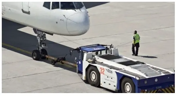
Although most aircraft are capable of moving themselves on the ground. it is not typically done due to the following reasons.
- Effectively a loss of control can happen, especially during high-power engine running.
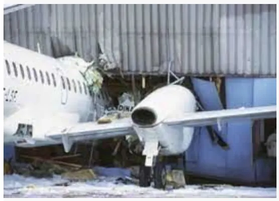
Damage can occur to the aircraft itself, other aircraft nearby or to airside structures. - There is a risk of injury to ground support personnel who may be in relative proximity to the aircraft.
- The jet blast from the engines can damage the terminal building and nearby equipment. It can even throw away people standing nearby.
- Engines can suck in sand and debris which can cause serious damage to the engine.
- It is easier for the truck driver to see the surroundings better than the pilot sitting in the cockpit with limited windows.
- The plane engines are very loud. When more than one plane will add up their sound then it will not be pleasant for passengers and s near the airport.
- It also saves fuel. Virgin Atlantic had proposed a new system in which pushback trucks will move the aircraft all the way to the runway to save fuel and reduce the impact on the environment.
- Modern planes are huge. It is difficult to navigate such gigantic structures through limited space. An A380 is eight stories high. The pilots won't be able to see anything directly in front of them or anything behind the wings
- In addition, response to potential but unexpected occurrences must be covered by appropriate training and, where a rapid response may be necessary, memory actions.
- Finally, engine ground running, especially if engine operation above Ground Idle is to take place, is best carried out with both flight deck pilot seats occupied and with clearly defined roles for the person in charge and their assistant. In particular, this allows checklists to be carried out using the challenge and response method.
Q4. How an aircraft is pushed to the runway when it's ready to take off?
>Phases of A Flight:-
- Taxiing refers to the movement of an aircraft on the ground, under its own power. The aircraft moves on wheels. An airplane uses taxiways to taxi from one place from an airport to another; for example, when moving from one terminal to the runway.
- The aircraft always move on the ground following the yellow lines, to avoid any collision with the surrounding buildings, vehicles or other aircraft. The taxiing motion has a speed limit. Before making a turn, the pilot reduces the speed further to prevent tire skids. Just like cars, there is a certain list of priorities during taxiing. The aircraft that are landing or taking off have higher priority. The other aircraft have to wait for these aircraft before they start or continue taxiing.
- The thrust to propel the aircraft forward comes from its propellers or jet engines. Steering is achieved by turning a nose wheel or tail wheel/rudder; the pilot controls the direction traveled with their feet. The use of engine thrust near terminals is restricted due to the possibility of jet blast damage. This is why the aircraft is pushed back from the buildings by a vehicle before it can start its own engines for taxiing.4.2
Take-Off:-
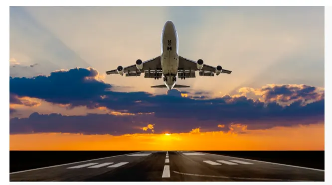
- Takeoff is the phase of flight in which an aircraft goes through a transition from moving along the ground (taxiing) to flying in the air, usually starting on a runway. usually, the engines are run at full power during takeoff. Following the tax motion, the aircraft stops at the starting line of the runway. Before takeoff, the engines, particularly piston engines, are routinely run up at high power to check for engine-related problems. This makes considerable noise. When the pilot releases the brakes, the aircraft starts accelerating rapidly until the necessary speed for take-off is achieved.
- The takeoff speed required varies with air density, aircraft weight, and aircraft configuration (flap and/or slat position, as applicable). Air density is affected by factors such as field elevation and air temperature.
- Operations with transport category aircraft employ the concept of the takeoff V- Speeds, V1 and V2. These speeds are determined not only by the above factors affecting takeoff performance but also by the length and slope of the runway. Below V1, in case of critical failures, the takeoff should be aborted; above V1 the pilot continues the takeoff and returns for landing. After the co-pilot calls V1, Then, V2 (the safe takeoff speed) is called. This speed must be maintained after an engine failure to meet per- performance targets for rate of climb and angle of climb.
- The speeds needed for takeoff are relative to the motion of the air (indicated airspeed). A headwind will reduce the ground speed needed for takeoff, as there is a greater flow of air over the wings. This is why the aircraft always take off against the wind. Sidewind is not preferred as it would disturb the stability of the aircraft. Typical takeoff air speeds for jetliners are in the 130–155 knot range (150–180 mph, 240–285 km/h). For a given aircraft, the takeoff speed is usually directly proportional to the aircraft weight; the heavier the weight, the greater the speed needed. Some aircraft have difficulty generating enough lift at the low speeds encountered during takeoff. These are therefore fitted with high-lift devices, often including slats and usually flaps, which increase the camber of the wing, making it more effective at low speed, thus creating more lift. These have to be deployed from the wing before performing any maneuver.
- At the beginning of the climb phase, the wheels are retracted into the aircraft, and the undercarriage doors are closed. This operation is audible by the passengers as a noise coming from below the floor.
Climb:-
- Following take-off, the aircraft has to climb to a certain altitude (typically 30,000 ft or 10 km) before it can cruise at this altitude safely and economically. A climb is carried out by increasing the lift of wings supporting the aircraft until their lifting force exceeds the weight of the aircraft. Once this occurs, the aircraft will climb to a higher altitude until the lifting force and weight are again in balance. The increase in lift may be accomplished by increasing the angle of attack of the wings, by increasing the thrust of the engines to increase speed (thereby increasing lift), by increasing the surface area or shape of the wing to produce greater lift, or by some combination of these techniques. In most cases, engine thrust and angle of attack are simultaneously increased to produce a climb.
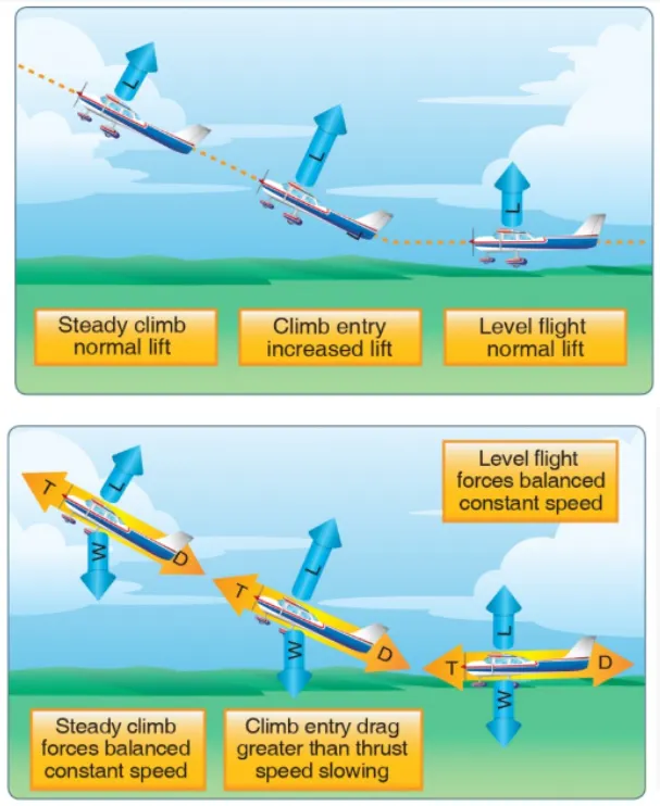
- Because lift diminishes with decreasing air density, a climb, once initiated, will end by itself when the diminishing lift with increasing altitude drops to a point that equals the weight of the aircraft. At that point, the aircraft will return to level flight at a constant altitude. During the climb phase, it is normal that the engine noise diminishes. This is because the engines are operated at a lower power level after the take-off. It is also possible to hear a whirring noise or a change in the tone of the noise during a climb. This is the sound of the flaps that are retracting. A wing with a retracted flap produces less noise.
Q5. Learn about take-off power, tire design, rolling resistance, tire pressure, and brake forces when landing.
a) TAKE-OFF POWER:
- Takeoff Power is the phase of flight in which an aerospace vehicle leaves the ground and becomes airborne On take-off, position the aircraft to a safe height away from terrain and obstacles (ie. a flight path of maximum height and minimum ground distance desired), the engine thrust is set to a high " take-off power setting and the aircraft attitude is pitched up to maintain a specific speed by fulfilling the task known as the taking-off power.
- Take-off performance can be predicted using a simple measure of the acceleration of the aircraft along the runway based on force equilibrium. The forces involved will be.
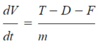
where,
T=Thrust of propulsion system pushing aircraft along the runway.
D=Aerodynamic Drag of vehicle resisting the aircraft motion
F=Rolling resistance friction due to the contact of wheels or skids on the ground. During take-off runs the imbalance in these forces will produce an acceleration along the runway.
DV/DT =Acceleration along with the runway
m =Mass of the vehicle.
whereas
Power =(T-D-F)*V
b) TYRE DESIGN:
- When it comes to safety tyres are one of the most important components of
aircraft. They help to absorb the shock of landing and provide cushioning. It also
provides the necessary traction for the braking and stopping of an aircraft. - An aircraft tire is designed to withstand extremely heavy loads while landing, taking off, taxing, and parking. The number of wheels required for aircraft increases with the weight of the aircraft, as the weight of the airplane, needs to be distributed more evenly.
- A Boeing 737NG & 737MAX uses 6 wheels, Boeing 787 uses 10 wheels, Boeing 777 uses 14 wheels and Airbus A380 uses 22 wheels. Aircraft tires work under extreme conditions, carrying up to 340 tons and accelerating at over 250 km/hour at takeoff, in addition to enduring varied environmental stress when in flight and taxiing.
Carcass plies are used to form the tire. They are sometimes called casing plies. An aircraft tire is constructed for the purpose it serves. - They support the weight of an aircraft while it is on the ground.
- It also provides the necessary traction for the braking and stopping of an
airplane. - Tyre also helps absorb the shock of landing and provides cushioning for the roughness of takeoff, roll-out, and taxi operations.
- Unlike an automobile or truck tire, it does not have to carry a load for a long period of continuous operation. However, an aircraft tire absorbs the high impact loads of landing, and also it’s operating at high speeds for a short time when
required.
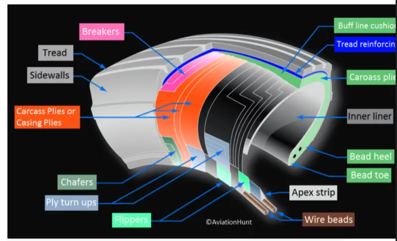
- Retreading = Retreading is restoring a worn tire by renewing the tread area or
renewing the tread area plus one or both sidewalls. Repairs are included in the
tire retreading process. - Load Rating = Load rating is the maximum permissible load at a specified
inflation pressure. - Ply Rating = Ply Rating is used to identify the maximum recommended load
rating and inflation pressure for a specified tire. It is an index of tire strength. - Speed Rating = The speed rating is the maximum takeoff speed to which the
tire has been tested. - Skid Depth = Skid depth is the distance between the tread surface and the
deepest groove as measured in the mold.
Aircraft tires may be Tube-type or Tubeless
c) ROLLING RESISTANCE:
Rolling resistance is the force resisting the motion when a body (such as a ball, tire, or
wheel) rolls on a surface.
Rolling resistance can be seen in the aircraft when the aircraft Takes off on the runway
with the help of from the runway and while landing its wheels.
The rolling resistance can be expressed
Fr =cW
where,
F= rolling resistance or rolling friction
c=rolling resistance coefficient - dimensionless (coefficient of rolling friction-CRF)
W=normal force or weight of the body
d) TYRE PRESSURE:
- Aircraft tires generally operate at high pressures, up to 200 psi(14 bar; 1.400
kPa) for airliners, and even higher for business jets. - The main landing gear on the Concorde was typically inflated to 232 psi (16.0
bar), whilst its tail bumper gear tires were as high as 294 psi (20.3 bar). - Tests of airliner aircraft tires have shown that they can sustain pressures of the
maximum of 800 psi (55 bar, 5.500 kPa) before bursting. During the tests, the
tires have to be filled with water, to prevent the test room from being blown apart
by the energy that would be released by a gas when the tire bursts Aircraft tires
are usually inflated with nitrogen to minimize - expansion and contraction from extreme changes in ambient temperature and
pressure experienced during flight. Dry nitrogen Laye expands at the same rate
as other dry atmospheric gases (normal air is about 80% nitrogen), but common
compressed air sources may contain moisture, rate with temperature. which
increases the expansion - The requirement that an inert gas, such as nitrogen, be used instead of air for
inflation of tires on certain transport category airplanes was prompted by at
least three cases in which the oxygen in air-filled tires combined with volatile
gases are given off by a severely overheated tire and exploded upon reaching auto-
ignition temperature The use of inert gas for tire inflation will eliminate the
possibility of a tire explosion
e) BRAKE FORCES WHEN LANDING:
- All commercial aircraft have automatic brake systems. Just like a car, these
systems also have an Anti-Lock braking system (ABS) that prevents the tires
from sliding down a wet runway. - The advantage of the automatic brake system is that the aircraft brakes
comfortably at a constant deceleration. Passengers experienced a constant force
that presses them into their seats. - The brake system automatically applies the wheel brakes just enough to create a
constant deceleration independent of the air resistance, spoilers, and reversers. It
is only in the last phase of brakes by pressing on both brake pedals. This
deactivates the automatic brake system. - Immediately after landing, the aircraft is still moving fast enough that
aerodynamic devices are much more efficient than the brakes. The brake units
are powered by the hydraulics system. - An electrical signal is sent from the flight deck to hydraulic actuators near the
main landing gear. Here, hydraulic fluid at 3.000 pounds per square inch is used
to force the brake unit against the wheel, thus slowing it down.
<PART B>
Q6. A. With necessary assumptions, calculate the force and power required to push/pull an aircraft by a towing vehicle.
B. Develop the model for the calculated force and power using Simulink.
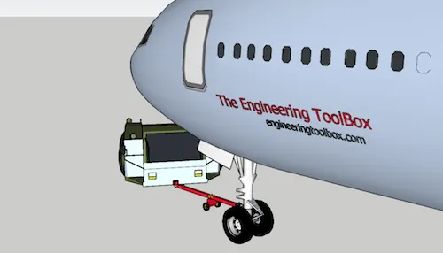
The force to move an airplane on an absolute flat runway with no wind at constant low speed is equal to the rolling resistance between the plane and the tarmac.
The rolling resistance for the airplane can be calculated as :
Fr = c mr ag (1)
where
Fr = rolling resistance (N, lbf)
c = rolling resistance coefficient
mr = rolling mass (kg, lbm)
ag = acceleration of gravity (9.81 m/s2)
The friction force for the puller can be calculated to
Ff = μ W
= μ mf ag (2)
where
Ff = frictional force (N, lb)
μ = friction coefficient
W = weight (N, lbf)
mf = friction mass (kg)
The drag force acting on the two will be :
The drag force D exerted on a body traveling through fluid is given by
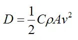
C is the drag coefficient, which can vary along with the speed of the body. But typical values range from 0.4 to 1.0 for different fluids (such as air and water)
ρ is the density of the fluid through which the body is moving
v is the speed of the body relative to the fluid
Now the tractive force or the pulling force required by the tow will be
Pulling force = Drag force + friction force + Rolling resistance force
Now let us consider aircraft with the following specifications :
Now as we have seen that various kinds of planes have different weights, the amount of pulling force also will be different. Therefore we will consider a range of weights:
Range of weight = 200 kgs - 250000 kgs '
The towing speed considered is 5 m/s
Area range: 50 - 100 m^2
Coefficient of rolling resistance : 0.02
Coefficient of friction: 0.01
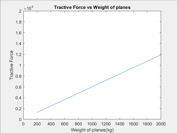
Now we use a script from Matlab which will help us calculate the pulling force required :
clc
clear all

%Inputs
c=0.002%Rolling resistance coefficient
m=linspace(200,25000,2000) % Weight
g=9.81 %acceleration of gravity
u=0.6%friction coefficient
A=linspace(50,100,2000)%area of planes
v=2 % velocity
Cd=0.8 %Drag Coefficient
%Calculations

F1=c*m*g %Rolling resistance force
F2=u*g*m%Friction force
F3=0.5*A*1.2*Cd*(v)^2
Ft=F1+F2+F3

plot(m,Ft)
title('Tractive Force vs Weight of planes')
xlabel('Weight of planes(kg)')
ylabel('Tractive Force')
axis([0 2000 0 20000]) 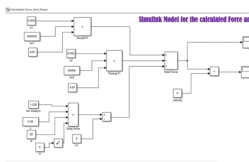
Results:-
Q7.A. Design an electric powertrain with the type of motor, its power rating, and energy requirement to fulfill aircraft towing applications in Simulink. Estimate the duty cycle range to control the aircraft speed from zero to highest. Make all required assumptions. Prepare a table of assumed parameters. Draw a block diagram of the powertrain.
(Hint: DC7 Block)
B. Also, Design the parameters in an excel sheet.
Consider the powertrain with the following specifications :
Vehicle Drive: 2.0 HP, 36 VDC Traction Motor mated with High-Efficiency Helical Gear Dana Axle Assembly
Batteries: Six 6 VDC, 190 AMP-HR Batteries (6 hr rate), wired in series.
Vehicle Speed, Loaded: 3.6 mph / 5.8 kph
Lift Cradle Capacity: 1,500 lbs / 680 kg
Now, this can be represented in Simulink in the following manner :
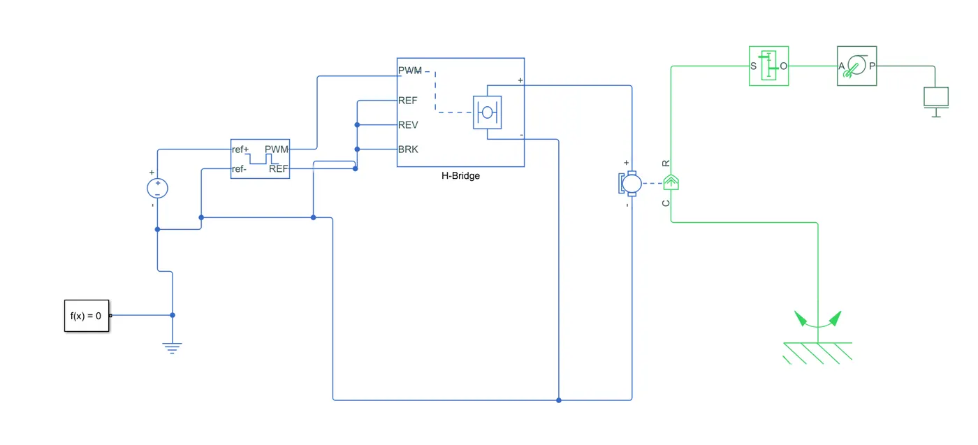
The following components were used :
1. PWM Module :
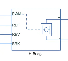
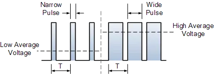
Pulse width modulation speed control works by driving the motor with a series of “ON-OFF” pulses and varying the duty cycle, the fraction of time that the output voltage is “ON” compared to when it is “OFF”, of the pulses while keeping the frequency constant.The power applied to the motor can be controlled by varying the width of these applied pulses and thereby varying the average DC voltage applied to the motor terminals. By changing or modulating the timing of these pulses the speed of the motor can be controlled, ie, the longer the pulse is “ON”, the faster the motor will rotate, and likewise, the shorter the pulse is “ON” the slower the motor will rotate. In other words, the wider the pulse width, the more average voltage applied to the motor terminals, the stronger the magnetic flux inside the armature windings, and the faster the motor will rotate and this is shown below.
2. Motor :
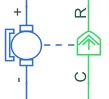
The motor is a dc motor having two terminals, the rotor R and the case c which are fixed to a stationary frame. The motor produces the amount of torque required and gives it to the gearbox.
3. Gearbox, wheel axle, and Mass
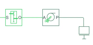
The gearbox input shaft is connected to the output of the motor and is given a gear ratio of 10 to produce the required torque. The gearbox gives the required torque to the wheel axle which has the mass attached to it.
Results:-
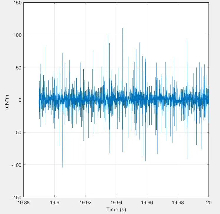
Torque produced at wheel axle for a mass of = 1000 kgs :